*e-mail: darriba@bol.com.br
1. Introduction
Aluminum oxide, commonly referred to as alumina (Al2O3), has interesting properties, such as high thermal insulation, electrical resistivity, hardness, good resistance to wear and corrosion, besides having physical stability at high temperatures1,2.Owing to that, alumina can be used as abrasives, protective ilms for optical, electronic and
micro-electronic segments, passivation layers, hardener coatings for tools and other applications3.
Alumina is a polymorphic material being the crystalline
alpha (α) phase the responsible for these notorious
properties3. But the precipitation of the α-Al 2O3 is complex because its growth is compromised by a large
number of existing metastable phases2,4. In addition to this fact, the alpha phase is obtained only under high working temperatures. The chemical vapor deposition (CVD)
technique commonly, employed to prepare alumina ilms,
requires substrate temperatures of around 1000 °C1-4. This fact turns the application of such a coating impractical for materials sensitive to high temperatures3.
Several techniques using different experimental apparatus have been reported in the literature to obtain
amorphous and crystalline alumina ilms. Carta et al.3 deposited amorphous alumina coatings on AISI 304 stainless steel substrates by the metal organic chemical vapor deposition (MOCVD) in a hot wall reactor at 380 °C with oxygen in the atmosphere.
Innovative Low Temperature Plasma Approach for Deposition of Alumina Films
Felipe Augusto Darriba Battaglina*, Ricardo Shindi Hosokawaa, Nilson Cristino da Cruza, Luciano Caselib, Elidiane Cipriano Rangela, Tiago Fiorini da Silvac, Manfredo Harri Tabacniksd
aLaboratório de Plasmas Tecnológicos, Universidade Estadual Paulista – UNESP,
Câmpus Experimental de Sorocaba, Avenida Três de Março, 211, Alto da Boa Vista, CEP 18087-180, Sorocaba, SP, Brasil
bDepartamento de Ciências Exatas e da Terra, Universidade Federal de São Paulo – UNIFESP,
Rua Artur Riedel Eldorado, CEP 09972-970, Diadema, SP, Brasil
cDepartamento de Física Nuclear, Universidade de São Paulo – USP, Rua do Matão, Travessa R,
187, Cidade Universitária, CEP 05508-900, São Paulo, SP, Brasil
dDepartamento de Física Aplicada, Universidade de São Paulo – USP, Rua do Matão, Travessa R,
187, Cidade Universitária, CEP 05508-900, São Paulo, SP, Brasil
Received: April 13, 2014; Revised: November 17, 2014
Alumina ilms were deposited from a new plasma method using aluminum acetylacetonate (AAA)
powder as precursor. The AAA was sputtered in argon and oxygen plasma mixtures. It was investigated the effect of the oxygen proportion (O2%) on the properties of the coatings. Deposition rate was derived
from the layer height measured by proilometry. The elemental composition and molecular structure of the ilms were determined by Rutherford backscattering and infrared spectroscopies, respectively. Grazing incidence X-ray diffraction was used to investigate the microstructure of the ilms while
hardness was determined by nanoindentation technique. Inspections on the surface morphology and on
the ilm composition were conducted associating scanning electron microscopy and energy dispersive
spectroscopy. Incorporation of oxygen affects the plasma kinetics and consequently the properties of the coatings. As moderated concentrations of oxygen (< 25%) are added, the structure is predominantly organic containing stoichiometric amorphous alumina. On the other hand, as high O2% (> 25%) are incorporated, the structure become rich in metallic aluminum with carbon rising at low proportions. The deposited layer is not homogeneous in thickness once the chemical composition of the precursor
is changed by the action of the reactive oxygen plasma. Oxygen ablation on the ilm surface also
contributes to the lack of homogeneity of the structure, especially as high oxygen proportions are imposed. Hardness data (0.5-2.0 GPa) corroborated the idea of an amorphous structure. Based on the results presented here it was possible to identify the oxygen concentration in the plasma atmosphere which mostly removed organics while preserving the stoichiometric alumina precipitation, subject of great relevance as one considers the reduction in the energy necessary for the creation of fully oxide coatings.
Another example is showed by Caussat et al.5, in which SiO2 powder has been coated by alumina through the
luidized bed chemical vapor deposition process associated
with the metal organic precursor, aluminum acetylacetonate (Al(acac)3). The temperature range was 400-620 °C.
Maruyama et al.6 deposited amorphous alumina ilms by low-temperature atmospheric-pressure CVD using aluminum acetylacetonate. The precursor, thermally decomposed in air at 150 °C, was carried to the reaction
chamber by a nitrogen gas low, where it was exposed to
temperatures ranging from 250 to 600 °C. Authors justify the choice of the AAA by its low toxicity and simplicity of handling.
The same compound was used in the work of Muhsin et al.7 providing amorphous and crystalline alumina ilms. As in the Maruyama’s6 work, the precursor was, decomposed at temperatures of around 247 °C and carried to a wall heated-CVD reactor operating at atmospheric pressure. Films deposited at 500 °C were transparent, amorphous and mechanically/chemically stable. Annealing at temperatures higher than 800 °C led to alumina crystallization.
In the work of Jeon et al.8 amorphous alumina thin ilms were deposited by the plasma-enhanced atomic-layer
deposition (PEALD) method. Two different precursors, dimethylaluminum isopropoxide and trimethylaluminum, were employed associated with the oxygen as the reactant
gas in the plasma. Using the iltered vacuum arc method,
with a highly pure aluminum cathode and oxygen gas, Yamada-Takamura et al.1 obtained crystalline and amorphous phases of alumina with a temperature of the substrate between 500-780 °C.
Cibert et al.9 deposited ilms by PLD (Pulsed Laser Deposition) and PECVD at room temperature and 800 °C. Trimethylaluminium (TMA), used as the precursor, was admitted to the reaction chamber by a flow of argon
passing through it. Amorphous ilms were found at room
temperature, while crystalline ones were obtained at 800 °C. Kyrylov and co-workers10 deposited alumina ilms on molybdenum super alloy and stainless steel substrates from gaseous mixtures (AlCl3, O2, H2 and Ar). For that, they used a bipolar mid frequency PECVD system, varying the substrate temperature from 500 to 620 °C. The results revealed
that ilm structure and properties were inluenced by the
plasma parameters and gas composition. Furthermore, the
temperature for the precipitation of the α-alumina (~ 500 °C)
was lower than the reported by the CVD method.
Lin and co-workers11 deposited ilms on glass and silicon substrates by radio frequency PECVD. The depositing plasmas were generated from AlCl3, CO2 and H2 mixtures while heating the sample holder to 300-500 °C. Transparent, colorless and amorphous Al2O3 ilms resulted from all the experiments even with heating of the samples.
Among the processes mentioned above, the PECVD technique has received particular attention due to the possibility of obtaining alumina layers at low temperatures. Owing to this fact, numerous studies have been performed employing this technique. In a recent publication, Nielsen and co-workers12 proposed a new plasma approach, based in the PECVD apparatus, for depositing amorphous alumina
ilms from aluminum acetylacetonate, a non-toxic, cheap and
easy to handle powder normally used for chemical vapor
depositions. The novelty of Nielsen’s work was to place the
AAA powder directly inside a capacitively coupled plasma reactor and to sputter it in argon radiofrequency plasmas. Besides demonstrating the feasibility of the method to
prepare amorphous alumina ilms, it was revealed that ilm
properties, as the proportion of organic contamination, are strongly dependent on the power of the radiofrequency signal employed in the driven electrode.
In this context, the present work aims to study the effect of the plasma chemical composition on the properties of the
ilms produced by this new methodology. Speciically, it is
intended to address the effect of oxygen incorporation into
argon plasmas, on the properties of the ilms. Oxygen has
a high reactivity towards carbon and may act as an organic scavenger, contributing to the reduction in the energy
necessary for formation of fully oxide ilms. Furthermore,
oxygen radicals in the plasma may reduce the activation energy and increase the reaction with the aluminum precursors, thereby favoring the growth of crystalline phases at lower temperatures5.
2. Experimental
2.1. Deposition procedure
Figure 1 schematically shows the apparatus used for
ilm deposition, following the methodology proposed by
Nielsen et al.12. Basically, it is composed by a stainless steel reactor containing two parallel plate electrodes (119 mm in diameter, 50 mm apart) inside the reactor. A Tokyo Hy-Power RF-300 radiofrequency power supply (13.56 MHz, 300 W) is connected to one of the electrodes while the remaining one and the chamber walls are earthed.
The system is evacuated by a mechanical rotative pump (Edwards E2M18), being the pressure monitored by a capacitive membrane sensor (Edwards Barocel 600). Gases are introduced in the reactor via stainless steel pipes passing through needles valves (Edwards LV-10K).
Glass, stainless steel and aluminum plates were used
as substrates for ilm deposition. The substrates were irst
cleaned in ultrasonic baths, according to the procedures described in a previous work13. The cleaned samples were attached to the uppermost electrode of the plasma system using adhesive tape and submitted to a plasma ablation procedure to further clean and activate the substrate surfaces. The parameters employed for that are described in Table 1. To generate the depositing plasmas, 0.8 grams of aluminum acetylacetonate (C15H21AlO6) from Aldrich Chemistry with 99% purity, was spread directly on the lowermost electrode and not decomposed at high temperature
Table 1. Parameters of the sputtering process.
Sputtering Process
Chemical composition Argon and hydrogen
Argon / hydrogen proportion 50% / 50%
Gas pressure 1.33 Pa
Time 10 minutes
for vapor generation, as demonstrated in previous works that used the PECVD technique with acetylacetonate. The system was pumped down to achieve the base pressure of 4.3 Pa. Argon and oxygen mixtures were admitted in the reactor raising the system pressure to 11 Pa; thereby the gas pressure (oxygen and argon) used was 6.7 Pa. The plasma was ignited by the application of radiofrequency power (13.56 MHz, 150 W) to the lowermost electrode containing the powder of AAA, while grounding the sample holder and the chamber walls. Eight different depositions were conducted changing, from run to run, the acetylacetonate powder and varying the chemical composition of the plasma atmosphere. For that, the proportion of oxygen was increased in the gas mixture from 0 to 100% while that of argon was proportionally decreased to keep the total gas
pressure constant in 11 Pa. The respective gas low added
for each deposition cycle is shown in Table 2. Deposition time was 5400 s.
The temperature was measured by a digital thermometer directly on the lowermost electrode, shortly after opening the reactor. The temperature did not exceed 60 °C, value close to that found by Nielsen et al.12.
2.2. Film characterization
Thickness of the films was measured in samples prepared on glass plates with a step delineated during
ilm deposition. For that, part of the glass surface was
masked with a plasma resistant Kapton tape (3M 5413) and exposed to the deposition procedure. After deposition, the Kapton mask was removed revealing the step between
the exposed and protected regions. The height of the step
was determined with the aid of a Dektak 150 proilemeter
at six different positions of the sample. The analysis was
performed considering scans of 200 μm and under a tip
load of 3.0 mg. Deposition rate was evaluated as the ratio
between ilm thickness and deposition time.
The average roughness of the samples prepared on
glass plates was derived from topographic proiles acquired by proilometry, in the same device used for thickness
measurements. For the calculations, three scans of 200 µm were taken from different points of each sample using a tip load of 3.0 mg.
The elemental composition of the films prepared on stainless steel or on aluminum plates were inspected simultaneously by Rutherford Backscattering Spectroscopy (RBS) and Forward Recoil Spectroscopy (FRS) at LAMFI-USP using 2.4 MeV He++ particles. The beam incidence angle was 80°, the detector for RBS measurements was placed at 170° scattering angle and for FRS 20° scattering
angle (and with a 6-μm thick aluminum ilter) referred to
the beam direction. From the simulation of the spectra with the SIMNRA code14, the concentration of the sample species was obtained.
Infrared reflectance absorbance spectroscopy was employed to investigate the molecular structure of the films in a Jasco FTIR-410 spectrometer. The spectra, collected from samples deposited on polished stainless steel substrates, correspond to the average between 128 scans with 4 cm–1 of resolution. In addition, Polarization-Modulation Infrared Relection Absorption Spectroscopy, PM-IRRAS, was employed to inspect the ilm surface. A KSV PMI 550
Instrument spectrometer was used for that.
To evaluate if there was precipitation of crystalline
phases of alumina in the ilms, grazing incidence X-ray
diffraction (GXRD) experiments were conducted in samples deposited on amorphous glass plates. The measurements
were performed in a Panalytical X’Pert Powder XRD-6000
diffractometer using a Cu K-alpha (40 kV, 30 mA) radiation source and varying the scanning detector angle from 20 to 90° at a rate of 10.5°/min. Incidence angle was 1°.
Inspections on the surface morphology and elemental composition of the samples prepared on 304 stainless steel plates were conducted associating scanning electron microscopy (SEM) and energy dispersive spectroscopy (EDS). The analyses were accomplished in a Jeol JSM-6010LA (Analytical Scanning Electron Microscope)
equipment using secondary electrons detector with beam energy of 2.5 kV (spot size 3 nm and penetration depth around 150 nm).
Hardness was determined from samples prepared on glass plates in a nanoindenter Hysitron Triboindenter. A pyramidal Berkovich tip was employed using a multiple step partial unload trapezoidal function. In this function,
the maximum load was varied from 80 to 1000 μN in ten
steps while the application, removal and dwell times were
ixed in 1s. The results, obtained using the Oliver and Pharr
method15, correspond to the average of 15 indentations conducted for each one of the ten applied force.
3. Results and Discussion
Figure 2 shows the deposition rate of the films as a function of the oxygen concentration in the plasma.
Deposition rate irstly increases (7.8 to 25.2 nm/min) as O2% is elevated from 0 to 20%, suddenly falls (0.59 nm/min) as 25% of oxygen is present, keeping roughly constant with increasing O2% beyond 25%. Interestingly, a behavior very similar to that was reported in the work of Lin et al.11 with changing the radiofrequency power employed to the sample holder to excite plasmas from AlCl3, CO2 and H2 mixtures. A maximum in deposition rate was reached as power was increased to 200 W followed by a sudden drop with further increasing power. These results were ascribed to changes
Table 2. Proportions of oxygen-argon and gas low employed in each one of the 8 deposition cycles.
Deposition Cycles
Oxygen proportion [%] Oxygen low [sccm] Argon proportion [%] Argon low [sccm]
0 0 100 9.21
10 1.83 90 8.20
20 2.16 80 7.53
25 2.25 75 7.00
40 2.83 60 6.01
60 3.51 40 4.52
80 4.65 20 2.80
100 5.70 0 0
in the plasma kinetics and in the self bias voltage with increasing the excitation power.
In the work of Nielsen et al.12, deposition rates from 0.1 to 81.3 nm/min were obtained with changing the plasma excitation power from 50 to 300 W but with no oxygen incorporation. Considering oxygen addition, it clearly accelerates deposition rate as moderate proportions (20%) are used. Once sputtered to the plasma phase, AAA molecules or fragments can be further activated prior deposition, enhancing the overall plasma reactivity. Since
oxygen has a high afinity towards the organic part of the
AAA, activation is more prone to occur as oxygen is present in the plasma. Furthermore, the interaction of atomic oxygen
with the deposited ilm may also generate active sites for ilm deposition. That is, oxygen favors the activation of the plasma and of the ilm species, both accelerating the
deposition process.
However, as oxygen proportion exceeds 20%, there is alteration in the deposition-removal balance due to changes promoted in three phenomena. Firstly, the ejection of AAA constituents to the plasma by sputtering is substantially reduced since O atoms are lighter than Ar ones. Secondly, the removal of newly deposited species from the substrate surface by the etching process rises16. Finally, there is a higher probability of oxidizing the aluminum part of the molecule in the plasma phase, then reducing the availability
of reactive aluminum precursors for ilm formation since
oxide groups are very stable.
Aside to these effects, the chemical composition of the precursor may also be changed as oxygen is incorporated.
The afinity of oxygen towards carbon and hydrogen tends
to preferentially remove organics from the AAA powder, turning more inorganic the remaining precursor in the
reactor. During the irst stages of the deposition process the
etched organic functionals can be activated in the plasma
phase and incorporated in the ilm structure, however, in the inal stages they are no longer abundant in the depositing
atmosphere, resulting in a gradient layer in which the inorganic fraction grows from the substrate to the surface.
The elemental composition of the ilms, derived from the
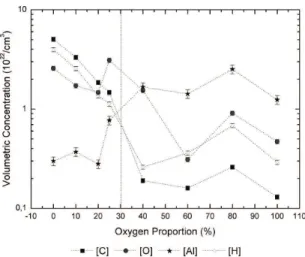
RBS results, is presented as a function of O2% in Figure 3.
For the ilms deposited with 0 to 20% of oxygen in the
plasma, C, O and H are the prominent species in the structure with aluminum rising in smaller concentrations (ten times
lower). While the proportions of the irst three elements are
observed to linearly fall with increasing O2% up to 20%, the proportion of Al keeps roughly constant. Interestingly, as 25% of oxygen is incorporated in the plasma phase, the concentrations of Al and O in the structure grow. For higher oxygen proportions (> 25%) the concentration of carbon
atoms is reduced (~ 2 orders of magnitude) while that of Al
increases, becoming the prominent species in the structure. In this case, oxygen and hydrogen concentrations assume intermediary position between that of Al and C. The dotted vertical line in the graph represents the transition from a structure with excess of carbon to another with excess of Al, showing that oxygen incorporation in the plasma phase indeed acts as a carbon scavenger but when in excess
(> 25%) tends to result in metallic aluminum ilms. The Al/O
ratio intensity, depicted in Figure 4, clearly demonstrates such a transition.
Furthermore, as the availability of reactive oxygen in the plasma grows the etching of organics from the newly deposited surface also increases, further contributing to originate a gradient structure with abundance of Al in uppermost interface. Indeed the roughly constant carbon
concentration in the ilms even with the increment in O2% may be a result of the stronger C incorporation during the
irst stages of the deposition process.
The infrared spectra of the ilms deposited on polished
304 stainless steel, using 0, 10 and 20% of oxygen in the plasma, are shown in Figure 5. The absorptions detected in
these spectra were collected and identiied in Table 3. All the other samples resulted in featureless spectra due to the low amount of deposited material associated to the high fraction of metallic aluminum in the structure.
Bands related to stretching (2876, 2933 and 2966 cm–1)12 and bending (1464, 1403 and 1293 cm–1)12 vibrations of C-H groups were detected altogether with those ascribed to
stretching (~3447 cm–1) modes of O-H groups6. Carbonyls (C=O) are also identiied by the absorptions around 170412 and 159617 cm–1. As connected to aluminum groups, such bands emerge at 153112 cm–1.
Figure 3. Concentrations of C, H, O and Al of the ilms as a
function of O2%.
In the low wavenumber region of the spectra (500 – 1200 cm–1)6, the presence of aluminum is detected by the absorptions at 1026 (ν Al=O)12, 935 (LO Al
2O3) 1, 862 (ν Al-O)12 and 670 (TO Al
2O3)
1 cm–1, overlapped to a large and intense contribution ranging from 500 to 1200 cm–1, characteristic of amorphous alumina1. Even as oxygen is incorporated at low concentrations (10%), the intensity of
the bands related to the amorphous alumina (≤ 1000 cm–1)1 becomes more prominent than that observed for the organic ones (1250-2000 cm–1)12.
The polarization modulation infrared spectra of the samples, acquired in the 800 to 1200 cm–1 region, are presented in Figure 6. They represent the difference between the signal taken from the bare glass substrate (background)
Figure 5. Relectance-absorbance infrared spectra of the ilms deposited with different oxygen concentrations in the plasma.
Table 3. Wavenumber of the absorption bands present in the infrared
spectra of the ilms and their respective assignments.
Wavenumber [cm–1] Assignment
3447 ν O-H
2966 ν C-H
2933 ν C-H
2876 ν C-H
1704 C=C
1596 ν C=O
1531 ν C=O connected to aluminum
1464 δ C-H
1403 δ C-H
1293 δ C-H
1026 ν Al=O
935 LO Al2O3
862 ν Al-O
670 TO Al2O3
Figure 6. PM-IRRAS spectra for the ilms deposited using different
and the film containing glass. The wavenumbers and respective assignments of all contributions were collected in Table 4. The most prominent contribution in the spectra, emerging at 1011 cm–1, is characteristic of the stretching vibration of Al=O groups12. Further indication of Al incorporation is provided by the large contribution in the 800 to 950 cm–1 region, which may originate from amorphous alumina12 and/or from Al-O17 (860 cm–1) stretching vibrations. Maruyama et al.6 also veriied the rise of a broad band lying from 500 to 1000 cm–1 in the infrared spectra of the ilms which was attributed to vibrations of
Al2O3 groups. These two stronger absorptions are similar for all the samples, showing no dependency on the oxygen proportion. Aside to these, lower intensity contributions, created from deformations of O-H groups and O-H connected to the Al2O3 structure18, are evidenced around 1173 and 1084 cm–1, respectively. Incorporation of hydroxyl groups in alpha alumina was also reported by Giner et al.19 in the same region and using the same analysis.
Therefore, regardless the oxygen proportion which was employed, the spectra presented in Figure 6 relect surfaces with the same molecular structure unless for slight changes. This result is ascribed to the depletion of organics from the
ilm surfaces caused by the plasma ablation as well as to the inorganic nature of the AAA in the inal stages of the
deposition.
The creation of an amorphous structure is further
conirmed as one considers the GXRD results of the ilms
(not shown). This result is coherent with the previous work of Nielsen et al.12 as well as with other reports in the literature20, in which amorphous alumina ilms were derived from low temperature plasma depositions. According to estimations20, the sample holder does not reach 100 °C under the conditions employed here.
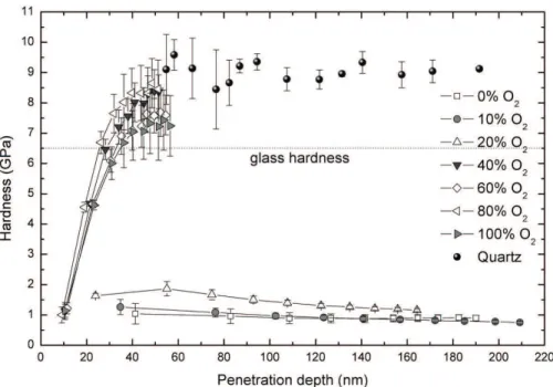
Figure 7 shows the hardness of the ilms as a function of the penetration depth of the diamond tip. Hardness values
for the standard quartz plate (9.0 GPa), also presented in this graph, were used to calibrate the indenter tip area.
For the thinnest ilms (O2% > 20%) no conclusive results are obtained since the tip senses the underlying glass substrate (6-7 GPa). On the other hand, for the thickest layers (O2% < 20%), almost straight lines, lying between
Table 4. Wavenumber of the absorption bands and assignment
present in the PM-IRRAS spectra.
Wavenumber [cm–1]
Assignment
1173 Deformations of O-H groups
1084 O-H connected to the Al2O3
1011 ν Al=O
950 to 800 Amorphous alumina and/or ν Al-O (860 cm–1)
Figure 7. Hardness of the ilms as a function of the penetration depth of the diamond tip.
Figure 8. Roughness of the ilms deposited on glass substrates as
0.5 and 2.0 GPa, are obtained for the substrate interference free region (< 100 nm). For 0 and 10% of oxygen, values commonly found in plasma deposited organic materials
(~1.0 GPa) are measured in good agreement with the results
reported by Nielsen and co-workers12. Hardness increases about twice (~ 2.0 GPa) as 20% of oxygen was employed for ilm deposition, corroborating the previous interpretation
of an amorphous oxide-richer structure for this sample. Figure 8 shows the average roughness, Ra, of the ilms as a function of O2%. Despite some oscillations, a rise trend is observed with increasing the oxygen concentration in the plasma phase. Ra values between 5 and 11 nm were found as O2% was changed from 0 to 25%. These results are slightly higher than the reported by Cibert and co-workers9 for the
roughness of alumina ilms deposited at room temperature
on silicon substrates using the PECVD technique. The rising trend in Ra is ascribed to two primary effects. First of all, the interaction of reactive oxygen groups with the surface generates defects on the growing layer elevating the number
of active sites for ilm growth. Furthermore, the abundance
of oxygen during the depositions also promotes the removal of species from the surface through the etching process16. Both phenomena contribute to defect generation justifying the roughness increment.
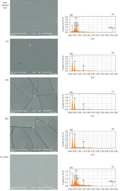
Figure 9 shows the scanning electron micrographs and EDS spectra of the samples deposited on polished stainless steel substrates. The same results for the bare substrate, presented in Figure 9(a), reveal a lat surface containing
Figure 9. Secondary electron micrographs (beam energy of 2.5 kV, spot size 3 nm and penetration depth around 150 nm) and EDS spectra
scratches and the common elements found in this alloy (C, Cr, Ni, Si, Mn, P and S)21. After submission to the depositing plasma (O2% = 0), the surface morphology slightly changes with the disappearance of the scratches present in the metallic surface. The presence of a uniform
coating is readily conirmed by detection of C, Al and O
and by disappearance of the alloying elements in the EDS spectrum of this sample. As oxygen is incorporated in the plasma (up to 20%), there is rise of cracks over the entire surface. The same phenomenon was observed in the work of Nielsen et al.12 as ilm thickness reached around 2 µm, being associated to the fragile nature of the oxide ilms
and to the elevation in the internal stress promoted by the thickness enhancement. Carbon, oxygen and aluminum are still detected on the cracked surface. The C/Al intensity ratio, evaluated from the EDS peaks and presented in Figure 10,
clearly shows a fall trend then conirming the effect of O on
the organic components12. Consistently with the increment in the ilm thickness, the intensity of the peaks ascribed to
alloying elements vanishes in the EDS spectra. Finally, with increasing oxygen concentration beyond 20%, a surface with no cracks and relatively uniform develops, indicating that plasma process affects in a lower extent the surface
morphology. The ilm elements are barely detected by the
EDS analysis due the penetration depth of the probing electron beam. Further indication of changes is obtained from the morphology of these samples which present a higher uniformity than the observed in the bare substrate.
In general, the analysis derived from SEM and EDS data are in good agreement with those established from RBS and infrared results.
4. Conclusions
Films were deposited from the reactive sputtering of aluminum acetylacetonate in argon and oxygen plasma mixtures. The proportion of oxygen incorporated was observed to affect the plasma kinetics. Deposition rate
is inluenced by the oxygen addition since it reduces the
sputtering of AAA, increases the ablation of the deposited material and decreases the content of reactive aluminum available in the plasma for deposition. Chemical changes are also expected in the precursor and on the growing layer due to the action of the plasma atmosphere affecting the overall morphology and roughness of the surfaces.
It was clearly identiied a transition from a regime
in which oxygen addition scavenges the organic part of the structure to another one that results in predominantly
metallic ilms. Amorphous alumina was detected in the bulk and on the surface of the ilms being their proportions
dependent on O2%. Films are amorphous since the deposition proceeded at temperatures lower than 100 °C.
The thickest ilms containing high proportions of alumina
cracked; lower deposition times are proposed to reduce the layer thickness while preserving higher oxides proportions. Hardness results are consistent with the amorphous nature
of ilms and also with the presence of organics in deeper
regions of the coatings.
Considering all these results, the optimum proportion of oxygen in the plasma was considered to be 25% since it promoted the lowest C content while preserving the oxide nature of the coating. For this condition, Al/O ratio was the closest to that of alumina and no cracks were detected in
the ilm structure, a positive point as one considers practical
applications. The study conducted here was of substantial importance since it will enable a reduction in the energy necessary to formation of fully oxide coatings using this new methodology. For that, it is proposed to associate resistive heating or ion bombardment, recognized carbon scavenger methods, to the reactive sputtering of the AAA.
Acknowledgements
The authors would like to acknowledge FAPESP (Fundação de Amparo à Pesquisa do Estado de São Paulo)
for inancial support (2009/07604-3 and 2012/14708-2).
Figure 10. C/Al intensity ratio obtained from the EDS peaks for
samples where the ilm was detected.
References
1. Yamada-Takamura Y, Koch F, Maier H and Bolt H.
Characterization of α-phase aluminum oxide films deposited
by filtered vacuum arc. Surface and Coatings Technology. 2001; 142-144:260-264. http://dx.doi.org/10.1016/S0257-8972(01)01206-3.
2. Wallin E. Alumina thin ilm growth: experiments and modeling. [Dissertation]. Linköping: Linköping University; 2007.
3. Carta G, Natali M, Rigato V, Rossetto G, Salmaso G and Zanella P. Chemical, morphological and nano-mechanical
characterizations of Al2O3 thin films deposited by metal organic chemical vapour deposition on AISI 304 stainless steel.
Electrochimica Acta. 2005; 50(23):4615-4620. http://dx.doi. org/10.1016/j.electacta.2004.10.097.
4. Sarakinos K, Music D, Nahif F, Jiang K, Braun A, Zilkens C, et al. Ionized physical vapor deposited Al2O3 films: does
subplantation favor formation of α-Al2O3? Physica Status
Solidi (RRL): Rapid Research Letters. 2010; 4(7):154-156. http://dx.doi.org/10.1002/pssr.201004133.
vapor deposition from aluminum acetylacetonate. Chemical Engineering Journal. 2012; 211-212:68-76. http://dx.doi. org/10.1016/j.cej.2012.09.048.
6. Maruyama T and Arai S. Aluminum oxide thin films prepared by chemical vapor deposition from aluminum acetylacetonate.
Applied Physics Letters. 1992; 60(3):322-323. http://dx.doi. org/10.1063/1.106699.
7. Muhsin AE. Chemical vapor deposition of aluminum
oxide (Al2O3) and beta iron disilicide (β-FeSi2) thin ilms. [Dissertation]. Essen: Universität Duisburg; 2007.
8. Jeon S, Jeon H Koo J and Kim S,. Characteristics of Al2O3 thin films deposited using dimethylaluminum isopropoxide and trimethylaluminum precursors by the plasma-enhanced-atomic-layer deposition method. Journal of the Korean Physical Society. 2006; 48(1):131-136.
9. Cibert C, Hidalgo H, Champeaux C, Tristant P, Tixier C, Desmaison J, et al. Properties of aluminum oxide thin films deposited by pulsed laser deposition and plasma enhanced chemical vapor deposition. Thin Solid Films. 2008; 516(6):1290-1296. http://dx.doi.org/10.1016/j.tsf.2007.05.064. 10. Kyrylov O, Cremer R and Neuschutz D. Deposition of alumina
hard coatings by bipolar pulsed PECVD. Surface and Coatings Technology. 2003; 163-164:203-207. http://dx.doi.org/10.1016/ S0257-8972(02)00482-6.
11. Lin CH, Wang HL and Hon MH. Preparation and characterization of aluminum oxide films by plasma enhanced chemical vapor deposition. Surface and Coatings Technology. 1997; 90(1-2):102-106. http://dx.doi.org/10.1016/S0257-8972(96)03100-3.
12. Nielsen GF. Filmes orgânicos contendo óxido de alumínio depositados a plasma. [Dissertation]. Sorocaba: Universidade Estadual Paulista; 2011.
13. Mancini SD, Nogueira AR, Rangel EC and Cruz NC. Solid-state hydrolysis of post consumer polyethylene terephthalate after plasma treatment. Journal of Applied Polymer Science. 2013; 127(3):1989-1996. http://dx.doi.org/10.1002/app.37591.
14. Mayer M. SIMNRA: a Simulation Program for the Analysis of NRA, RBS and ERDA. In: Proceedings of the 15th International Conference on the Application of Accelerators in Research and Industry; 1999; Denton. American Institute of Physics Conference Proceedings; 1999. p. 541.. http://dx.doi. org/10.1063/1.59188.
15. Li H and Vlassak JJ. Determining the elastic modulus and hardness of an ultra-thin film on a substrate using nanoindentation. Journal of Materials Research. 2009; 24(03):1114-1126. http://dx.doi.org/10.1557/jmr.2009.0144.
16. Sant’Ana PL. Tratamento a plasma de polímeros comerciais transparentes. [Dissertation]. Sorocaba: Universidade Estadual Paulista; 2010.
17. Nielsen GF, Silva LHF, Cruz NC and Rangel EC. Preparation of films from aluminum acetylacetonate by plasma sputtering.
Surface and Interface Analysis. 2013; 45(7):1113-1118. http:// dx.doi.org/10.1002/sia.5236.
18. Thissen P, Wielant J, Köyer M, Toews S and Grundmeier G. Formation and stability of organophosphonic acid monolayers on ZnAl alloy coatings. Surface and Coatings Technology. 2010; 204(21-22):3578-3584. http://dx.doi.org/10.1016/j. surfcoat.2010.04.027.
19. Giner I, Maxisch M, Kunze C and Grundmeier G. Combined in situ PM-IRRAS/QCM studies of water adsorption on plasma modified aluminum oxide/aluminum substrates.
Applied Surface Science. 2013; 283:145-153. http://dx.doi. org/10.1016/j.apsusc.2013.06.059.
20. Chryssou CE and Pitt CW. 2O3 thin films by plasma-enhanced chemical vapour deposition using trimethyl-amine alane (TMAA) as the Al precursor. Applied Physics. A, Materials Science & Processing. 1997; 65(4-5):469-475. http://dx.doi. org/10.1007/s003390050611.
21. Zaika AC. Propriedades Mecânicas e tribológicas de aço