STEADY THERMAL STRESS AND STRAIN RATES IN A ROTATING
CIRCULAR CYLINDER UNDER STEADY STATE TEMPERATURE
by
Pankaj THAKUR*
Department of Mathematics, Indus International University Bathu, Una, Himachal Pradesh-174301(India)
Original scientific paper DOI: 10.2298/TSCI110318079P
Thermal stress and strain rates in a thick walled rotating cylinder under steady state temperature have been derived by using Seth’s transition theory. For elastic-plastic stage, it is seen that with the increase of temperature, the cylinder having smaller radii ratios requires lesser angular velocity to become fully plastic as compared to cylinder having higher radii ratios The circumferential stress becomes larger and larger with the increase in temperature. With increase of thickness ratio stresses must decrease. For the creep stage, it is seen that circumferential stresses for incompressible materials maximum at the internal surface as compared to compressible material, which increase with the increase in temperature and measure n.
Key words: Elastic-plastic stress, Creep, Rotating cylinder, Compressibility.
Introduction
For an ideally plastic material without strain-hardening, the stress distribution in solid rotating cylinder has been described by Nadai [1]. The additional of a central hole and the consideration of rigid-plastic material with linear strain hardening have been discussed by Devis and Connelly [2] using small strain theory. Rimrott [3] considered the hollow cylinder in the fully plastic state, using large strain theory and Mises yield condition. Hodge Jr. and Balaban [7] studied the elastic-plastic problem of a rotating cylinder and compare results obtained with finite and infinitesimal strain. In analyzing the problem, these authors used some simplifying assumptions. First, the deformations assumed to be small enough to make infinitesimal strain theory applicable. Second, simplifications were made regarding the constitutive equations of the material like incompressibility of the material and yield condition. Incompressibility of material is one of the most important assumptions simplifying the problem. In fact, in most of the case, it is not possible to find a solution in closed from without this assumption. The problem of creep in thick-walled rotating cylinder without thermal effects has been discussed by Rimrott and Luke [8] for large strains and Dev [9] for plain strain. In analyzing the problems these authors assumed incompressibility of the material, yield condition and power relationship between stress and strain. Incompressibility of the material in creep problems is an assumption which simplifies the problem. In fact it is
not possible to find a solution in closed form with this assumption. Seth’s transition theory
*
does not require any of these assumptions. This theory gives the same results or rather more general results, without making un-necessary assumptions. By applying the concepts of Seth’s transition theory, Gupta [11] analyzed the above problems with no thermal effects. Seth’s transition theory utilizes the concept of generalized strain measure and asymptotic solution at critical points or turning points of the differential equations defining the deforming field and has been successfully applied to a large number of the problems in plasticity and creep. Seth [10] has defined the generalized principal strain measure as:
2
0
1 2
2 1 1 1 2
1
n A
ii e
A
ii n A
ii
ii e
n e d e e
A ii
, (i = 1,2,3 ) (1.1)
where ‘n’ is the measure and ii A
e
are the Almansi finite strain components. In Cartesian framework we can rapidly write down the generalized measure in terms of any other measure.In terms of ii A
e
, the generalized principal strain components Mii
e
are1 1 1 2 2
m n
M A
ii ii
e e
n
(1.2)
For uniaxial case it is given by:
1 0
1
m n l e
n i
(1.3)
where m is the irreversibility index and
l
0and l are the initial and strained lengthsrespectively. In this research article, we analyses the steady thermal stresses and strain in a rotating thick walled cylinder under steady state temperature.
Governing equations
Consider a thick walled rotating cylinder of internal and external radii a and b respectively, rotating about its axis with an angular speed
of gradually increasing speed about its axis and subjected to a steady state temperature
on the internal surface at r = a. The components of displacements in cylindrical co-ordinates are given by Seth [10]:
u
r
1
;v
0
;wdz (2.1)where
is position function, depending onr
x
2
y
2 only and d is a constant. The generalized components of strain are given by Seth [8]:
'
1 1
m n
rr m
e r
n
,
1
1 n m
m
e n
, 1 1
1
m n
zz m
e d
n
,
0
r z zr
e
e
e
(2.2)where
d
dr. The thermo-elastic stress-strain relations for isotropic material are given by Parkus [12] and Fung [13]:where Tij are the stress components, and are Lame’s constants, I1=ekk is the first strain invariant, ij is the Kronecker’s delta,
3 2
, being the coefficient of thermal expansion, and
is the temperature. Further,
has to satisfy:2
0
(2.4) Substituting eqn. (2.2) in eqn. (2.3), one gets:
2
1 1
m m
n n
rr m m
T r k
n n
,
2
1 1
m m
n n
zz m m
T T r k
n n
,
1 1 2
m m
n n
zz m m
T r k
n n
Tr TzTzr 0
(2.5)
where
d
dr and 1 1
1
m n m
k d
n
. Equations of motion are all satisfied, except:
20
rr rr
T T d
T r
dr r
(2.6)
where
is the density of the material.The temperature satisfying Laplace eqn. (2.4) with boundary condition:
0 at r = a,0
at r=b,where
0 is constant, given by: 0log logr b a b
(2.7)
Using eqs. (2.5) in eq. (2.6), one get a non- linear differential equation in
as:
1 1
1
2 2 1
0 0
1 1 1 1 1 1
(1 ) 1 1 1 1 0
2 2
m m
n n n n n n
m m m
m n m
n n n
n n n
dP
P P n P P P P
d
n c c c r n
c P P
mn mn mn
(2.8)
where cis the compressibility factor of the material in term of Lame’s constant, and are given
by c2 / 2 ,
r
P
,
C
2
/
2
and
0(
0) / (log
a b
)
. For m = 1, which holds good for secondary stage of creep, the equation (2.8) reduces to:
1
0 2 21 1 1 1 1 0
2 2
n n n
n n
nc
dP nc r
nP P nP P c nP P c
d
(2.9)
Transition points of
in eqn. (2.9) areP 1 and P . The boundary conditions are:(i)
T
rr
0
at r = a (2.10)(ii) The resultant force normal to the plane z = constant must vanish: 0 b
zz a
rT dr
Solution Though the Principal Stress
It has been shown [10-11, 14-15, 18-22] that the asymptotic solution through the principal stress leads from elastic to plastic state at the transition point
P
, we define the transition function R as:
2 2 1 2 2
1 1 1
3 2 2 2 2 2
n
n n
rr
n c
n r n r
R T c c P
(3.1)
Taking the logarithmic differentiation of equation (3.1) with respect to r and using equation (2.9), one gets:
2 0
2 2
1 ( 1) 2 log
1
1 1
2 2 2
n
n n
n
n n
c c
P n
d n
R
dr r n c n r
c P
(3.2)
Taking the asymptotic value of equation (3.2) as
P
, one gets: d
logR
c dr r(3.3)
Integrating of eq. (3.3), one gets: c
RAr (3.4)
where
A
is a constant of integration, which can be determined by the boundary condition. From equation (3.1) and (3.4), one gets:
2 2
3 2
1
2
c rr
r
T Ar c
n
(3.5)
The value of E in the transition range is given by [11]:
3 2 2
. 2
c E
Y
n c n
(3.6)
where Y is the yield stress in tension. Using equation (3.6) in (3.5), one gets
2 2
2
1
2
c rr
c r
T Y Ar c
c
(3.7)
Substituting equations (3.7) and (2.6) gives:
T Trr
2 c YAr
c c 0 (3.8)
2 2
0
2
1 2 log 1
2
c c
c r r
T Y Ar c YAr c
c b
(3.9)
Equation (2.5) give:
1
2 12 2
zz rr
c c
T T T k
c c
(3.10)
where
1
3 2
2 zz
c
k e
c
By substituting boundary conditions (2.10-2.11) in eqs. (3.7), (3.10), one gets:
2 2 2
0
1
(2 ) 2(2 )
c c a c
A a
c Y c Y
(3.11)
2
2 2
2
2
c c c
c c
c
c b Y b a
c a b a b
(3.12)
and
2 2 2 2 2 2
0
1 2 2
1 log
4 4 2 2 4
(2 )
a b
c a b a a c
k
b c
c b a
(3.13)
Substituting the values of constant of integration A from equation (3.11) in equations (3.7)- (3.10) respectively, one get the transitional stresses as:
2 2 2 2 20
2
1 1
(2 ) 2(2 ) 2
c
rr
c a c a c r
T Y c
c r c Y c Y
, (3.14)
2 2 2
2 20
0 2
1 1 1 1 log ,
(2 ) 2(2 ) 2
c
c a c a c r r
T Y c c
c r c Y c Y b
2 2
2 2 2
0
2 2 2
2
1 4 4 1
2 (2 ) 2 2 2
log 2
zz rr
a b
a b
c
c c c
T T T
c c b a a a c c
b
.
2 0 2 20
2 1
(2 ) 2(2 )
c
rr
c
a a c
T T c Y c
r c Y c Y
(3.15)
Initial Yielding: It is found that the values of
T
T
rr is maximum atr
a
, which meansthat the yielding of the cylinder will take place at the internal surface of the cylinder and equation (3.15) become:
2 2 2
0
0 1
2 1
(2 ) 2(2 )
rr
c a c
T T c Y c Y
c Y c Y
(say yielding) (3.16)
Substituting the value of Y in terms of
Y
1 in eq. (3.12), one get a relation between
andtemperature
0as:
2 2 2
2
0 1 0 0
2 2
1 2 1
2 2 2
c c c
c c
c a c
c b Y b a Y c c
c c
a b a b
(3.17)
Fully Plastic State: The stresses for fully plastic state are obtained by taking
C
0
in eqs.(3.14)-(3.17) becomes:
0
2 2
rr
2 2 0
log 2
2 2
2
rr
a r r
T Y E
a
,
2 2 0
log 1 2
2 2
2
a r r
T Y E
a ,
02 2 2 2
2 2 2
0 2 2
2 2 2 log 1
2 2
log ,
4 4 2 4
zz
r
T Y E
a
a b r
E a b a a
E b b a
2 0 2 2 2 2 log 2Y E b
a b a ,
2 2 2 2 2 2
0
1 2 2 4 4 2 log 8
2
a b
E a b a a
k b b a
(3.18)
when there is no thermal effect i.e.
00
, eq. (3.18) become: 2rr
T T Y Y
,
2 2 2
.log 2 rr a r r T Y a ,
2 2 2
log
1
2
a
r
r
T
Y
a
,
2 2 2 2 2
2 log 1
4
zz
a b r
r T Y a
,
22 2 log
2 Y b a b a
,
2 2 2 1
8
a
b
k
(3.19) Equation (3.19) are same as given by Gupta [11, 12] for hollow rotating cylinder.Asymptotic Solution through
P
1
For finding the creep stresses, the transitional function is through the principal stress difference (see Seth [10, 11], Hulsurkar [16], Gupta and Dharmani [15], Gupta and Pankaj [18, 22], Pankaj Thakur [14, 21]) at the transition point
P
1
.We define the transition function R as:
2
1 1 1
m m
n
n n
rr m
R T T P
n
(4.1)
Taking the logarithmic differentiating of eq. (3.1) with respect to
, one get:
1 1 1 11 1 1 1 1
log
1 1 1
m
m n n n
n n n m m n n n dP
P P P
d d R mn d P (4.2)
1 1 0 2 1 log1 1 1 2 1 1 1
m
n n m
m m m m
n n
n n n n
c mn c n
d R d
P P P
2 22 1 1 1
m
m m
n
n n
c c r n
P P P (4.3)
The asymptotic value of eqn. (4.3) as P
-1, is given by:
1 1 2 2 0 2 1 log1 1 2 1 1 2 1 1
m
n n m m
m m m
n n n
c mn c n
d c c r n
R d (4.4) Integrating of eqn. (4.4) gives:
2
0 1 1 exp 1 2
c m
c n
rr
R T T A r f f
(4.5)
where
A
0 is a constant of integration and
2 1 2 1 1 m m nn c rdr
f
,
0 2 2 1 1 m m nc n dr
f r
.From eq. (2.6) and (4.5), one get:
2 2 2
1
0 1 1 exp 1 2 1
2 c m c n rr r
T A r f f dr A
(4.6)where
A
1 is a constant of integration, which can be determine by boundary condition.The asymptotic value of
as P
-1 is D/r; D being a constant, therefore eqn. (4.6) becomes:
2 2 2
1
0 1 1 exp 1 2 1
2
c m
c n n
rr
r
T A r D r f f dr A
(4.7)where
2 1 2 1 1 m m n nn c rdr
f D r
and
0 2 2 1 1 m m n nc n dr
f
r D r
.From eq. (2.5), one gets:
1 1 2 2 2 zz rr c cT T T K
c c
(4.8)
where
1 3 2 zz c K e c
2 2 2
0 2
1
1 2
2 1 1 exp
b c
m
c n n
a
b a A
r D r f f dr
,
22 2 2 1
1 2
2 2
1 2
1
1 2
1 1 exp
2
2 1 1 exp
c m
c n n
r a
b c
m
c n n
a
b a r D r f f dr
a A
r D r f f dr
, and
2 2 2 2
2 2 0
1 2 2
1 log
4 4 2 2 4
2
c a b a a c
K b a
b c
c b a
. (4.9)
Substituting the value of constants
A
0,A
1andK
1 from equations (4.9) in eqs. (4.5), (4.7) and(4.8), one get the creep transitional stresses as:
2
2 2 2 1
1 2
2 2 2
2 1
1 2
1 1 exp
2
2 1 1 exp
r c
m
C n n
a
rr b c
m
c n n
a
b a r D r f f dr
r a T
r D r f f dr
,
22 2 2
1 2
2 1
1 2
1 1 exp
2 1 1 exp
c m
c n n
rr b C
m
c n n
a
b a r D r f f
T T
r D r f f dr
,
2 2 2 0 2 2 2 2 2 2 1 log
2 2 4 4 2
1
2 2 2
zz rr
c
c a b a a
T T T
c c b a b
c c b a c c
. (4.10)
Equation (4.10) give the creep transitional stresses for a hollow rotating cylinder. These expressions correspond to only one stage of creep. If all the three stages of creep to be taken into account, we shall add the incremental values [11, 15] of (TrrT). Thus equation (4.5) becomes:
3 2
3
0 1 2
,
1 1 .exp
c m
c n n
rr
m n
T T A r D r f f
where m, n having three different sets of values each corresponding to one stage of creep.
For Steady State of Creep
2 2 2 ( 1) 2 1 2
1 2
2 2 2
( 1) 2 1 2
1 2
exp
2
2 exp
r
c n n n n
a
rr b
c n n n n
a
b a r c r c r dr
r a T
r c r c r dr
,
2 2 2 ( 1) 2 2
1 2
( 1) 2 1 2
1 2
exp
2 exp
c n n n n
rr b
c n n n n
a
b a r c r c r
T T
r c r c r dr
,
2 2 2 0 2 2 2 2 2 2 1 log
2 2 4 4 2
1
2 2 2
zz rr
c
c a b a a
T T T
c c b a b
c c b a c c
. (5.1)
where
2 1
2 n 2
n c c D n and 0 2 2 n c c D
. It is found that the valueTrrT is maximum at
r = a, therefore yielding of the cylinder starts at the internal surface and eqn. (5.1) becomes:
2 2 2 ( 1) 2 2
1 2
1
( 1) 2 1 2
1 2
exp
2 exp
c n n n n
rr b
c n n n n
a
b a a c a c a
T T Y
r c r c r dr
(5.2)where Y1 is the yields stress.
For incompressible material the creep stresses by taking (c0), Seth [10]. The equations (5.1) and (5.2) reduces to:
2 2 2 2 1
2
2 2 2
2 1 2 exp 2 2 exp r n n a rr b n n a
b a r c r dr
r a T
r c r dr
,
2 2 2 2
2 2 1 2 exp 2 exp n n rr b n n a
b a r c r T T
r c r dr
,
2 2 2 2
2 2 0 2 2 2 1 log
2 4 4 2 4
zz rr
E a b a a
T T T b a E
b b a
and
2 2 2 2
2 1 2 1 2 exp 2 exp n n b n n a
b a a c a Y
r c r dr
, where 0
2 3 n E c nyD .
As a particular case, transitional creep stresses for rotating cylinder without thermal effects are obtained by putting
00
in equation (5.1) one gets:
2 2 2 ( 1) 2 1 2
1
2 2 2
( 1) 2 1 2
1
exp
2
2 exp
r
c n n n
a
rr b
c n n n
a
b a r c r dr
r a T
r c r dr
,
2 2 2 ( 1) 2 2
1
( 1) 2 1 2
1
exp
2 exp
c n n n
rr b
c n n n
a
b a r c r
T T
r c r dr
,
2 2 2 1 12 2 2
zz rr
c c
T T T b a
c c
. (5.4)
For incompressible materialc0, equations (5.4) become:
2 2 2 2 2
2
2 2
2 2
2 2
n n
rr n n
r a r a
T b a
b a ,
2 2 2 2
2 2
n
rr n n
n b a r T T b a ,
2 2 2 1 2 4 zz rrT T T b a (5.5)
Expressions (4.4) and (4.5) are the same as obtained by Gupta [14]. The stresses for an elastic rotating hollow cylinder are obtained by putting n = 1 in eq. (5.5) as:
2
2 2
2 2 2
2
2 rr
a b
T a b r
r ,
2 2 22 2 2
2
2
a b
T a b r
r , 2 2 2 2 2 2 zz a b T r r
(5.6)
These expression are the same as obtained by Rimrott and Luke 1961 at time t = 0. For plain strain case i.e.
e
zz
0
, eq. (5.4) becomes:
2 2
2
2 2 2 2
2 2
2
n n
rr n n
r a
T r a b a
b a ,
2 2 2 2
2 2
n
rr n n
2 2
2
2 2 2 2
2 2 1
2
n n
zz n n
b a
T r a n r a
b a
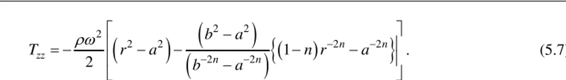
. (5.7)
These expressions are same as obtained by Dev [9] provided we put n = 1/N, which Dev
obtained by assuming the Norton’s law and Von-Mises yield condition.
Results and Discussion
In Fig. 1 curves have been drawn between 2
/ 4Y
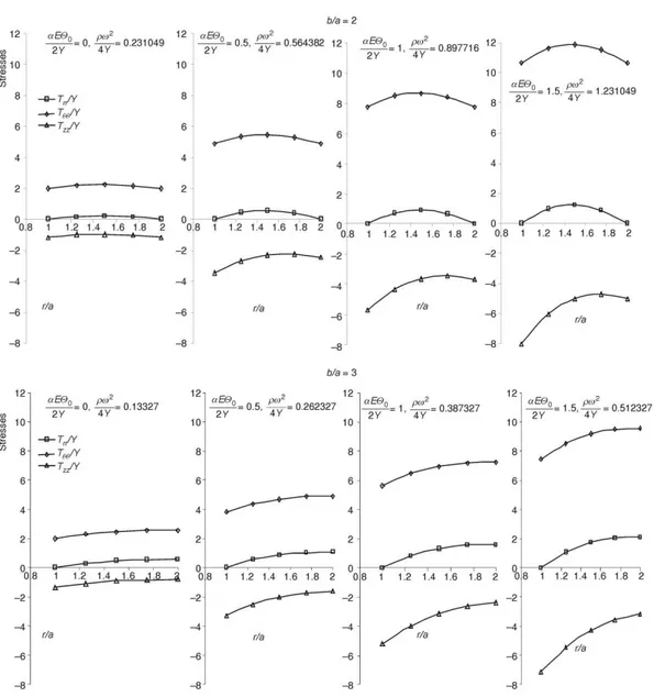
and E0/ 2Yto give yielding through the whole of the cylinder (fully plastic state) for different wall thickness ratios. It can be seen that with the increase of temperature, the cylinder having smaller radii ratios requires smaller angular velocity to become fully plastic as compared to cylinder having higher radii ratios. In Figs. 2 curves have been drawn for radial, circumferential and axial stresses with respect to radii ratios r/a, and for various combination of E0/ 2Y and 2/ 4Y. The circumferential stress increases with the increase in temperature. With increase in thickness ratio stresses must be decreased. The strain in the longitudinal direction as a function of temperature and the corresponding rotational speed (from Fig. 1) is plotted in Fig. 3, for cylinder having different thickness ratios. In the absence of thermal effects, the axial contraction increases with the increase in thickness ratios of the cylinder, but with the inclusion of temperature effects, it can be seen that cylinder having thickness ratio 2 gives greater axial contraction as compared to cylinder having thickness ratios 3, 4, 7 and 10. It is of interest to note that, at high temperature, axial contraction become greater for b/a = 2, then decrease for b/a = 3, remain almost the same for b/a = 4, then again increases for cylinder having thickness ratios b/a > 4. To see the combined effects of rotation and temperature, this
problems has been solved by using Simpson’s rule in eq. (5.1) and (5.3). For mild steel various values from [17] can be taken: Y 3 1041b/in2, E 3 1071b/in2and
6 0
7.5 10 per F
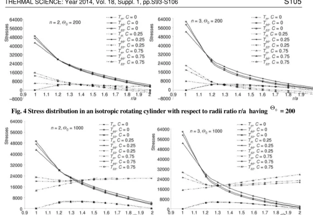
and 2/ 24200. In Figs. 4 and 5, curve have been drawn between the radial, circumferential and axial stresses for measure n = 2 and n = 3 respectively, with respect to radii ratio r/a. It has been seen that circumferential stress for incompressible material is maximum at the internal surface as compared to compressible material, which increase with the increase in temperature and measure n. It is noted in this context that Rimrott [3] showed similar results for plastic material without thermal effects, this is, if material tends to fracture by cleavage, it will begin as a sub-surface fracture close to the bore, because it is where the largest tensile stress occurs. This means that an increases in temperature increases the possibility of a fracture at the base at a lesser angular speed.
Fig. 1 Relation between 2
/ 4Y
Fig. 2 Distribution of Plastic stresses due to rotation and temperature through the wall of the cylinder
Fig. 4 Stress distribution in an isotropic rotating cylinder with respect to radii ratio r/a having 0 = 200
Fig. 5 Stress distribution in isotropic rotating cylinder with respect to radii ratio r/a having 0= 1000.
Conclusion
For elastic-plastic stage, it is seen that with the increase of temperature, the cylinder having smaller radii ratios requires lesser angular velocity to become fully plastic as com-pared to cylinder having higher radii ratios The circumferential stress becomes larger and larger with the increase in temperature. With increase in thickness ratio stresses must be decrease. For the creep stage, it is seen that circumferential stresses for incompressible materials maximum at the internal surface as compared to compressible material, which increase with the increase in temperature and measure n.
Acknowledgement
The author wishes to acknowledge his sincere thanks to Respected Prof. Simeon Oka (Editor-in- Chief Thermal Science) and Dr Vukman Bakić (Editor Thermal science) for his encouragement during the preparation of this paper.
Nomenclature
a,b- internal and external radii of the rotating cylinder, [m]
ij
T
e - ij stress [kgm -1s-2] strain rate tensors C - compressibility factor,[-]
u,v,w,- displacement components,[m]
Y -Yield stress, [kg
m
1s
2]Greek letters
- temperature,[0F]r
- Radial stress component (T
rr/
Y
),[-]
- Circumferential stress (T
/
Y
),[-]z
v - Poisson’s ratio, [-] Reference
[1] Nadai, A., Theory of flow and fracture, McGraw-Hill Book Company, New York, USA, 1960, pp. 60-61.
[2] Devis, E.A., Connelly, F.M., Stress distribution and plastic deformation in rotating cylinders of strain-hardening material, Jr. Appl. Mech., 26, 1959, pp. 25-30.
[3] Rimrott, F.P.J., On the plastic behaviour of rotating cylinder, J.Appl.Mech. 27(1960), pp. 309-315.
[4] Nadai, A., Theory of flow and fracture, McGraw-Hill, New York, USA, 1960, pp. 60-61. [5] Devis, E.A., Connelly, F.M., Stress distribution and plastic deformation in rotating
cylinders of strain-hardening material, Jr. Appl. Mech., 26, 1959, pp. 25-30.
[6] Rimrott, F.P.J., On the plastic behaviour of rotating cylinder, Jr. Appl. Mech., 27(1960), pp. 309-315.
[7] P.G. Hodge Jr. and Balaban M., elastic-plastic problem in a rotating cylinder, Int. J. Mech. Sci., Pergamon Press Ltd., 4(1962), pp. 465-476.
[8] Rimrott, F.P.J., Luke, J.R., Large strain creep of rotating cylinders, ZAMM, 41(1961), pp. 485-500.
[9] Dev. D., note on the Creep of a cylinder rotating about its axis, Indian, Jr., Math. Mech. 3, 1965, pp. 104-107.
[10] Seth,B. R., Measure concept in Mechanics, Int. J. Non-linear Mech., 1(1966), 1, pp. 35- 40. [11] Seth, B. R., Transition condition, the yield condition, Int. J. Non. Linear Mechanics, 15,
1970, pp. 279-285.
[12] Parkus, H., Thermo-elasticity, Springer-Verlag,Wien New York, 1976, pp. 119.
[13] Fung, Y.C., Foundation of solids Mech., Prentice Hall, Englewood Cliff, N. J. 1965, pp.23-29.
[14] Gupta , S.K., Elastic-plastic and Creep Transition of thick-walled cylinder Proceedings of International Symposium on Non- linear Mech. Kharagpur, India, 1980, pp.169-175. [15] Gupta, S.K., Dharmani, R. L., Creep Transition in Rotating Cylinders, Int. J. Pure Applied
Math.,15 (1981), 6, pp. 525-536.
[16] Hulsurkar, S., Transition theory of creep in shells under uniform pressure, ZAMM, 46, 1966, pp. 431-437.
[17] Johnson, W. and Mellor P.B., Plasticity for Mechanical Engineers. Von-Nostrand Reinfield Company, London,1971, pp. 140-149
[18] Pankaj, S. K. Gupta, Thermo elastic-plastic transition in a thin rotating Disc with inclusion, Thermal Science, 11(2007), 1, pp. 103-118.
[19] Pankaj Thakur, Elastic - Plastic Transition Stresses In Rotating Cylinder By Finite Defor-mation Under Steady- State Temperature, Thermal Science, 15(2011), 2, pp. 537-543. [20] Pankaj Thakur, Elastic-plastic transition stresses in a thin rotating disc with rigid inclusion
by infinitesimal deformation under steady state Temperature, Thermal Science, 14(2010),1, pp. 209-219.
[21] Pankaj Thakur, Creep Transition Stresses in a thin rotating disc with shaft by finite deformation under steady state temperature, Thermal Science, 14(2010), 2, pp. 425-436. [22] Pankaj Thakur, Creep transition stresses of a thick isotropic spherical shell by finite
defor-mation under steady state of temperature and internal pressure, Thermal Science 15(2011), Suppl. 2, pp. S157-S165.
Paper received: March 18, 2011 Paper revised: May 07, 2012