ABSTRACT: The optical solar relector is basically a mirror of second surface with low absorptivity/emissivity ratio and negligible degradation in the space environment, which makes it an excellent coating for thermal control of satellites. It works as a radiator and is used in particular parts of the external surfaces of the satellites in order to reject the undesirable heat to the deep space. In the Brazilian Space Programs, the radiators of the satellites are generally painted with special white paints in order to reject heat instead of the use of optical solar relector. The problem of white-ink radiators is the high degradation of the thermo-optical properties that happen over the useful lives. Thus, a process of manufacturing and assembly of optical solar relector was developed in Brazil. To validate this process in terms of mechanical and thermal properties, 3 types of optical solar relector radiators were manufactured, and their absorptivity and emissivity properties at the temperature of 23 °C were measured. Optical solar relector coupons were mounted on aluminum plates to perform vibration, thermal vacuum and thermal-shock tests. A study was also done to optimize the thickness of the glue to ix the structure of the satellite on the optical solar relector. It showed an excellent environmental stability and maintained its thermo-optical characteristics after the tests.
KeywoRdS: Solar radiator, Satellite thermal control, Solar absorptivity, Emissivity.
Assembly and Testing of a Thermal Control
Component Developed in Brazil
Marcos Galante Boato1, Ezio Castejon Garcia1, Marcio Bueno dos Santos2, Antonio Fernando Beloto2
INTRODUCTION
Artiicial satellites are equipment sent into space in order to perform a certain task, such as: meteorological studies, telecommunications, data collection for scientiic studies, etc. In the space environment, the satellite is exposed to extreme thermal conditions such as solar radiation, radiation that comes from the Earth (albedo and infrared), and a strong heat sink that is deep space, where the fund temperature is 4 K. herefore, the satellites are supposed to be protected from all thermal loads from space.
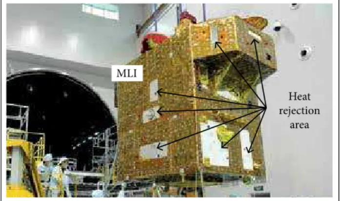
To protect the satellites, they are externally coated with thermal-control materials in order to isolate themselves of the external environment. Due to the absence of convective medium, heat exchange between the satellite and the space environment is made exclusively by radiation. One of the materials commonly used to coat the satellite is the thermal blanket known as multi-layer insulation (MLI) (Nagano et al. 2011). However, this coating cannot completely insulate the satellite, because of several devices which, by Joule efect, generate heat inside of the satellite. his heat raises the internal temperature, reaching above the acceptable limits, and it is necessary to eliminate the excess of heat through openings in the blanket. hese openings act as their heat rejection areas, radiating the heat of the equipment into deep space. Figure 1 shows the satellite CBERS-2B and the MLI with the respective openings for rejection of heat to deep space.
As all environments in satellites, the interaction is by radiation, and there is a high dependency of the thermal coating properties as a function of temperature. hus, these heat rejection areas, known as radiators, are coated with a material which has
1.Departamento de Ciência e Tecnologia Aeroespacial – Instituto Tecnológico de Aeronáutica – Divisão de Engenharia Mecânica – São José dos Campos/SP – Brazil. 2.Instituto Nacional de Pesquisas Espaciais – Laboratório de Integração e Testes – São José dos Campos/SP – Brazil.
good properties of emissivity and absorptivity (when exposed to direct solar radiation and albedo).
he Instituto Nacional de Pesquisas Espaciais (INPE) and the Instituto Tecnológico de Aeronáutica (ITA) have developed, manufactured, and qualiied an optical solar relector (OSR) to be used for thermal control of satellites. he OSR is a coating to be used as radiator for certain external surfaces of satellites. he aim is to reject heat that occurs in positions where it appears the incidence of solar radiation (direct and/or albedo).
In the design, thermal control coatings have to be resistant to the degradation efects of the space environment. Due to this degradation, there is an increase in the solar absorptivity and, thus, an increase occurs in the internal temperature of the satellite along its orbital life. he temperatures may exceed acceptable values, which can cause serious damage for equipment pieces in the satellite, consequently reducing the life of the mission.
The OSR-type heat radiators, as well as the white-ink radiators, are passive and used for thermal control of satellites. One of their characteristics is to have a lower absorptivity (αs) in the solar band if compared to the white-ink radiators, as well as a high emissivity (ε), which means that they can reject heat from the interior of the satellite to the deep space. he main feature is to present an extreme low degradation of thermo-optical properties if compared to other thermal control coatings (Gilmore 1994; Marshall and Breuch 1968).
As previously mentioned, the OSR is basically a mirror of second surface. It consists of a layer of thin silver ilm that is deposited on a surface of high-quality glass coverslip. A high ε in the infrared spectrum is related to the glass coverslip, which is transparent in solar band and substantially opaque in the infrared (spectrum of wave length below 4.5 μm) (Marshall and Breuch 1968). Furthermore, the thickness of the glass layer also inluences the ε value. he low α
s in the solar spectrum is
related to the thin silver ilm deposited on the glass coverslip (Greenberg et al. 1967).
What difers the OSR from other passive radiators is its negligible thermo-optical degradation of properties in relation to: atomic oxygen, protons, free electrons, and ultraviolet radiation. In addition, the OSR has a low degradation factor in relation to volatile organic photo-depositions that are generated by the outgassing from the satellite’s internal components and products of the satellite’s thrusters. that are generated by the outgassing from the satellite’s internal components and products of the satellite’s thrusters.
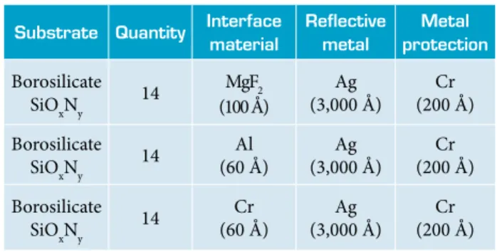
In this study, it was used a borosilicate glass with a thickness of 120 μm and dimension of 20 × 40 mm, supplied by the Shanghai Institute of Space Power Sources, in China. his material is doped with Cerium to avoid the appearance of color center in the glass surface due to ultraviolet radiation. hese coverslips were originally used as a protective coating of the Brazilian satellite solar cells, and this material has demonstrated a good environmental stability in space light.
EXPERIMENT
Silver has low adhesion to glass due to its lack of interaction with the active oxygen in the substrate (Benjamin and Weaver 1961). For greater adhesion between the substrate and the
silver ilm, it was deposited an interface layer to increase
this adhesion. As the metal interface might change the OSR
of the αs, 3 kinds of sample sets were made, each one with
different interfaces. Thus, there was the possibility to analyze which of the 3 interfaces might have the best adhesion for the thin ilm of silver and the best a
s /ε relation. hen, the adopted interface materials were: chromium (Iacovangelo et al. 2003), aluminum, and magnesium luoride (MgF
2) (Tanzilli
and Gebhardt 1996). In order to avoid the oxidation of silver in the terrestrial environment, a layer of Cr was deposited to protect the silver layer. hus, the inal mirror was composed of 3 layers (Fig. 2).
Figure 1. Satellite CBERS-2B and its heat rejection areas in the MLI. Heat rejection
area MLI
Protective layer (Cr) Reflective layer (Ag) Interface layer (Al, Cr or MgF2) Borosilicate coverglass
To conduct the proposed experiment, 3 series of deposits were made on the borosilicate coverslip glass. he study about the deposits was based on the veriication of optical and thermo-mechanical properties of the OSR for different interfaces. herefore, it was deposited on each set of substrates (Fig. 2; the thicknesses are described in Table 1) he layers of the ilms on the substrate surfaces were made with an apparatus which deposits thin ilms, called electron beam.
TheRmo-opTiCAl pRopeRTy meASuRemenTS For a thermo-optical surface to be considered a good passive radiator, its emissivity in the infrared spectrum has to be the highest as possible, and its absorption in the solar spectrum, the lowest. In this paper, the data from αs and ε were obtained from samples of OSR with diferent interfaces; so, it was possible to identify which sample had the best αs/ε ratio. To measure these properties, a Gier Dunkle Device was used for: a) normal solar absorptivity αs, which was done by the MS251 Solar Relectometer; b) hemispherical emissivity ε, by DB100 Infrared Relectometer. Table 2 shows the measurements for the 3 types of interfaces in the OSR. Initial measures have highlighted the diferences among the values of the αs for diferent samples.
Table 3 shows the ε values. In all 3 cases, no signiicant diferences were detected among the samples. What could be observed is the following: the interface layer deposited has high inluence on αs values, but it has low inluence on the
values of emissivity in infrared spectrum (εIR). In this test, it can be concluded that the OSR with the best αs/εIR ratio was the aluminum interface, with a value of εIR = 0.810 and αs = 0.026.
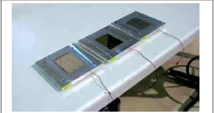
AppliCATion meThodS foR mATeRiAl evAluATionS he OSR with each interface type was glued on 3 aluminum plates, each one with dimensions of 150 × 150 × 10 mm and mass of 800 g. Each plate contained 6 coverslips with diferent types of interface (Fig. 3). he total mass of the 3 coupons was 2.4 kg, approximately.
For the OSR to be ixed on the aluminum plates, it was used the Dow Corning®glue RTV566, a qualiied resin-based silicon
for space. his glue was used for having a high elasticity, keeping its mechanical properties at high temperature gradients, and presenting low rates of outgassing at low pressures.
Each thickness of the glue, used to join the OSR to the aluminum plates, was calculated. he development of an equation was based on Volkersen’s formulation, which was expanded to Goland and Reissner (Chen and Nelson 1979). his equation takes into account the thermal expansion, elastic modulus of each material (glass and aluminum), and the shear modulus of the adhesive.
Another important consideration is that the shear stress is equal to 0 at the center of the assembly and increases gradually to the edge. Typically, the maximum shear stress occurs at the end of the bond and it is the item of most concern. Figure 4 shows how the expansion of the materials joined by bonded joints would be studied.
Equation 1 provides the maximum tension applied to the glue due to the thermal expansion of the materials (glass + aluminum). If this stress is higher or equal to the shear stress of the adhesive, it can break.
Substrate Quantity interface
material
Relective metal
metal protection
Borosilicate
SiOxNy 14
MgF2
(100 Å)
Ag (3,000 Å)
Cr (200 Å)
Borosilicate
SiOxNy 14
Al (60 Å)
Ag (3,000 Å)
Cr (200 Å)
Borosilicate
SiOxNy 14
Cr (60 Å)
Ag (3,000 Å)
Cr (200 Å)
Table 1. Borosilicate samples with their respective interfaces.
Cover slip interface normal solar absorptivity (αs)
MgF2 0.051 ± 0.005
Al 0.026 ± 0.005
Cr 0.237 ± 0.006
Table 2. Solar absorptivity for 3 interface types on the OSR.
Cover slip interface hemispherical emissivity (ε)
MgF2 0.812 ± 0.005
Al 0.810 ± 0.006
Cr 0.814 ± 0.005
Table 3. Data emissivity of 3 types of OSR.
(1)
where: τmax is the glue maximum stress; ω is the linear dilatation coeicient; ΔT represents the temperature gradient; G is the glue shear module; a means glue thickness; E
1 is the Young’s modulus
for glass; b
1 is the glass thickness; E2 is the Young’s modulus for
aluminum; b
2 is the plate thickness; x is the maximum distancefrom
The thickness of adhesive used was between 0.04 and 0.06 mm (measurement made through a device, with ±0.01 mm of error). In order to ensure uniformity in the glue thickness, a fabric screen of 44 wires/cm was used. Figure 6 illustrates the bonding process that ensures the glue thickness. To ensure a good uniformity of the glue under OSR, a weight was evenly placed on the OSR ater gluing.
Figure 5 shows the curve that relates the maximum stresses for each thickness of imposed glue. It was obtained by a Matlab program, developed in this study by using the shear strength data from the manufacturer. In the case of RTV566 glue, the limit pressure of maximum rupture is up to 3 MPa (provided by theoretical calculation). herefore, in Fig. 5, it is observed that, for borosilicate, the theoretical thickness is extremely small, which shows to be highly-elastic adhesive, suitable for the space requirements.
Figure 4. Differential expansion in plates. dl: gap relative to the
distance l for dilations between the glass and the aluminum base.
Figure 3. OSR coupons used in the environmental tests.
Figure 6. Printing screen being used to apply the RTV566 on aluminum plates.
Figure 5. Maximum tension to which the glue was requested in relation to its thickness.
Without axial tension
Glass
Glue
Aluminum base
l
l dl
x
Tension differential due to temperature
RTV566
2 × 10⁻⁶ 0
0 1 2 3 4
MN/m
2
4 × 10⁻⁶ 6 × 10⁻⁶ 8 × 10⁻⁶ 1 × 10⁵ m
ENVIRONMENTAL TESTS
RAndom viBRATion TeST
he samples were subjected to random vibration according to the levels speciied by the MIL-STD 883 — Method 2026 — K condition (Table 4). his test is intended to check the performance and mechanical strength of the bonding of the coverslips on OSR aluminum plate as well as the strength of adhesion of thin ilms of metal deposited on the borosilicate. his level was imposed for qualiication of the OSR as a component.
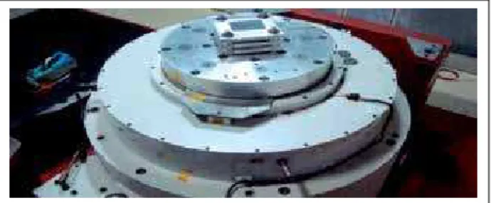
he sets of sample (OSR + aluminum plate) were installed on the electromechanical shaker (Fig. 7). To monitor the test, acceleration sensors were installed. One sensor was installed on the underside of the center of each coupon, 3 in total, focused on measuring the direction normal to the OSR. An additional sensor was installed in the circular adapter plate test of the set to the head of the electromechanical vibrator which belongs to
frequency range (hz) level
5 to 100 +6 dB/ILO
100 to 1,000 1.5 g2/Hz
1,000 to 2,000 −6 dB/ILO
Efective acceleration 44.8 grms
Duration 15 min
Direction Normal to the ORSs plane
the Laboratório de Integração e Testes (LIT) at INPE in order to control the applied excitation function.
he maximum excitation applied was 46.2 grms. he responses have reached in 53.1 grms for Cu; 55.5 grms for Al and 56.6 grms for MgF2, considering from the bottom plate. It is possible to verify that the 3 interface layers showed excellent adhesion of the silver ilm to the borosilicate glass ater the vibration tests. here was no delaminating of the silver from the glass surface. Furthermore, visual inspection was done, and it was found that there were no other damages, neither in the OSR, nor in the bonding.
Figure 7. Set of coupons installed for vibration testing.
Figure 8. Coupons inside the LIT Thermal-Vacuum Chamber #1.
TheRmAl-vACuum TeST
he test in the thermal-vacuum chamber simulates the space environment, in which the satellite will be exposed. For this test, it was used the 250 L # 1 thermal-vacuum chamber, which has a thermal shroud with temperature control operating from −180 to +150 °C and vacuum up to 10−7 Torr. his chamber
is part of the hermal-Vacuum Laboratory (TVL) at the LIT/ INPE. he infrastructure and test setup are presented in Fig. 8. The boundary conditions of the test were taken from the specification for the solar cells, from the classification of the AMAZON satellite program (Nagano et al. 2011). hese conditions present the exposure time to the maximum and minimum pressure levels as well as the quantity of temperature cycles. he speciication of the test is shown in Table 5.
Test parameters data
Number of cycles 4
Soak time 4 h
Maximum temperature 90 ± 5 °C
Minimum temperature −90 ± 5 °C
Vacuum chamber pressure Below 10−5 Torr
Table 5. Parameters for the test in thermal-vacuum chamber.
he use of these coupons previously used in vibration tests served as a method to check for potential problems that could arise from the vibration test (satellite launch simulation). hus, any problem could be magniied during the thermal vacuum test and then could be checked ater this.
his test aimed to verify possible cracks caused by OSR diferential thermo-dilation, delamination of thin ilms of the metal borosilicate coverslip glass, as well as problems related to assembly with air bubbles in the glue, which could expand due vacuum and damage the radiator.
As the thermal-vacuum test setup, 2 thermocouples (type T) were installed on each coupon in order to provide the individual temperatures. hese thermocouples worked to guaranty the parameters for the temperature control system of the chamber during the test. Ater installation of the thermocouples, coupons were installed inside the thermal-vacuum chamber.
What difers the OSR from other passive radiators is its negligible thermo-optical degradation of properties in relation to: atomic oxygen, protons, free electrons, and ultraviolet radiation. In addition, the OSR has a low degradation factor in relation to volatile organic photo-depositions
Figure 9 shows the simulated curve profile during the thermal-vacuum test. he test began at the hot level in order to take advantage of the temperature of the coupons. This procedure aimed at reducing the duration of the test, facilitating the chamber operation (Almeida et al. 2006).
Hot soak
Time [h]
T
emp
er
at
u
re
Cold soak 4
4 −90 ± 5 °C
~20 °C 90 ± 5 °C
120
T
emp
er
at
u
re
[
oC]
100 80 60
20 –0 –20 –40
–80 –100
–120
Date and time
04/10/2013 05h00
04/10/2013 17h00
04/11/2013 05h00
04/11/2013 17h00
04/12/2013 05h00
04/12/2013 17h00
04/13/2013 05h00
04/13/2013 17h00
04/14/2013 05h00
04/14/2013 17h00 40
–60
TC01 TC02 TC03 TC04 TC05
Figure 10. Developed temperature proiles of the coupons in the thermal-vacuum test.
Figure 10 shows the graph of the temperature in each specimen during the hot and cold cycles. At the end of each cycle, only a merely operational stop occurred in the thermal cycling, without compromising the vacuum pressure.
At the end of the thermal vacuum test, a visual inspection was performed, and no damage was observed, neither in the OSRs, nor in the bonding. With this test, one can conclude that the OSR was successfully qualiied according to the AMAZON program.
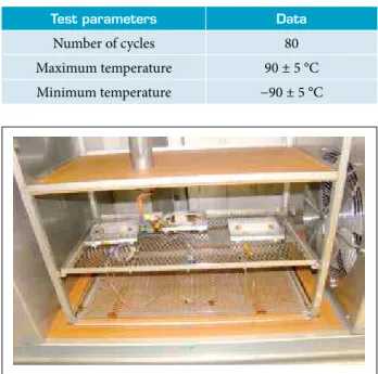
TheRmAl-ShoCK TeST
he thermal-shock test is an experimental method to check possible cracks on the glass and/or delaminating problems on the metal ilm due to high gradients of temperature imposed in the samples. For this test, it was used a thermal-shock chamber hermotron Model ATS-320-V-10-705 LIT/INPE.
he minimum and maximum thermal-shock limits were imposed according to predicted temperature levels for the OSR, once in orbit. Temperatures about 90 °C were set for the hot cases and −90 °C for the cold ones. he number of cycles for test was 80 thermal proiles. hese cycles were based on the qualiication process for solar cells of the AMAZON satellite program (Instituto Nacional de Pesquisas Espaciais 2013) as well as on MIL-STD-1540B military standard. he qualiication parameters for the thermal-shock test are presented in Table 6.
For the thermal-shock test, all thermocouples of the thermal-vacuum test described before were used. With these thermocouples, it was possible to measure the extreme temperatures and thermal transients of the coupons during the test.
The control of the thermal-shock chamber was directly connected with the measurements of the thermocouples. hus,
Test parameters data
Number of cycles 80
Maximum temperature 90 ± 5 °C
Minimum temperature −90 ± 5 °C
Table 6. Parameters of the thermal-shock test.
such temperatures were utilized to monitor the operation of the thermal-shock chamber elevator. When the coupons reached in a determined temperature level, the elevator was activated to take the coupons to the next compartment, and so on. Figure 11 shows the thermal-shock chamber with the coupons exposed in its elevator. Figure 12 shows the 80 cycles performed in the coupon qualiication test. In this igure, the developed temperature proile in the coupons is presented. Ater testing, visual inspection was performed on the samples, and no failure was observed.
Furthermore, visual inspections were done. It was observed there was not any damage, neither in the OSR, nor in the bonding.
By this test, it was concluded that the OSR has supported thermal-shock transient of 200 °C/min, and no damage was veriied in its structure.
RESULT ANALYSIS
Once completed the package of environmental and mechanical tests, the inal visual inspection and measurements of IR emissivity and solar absorptivity were made. For the inal qualiication, 3 main topics were considered:
Evaluation of the bonding process for OSR adhesion on base: it was taken into consideration the detachment of OSR aluminum plate in environmental and mechanical testing, and no damage was observed.
Evaluation of the process of ilms deposited on glass cover slip: aspects of delamination of the silver ilm from the glass surface were taken into consideration. For this case, no damage was observed too.
Evaluation of measurements of αs and ε, before and ater the
environmental and mechanical tests: there were not signiicant changes in the measurements.
CONCLUSION
he OSR, manufactured and tested at the LIT/INPE, proved to be an excellent tool for thermal control of satellites, due to
its characteristics of low degradation and excellent αs/ε ratio if
compared with white-ink radiators.
Other kinds of OSR, such as substrate of kapton or polytetrafluoroethylene, currently used by the Brazilian Space Program, could be developed too. In terms of mass, or maybe cost, these might be better; however, certainly in terms of degradation and αs/ε relation, the OSR developed in this study is one of the best.
The developed manufacturing process was very reliable: the glass was already qualified for space flight, and the deposition process has maintained the same characteristics during the manufacturing of each unit.
The interface layers showed the adhesion needed to withstand the stresses that the space environment demands. In addition, the manufacturing process has been studied to improve the adhesion of the silver film on the surface of borosilicate, introducing 3 kinds of interfaces among them. The 3 interface layers showed an improvement in the silver film adhesion on the glass, as could be seen in the vibration and climate tests: there was not delamination of the silver in glass surface. All thermo-optical measurements applied to the OSR showed the aluminum interface layer to have the lowest solar absorptivity; the others have resisted to all environmental tests.
he OSR coupons have demonstrated good stability of the thermo-optical properties ater being tested in the vibration, thermal-vacuum, and thermal-shock experiments. The stability in the large temperature range ensures their use in 90
T
emp
er
at
u
re
[
oC]
70
50
30
10
–10
–30
–50
–70
–90
–110
Date and time
04/24/2013 10h00
04/24/2013 15h00
04/24/2013 20h00
04/25/2013 01h00
04/25/2013 06h00
04/25/2013 11h00
04/25/2013 16h00
04/25/2013 21h00
04/26/2013 02h00
04/26/2013 07h00
TC01 TC02 TC03 TC04 TC05
REFERENCES
Almeida JS, Santos MB, Panissi DL, Garcia EC (2006) Effectiveness of low-cost thermal vacuum tests of a micro-satellite. Acta Astronaut 59(6):483-489. doi: 10.1016/j.actaastro.2006.03.003
Benjamin P, Weaver C (1961) The adhesion of evaporated metal ilms on glass. Proc Roy Soc Lond Math Phys Sci 261(1307):516. doi: 10.1098/rspa.1961.0093
Chen WT, Nelson CW (1979) Thermal stress in bonded joints. IBM J Res Dev 23(2):179-188. doi: 10.1147/rd.232.0179
Gilmore DG (1994) Satellite thermal control handbook. Vol. 1: Fundamental technologies. 2nd ed. El Segundo: The Aerospace Corporation Press.
Greenberg SA, Vance DA, Streed ER (1967) Low solar absorptance surface with controlled emittance: a second generation of thermal control coatings. In: Heller GB, editor. AIAA Progress in Astronautics and Aeronautics: thermophysics of spacecraft and planetary bodies. Vol. 20. New York: Academic Press. p. 297-314.
Iacovangelo CD, Pan Y, Wei C, Chen M, inventors; Lockheed Martin Corporation, assignee. 2003 Jul 1. Optical solar relector. United States Patent US 6,587,263.
Instituto Nacional de Pesquisas Espaciais (2013) AMAZONIA 1. Satellite Environmental Speciication. A820000-SPC-009/04.
Marshall KN, Breuch RA (1968) Optical solar relector: a highly stable, low α
s/ε spacecraft thermal control surface. J Spacecraft Rockets
5(9):1051-1056.
Nagano H, Ohnishi A, Nagasaka Y (2011) Development of a lightweight deployable/stowable radiator for interplanetary exploration. Appl Therm Eng 31(16):3322-3331. doi: 10.1016/j. applthermaleng.2011.06.012
Tanzilli RA, Gebhardt JJ, inventors; The United States of America as represented by the Secretary of the Air Force, assignee. 1996 Jul 30. Optical solar relector. United States Patent US 5,541,010. space vehicles, once predicted for conditions similar to the
AMAZON Project.
he chosen adhesive (RTV566) has demonstrated mechanical and thermal stability due to diferential expansion that occurred between the OSR and aluminum. he thermo-optical tests have shown that the deposited adhesion layer interferes with the values of αs: the best option is the aluminum interface, which
provides the best αs/ε relation.
hus, it can be concluded that the process of OSR development can be a good option in the manufacture of thermal radiators,
being used as a tool for the thermal control of satellites. his qualiication process has been well done at the LIT/INPE.