PROGRAMA DE PÓS-GRADUAÇÃO EM ODONTOLOGIA NÍVEL: DOUTORADO
ÁREA DE CONCENTRAÇÃO: PRÓTESE DENTÁRIA
AVALIAÇÃO DA PRECISÃO DOS MODELOS DE GESSO OBTIDOS POR DIFERENTES TÉCNICAS DE MOLDAGEM PARA PRÓTESES MÚLTIPLAS
IMPLANTO SUPORTADAS
ANNE BUSS BECKER
ANNE BUSS BECKER
AVALIAÇÃO DA PRECISÃO DOS MODELOS DE GESSO OBTIDOS POR DIFERENTES TÉCNICAS DE MOLDAGEM PARA PRÓTESES MÚLTIPLAS
IMPLANTO SUPORTADAS
Tese apresentada ao Programa de Pós-Graduação em Odontologia da Faculdade de Odontologia da Pontifícia Universidade Católica do Rio Grande do Sul como requisito para obtenção do titulo de Doutor em Odontologia, na área de concentração de Prótese Dentária.
ORIENTADOR: Prof. Dr. HUGO MITSUO SILVA OSHIMA
ANNE BUSS BECKER
AVALIAÇÃO DA PRECISÃO DOS MODELOS DE GESSO OBTIDOS POR DIFERENTES TÉCNICAS DE MOLDAGEM PARA PRÓTESES MÚLTIPLAS
IMPLANTO SUPORTADAS
Linha de Pesquisa: Técnicas e Aparelhos em Odontologia
Tese apresentada ao Programa de Pós-Graduação em Odontologia da Faculdade de Odontologia da Pontifícia Universidade Católica do Rio Grande do Sul como requisito para obtenção do titulo de Doutor em Odontologia, na área de concentração de Prótese Dentária.
BANCA EXAMINADORA:
Profª Drª Regênio Mahfuz Herbstrith Segundo
Prof Dr Claudio Figueiró
Profª Drª Leticia Borges Jacques
AGRADECIMENTOS
A Deus pela vida, fé, caminhos, esperanças. A fé em Deus nos faz crer no incrível, ver o invisível e realizar o impossível.
Aos meus pais Carlos Celeste Lena Becker (in memoriam) e Maria Tereza Becker, obrigado pelo dom da vida, pelas lições de amor, pela paciência, carinho, amor incondicional.
Ao meu esposo Carlos Alexandre Souza Bier, pelo apoio incondicional para que continuasse me aperfeiçoando, pelo exemplo de pessoa, pai, professor.
Aos meus filhos Lucca Becker Bier e Clara Becker Bier, agradeço por me ensinarem a ser uma pessoa melhor a cada momento. Lucca obrigado por eu ter graça de viver com esta pessoa tão amável, carinhosa, cheia de ternura. Clara hoje você faz parte do nosso sonho, logo estará em nossos braços.
Aos meus irmãos Leandro Buss Becker e Cristiane Buss Becker obrigado pelo companheirismo, apoio e experiências trocadas durante todos estes anos. Leandro você é um exemplo de pessoa, pesquisador e professor. Crika admiro sempre tua alegria, persistência e entusiasmo.
A coordenadora do Programa de Pós Graduação da PUCR, Prof. Dra. Ana Maria Sphor, pelas experiências compartilhadas, por sua dedicação e amor à causa Acadêmica.
Aos colegas de Doutorado da PUCRS pelos inúmeras experiências compartilhadas.
Aos meus colegas da UNIFRA, pelo companheirismo, experiências compartilhadas. Obrigada a coordenadora Ana Maria Chagas por ter permitido que eu continuasse meus estudos
A Pontifícia Universidade Católica (PUCRS), por ter possibilitado o acesso a este programa de Pós Graduação.
Ao Programa de Pós Graduação em Ciências Odontologicas da Universidade Federal de Santa Maria, UFSM, por ter permitido a utilização da lupa estereomicroscopica.
RESUMO
O objetivo deste estudo foi avaliar a precisão dos modelos de gesso sobre implantes obtidos por meio da técnica de moldagem de arrasto, na qual utiliza transferentes quadrados, utilizando diferentes materiais para união dos transferentes por meio de dois modelos experimentais in vitro.
Inicialmente avaliou-se a precisão dos modelos de gesso obtidos por meio de duas diferentes técnicas de moldagem: Grupo 1 – Moldagem de arrasto sem união dos transferentes e Grupo 2 – Moldagem de arrasto com união dos transferentes em resina acrílica autopolimerizavel para próteses implanto suportadas. Um bloco de alumínio com 2 análogos do implante minipilar 4.1 (Neodent SA Curitiba, Parana, Brasil) foi fabricado, sendo um analogo posicionado em angulo reto com o topo da superficie e outro inclinado a 65 graus lateralmente. Uma infraestrutura em liga NiCr, foi fabricada. As moldagens foram realizadas com moldeira individual em resina acrilica e o material utilizado foi o polieter. Dois grupos foram formados: Grupo 1 – sem união e Grupo 2 – com união em resina acrilica. Foram obtidos 5 modelos de gesso por grupo totalizando 10 modelos. A distância entre a infraestrutura e os analogos foi mensurada (gap vertical) por meio do programa (AxionVision 4.8.1, Zeiss; Carl Zeiss, Jena, Germany) acoplado a lupa estereomicroscopia. Os resultados mostraram diferenças significantes entre os grupos 1 e 2, com menores valores de gap para o grupo com união em resina acrilica (p=0,021). Na avaliação por implante, maiores valores foram obtidos para implantes inclinados (65 graus lateralmente) pela tecnica sem união (p=0,013).
com um grupo controle (bloco de alumínio com dois análogos do implantes minipilar 4.1 paralelos entre si). O material utilizado para as moldagens foi o poliéter. Sete grupos foram formados: G1 – grupo controle, G2a – sem união e gesso Fujirock, G2b – sem união e gesso Zero Stone, G3a – união com resina acrilica e gesso Fujirock, G3b – união com resina acrilica e gesso Zero Stone, G4a - união com resina bisacrilica e gesso Fujirock, G4b - união com resina bisacrilica e gesso Zero Stone. Foram avaliadas as distancias entre os implantes por meio do programa (AxionVision 4.8.1, Zeiss; Carl Zeiss, Jena, Germany) acoplado a lupa estereomicroscopia. Os resultados mostraram diferenças significante entre as distancias do G1 - grupo controle e os grupos: G2a - sem união e gesso Fujirock (p=0.010), G2b- sem união e gesso Zero Stone (p=0.015) e G4b - união com resina bisacrilica e gesso Zero Stone. (p=0.007). Não houve diferenças significantes entre o G1 - grupo controle e os grupos G3a - união com resina acrilica e gesso Fujirock (p=0.178), G3b- união com resina acrilica e gesso Zero Stone (p=0.288), G4a - união com resina bisacrilica e gesso Fujirock (p=0.531). Conclui-se que os grupos sem união dos componentes produziram maiores distorções quando comparadas ao grupo controle.
DESCRITORES1
Implantes Dentários, Sulfato de Cálcio, Materiais para Moldagem Odontológica, Técnica de Moldagem Odontológica, Modelos Dentários
______________________
1
ABSTRACT
The aim of this study was to evaluate the accuracy of implants master casts obtained by
pick- up techniques with an open custom tray using squared impression copings, using several union transfers on two, in vitro, experimental models.
First, the dimensional accuracy of implants master cast was evaluated, and two impression techniques: G1- squared impression copings (S) and G2- splinted squared copings, using dental floss and acrylic resin for implant-supported prostheses. An aluminum block with 2 implant-abutment analogs were fabricated (one implant was made at right angle to the top surface “A” and the other was angulated 65 degrees sideway “B” and a frameworks in type NiCr was used. Impression was performed using acrylic resin tray and polyether impression material. Specimens were divided in two experimental groups: squared impression copings (S) and splinted squared copings. Five casts were made per group, in total of 10 casts. A software was used in order to analyze and to record the vertical gap between reference framework and analogs in duplicate casts, connected to a stereomicroscope. Results showed statistical differences between group 1 and 2, with lower levels of gaps in the splinted squared copings, using dental floss and acrylic resin compared to the squared impression copings (P=.021). On the implant evaluation, higher values were obtained for the implant angulated 65 degrees with squared impression copings technique (P=.013).
Seven groups were formed: G1 – control group; G2a – Squared impression copings, poured with a die stone GC Fujirock EP; G2b – Squared impression copings, poured with a die stone Zero Stone G3a – Splinted squared copings using dental floss and acrylic resin poured with a die stone GC Fujirock EP; G3b- Splinted squared copings using dental floss and acrylic resin - poured with a die stone Zero Stone; G4a - Splinted squared copings using dental floss and bisacrilica resin - poured with a die stone GC Fujirock EP; G4b - Splinted squared copings using dental floss and bisacrilica resin poured with a die stone Zero Stone. The distances between the analogs of each specimen were measured, using a software, connected to the stereomicroscope.
Results presented statistical differences between the distances of G1 and G2a (p=0.010), G2b
(p=0.015), G4b (p=0.007). No statistical differences were found between G1 and G3a (p=0.178),
G3b (p=0.288), G4a (p=0.531). Splinted squared copings poured with a die stone GC Fujirock
EP produced cast most similar to the control Group.
DESCRIPTORS2
Dental Implants, Calcium Sulfate, Dental Impression Materials, Dental Impression Technique, Dental Models
______________________
2
Lista de Abreviaturas e siglas RA: resina acrílica
µm: micrometro mm: milímetro
LISTA DE ANEXOS
Anexo A: Aprovação pela Comissão Científica e de Ética da Faculdade de
SUMÁRIO
INTRODUÇÃO GERAL ... 19
OBJETIVOS ... 24
Objetivo Geral ... 24
Objetivo Específico ... 24
ARTIGO DE PESQUISA 1 ... 25
Abstract ... 28
Introduction ... 30
Material e Methods ... 31
Results. ... 34
Discussion ... 35
References ... 39
ARTIGO DE PESQUISA 2 ... 45
Abstract ... 46
Introduction ... 49
Material e Methods ... 50
Results ... 53
Discussion ... 54
References ... 57
DISCUSSÃO GERAL ... 64
CONCLUSÕES ... 71
REFERÊNCIAS BIBLIOGRÁFICAS ... 72
INTRODUÇÃO GERAL
O crescente interesse dos pacientes pela reposição de seus dentes perdidos e a continua evolução dos implantes osseointegrados, proporcionam uma valorização da odontologia restauradora. O sucesso das restaurações protéticas com implantes dentários está diretamente ligado a adaptação passiva entre prótese e implante e uma adequada distribuição das forças mastigatórias (1). O problema da passividade entre infraestruturas metálicas e barras sobre implantes merecem atenção, uma vez que a conexão forçada da estrutura metálica da prótese implanto retida pode resultar em problemas biológicos como micro-fraturas do tecido ósseo e zonas de isquemia marginal ou problemas mecânicos que incluem o afrouxamento dos parafusos ou a fratura dos componentes protéticos (2). Isto é importante para o sucesso a longo prazo da sobrevida dos implantes e da preservação do tecido ósseo (3). Existem diferentes variáveis clínicas e laboratoriais que podem afetar a acurácia dos modelos de implantes como as diferentes técnicas de moldagem, diferentes materiais, propriedades e técnicas para vazamento dos gessos, tolerância das máquinas dos componentes protéticos, angulação e profundidade dos implantes, tipos de fundição (4) (5). Várias técnicas de moldagem foram desenvolvidas como tentativa de obter um modelo de trabalho que resultará maior precisão clinica para o assentamento das próteses múltiplas implanto retidas.
A técnica do casquete cônico também denominada de moldagem de transferência utiliza moldeiras fechadas, transferentes cônicos que possibilitam a sua permanência na cavidade bucal após a remoção do molde. Esta técnica apresenta uma menor precisão devido a ausência de paralelismo dos pilares, deformação do material de moldagem e a presença de ar entre o molde e o transferente impedem o perfeito assentamento do transferente (1).
Os componentes quadrados possuem paredes paralelas e áreas retentivas para que fiquem capturados no interior do molde sem se movimentarem. Existe a possibilidade de girar os componentes no interior do molde, quando se parafusa a réplica ou análogo, assim a união dos tranferentes e esplintagem dos componentes tem sido muito bem defendida em diversos trabalhos para moldagem de próteses sobre implantes múltiplos (1).
Diferentes materiais são utilizados para união dos transferes, como a resina acrílica (RA) (fio dental + RA Duralay), fio dental + RA Pattern (6), RA com extensão nas distais para retenção (7), RA com espera de 17 min, tempo de maior contração, secção e nova união (8), resina acrílica de dupla polimerização (AccuSet -EDS,. Hackensack, NJ), (9) resina acrílica fotopolimerizada (lâminas de resina acrílica) (10), barras pré polimerizadas (RA ou resina composta) (10), resina polimerizada por luz, fios de ortodontia + RA, silicona de condensação, gesso tipo I para moldagem (11), jateamento dos tranferentes e aplicação do adesivo do poliéter (7).
A resina acrílica autopolimerizavel é um dos materiais, apresentando ótimos resultados mais utilizado nestes estudos (6, 7, 12, 13). Uma das desvantagens apresentadas deste material é a alta contração de polimerização. As resinas bisacrílicas são materiais desenvolvidos para minimizar os efeitos negativos da resina acrílica, além de ser mais fácil de usar, devido possuir um cartucho automisturador, na qual já nos dá as proporções corretas, possui menor contração de polimerização e maior resistência.
obtidas: α- hemidrato, α- hemidrato modificado e o β- hemidrato (14). O α- hemidrato modificado é fabricado quando pela fervura da gipsita em uma solução aquosa de cloreto de cálcio e cloreto de magnésio a 30%. Este processo permite que os pós produzidos sejam partículas mais lisas e densas entre os três tipos. Este é denominado de gesso natural. É possível produzir sinteticamente os α- hemidratos e β- hemidratos a partir dos subprodutos ou produtos residuais da produção do ácido fosfórico. Gesso artificial. O produto sintético é geralmente muito mais dispendioso do que a produção a partir da gipsita natural, mas quando o produto é produzido de forma adequada suas propriedades são iguais ou excedem aquelas dos gessos naturais. Podermos classificar os gessos quanto a sua expansão: sem expansão (zero de expansão) e gessos com expansão (superior a 0,01%). O Gesso Fujirock segundo o fabricante possui 0,08% de expansão, o Zero Stone possui segundo o fabricante 0,0% de expansão.
O gesso dever ter as seguintes propriedades: compatibilidade com os materiais de moldagem, precisão dimensional, reprodução de detalhes, adequado tempo de trabalho, mínima expansão, alta resistência a compressão, resistência a fratura e abrasão , dureza de superfície, facilidade de manipulação, ausência de toxicidade, e resistência transversal (15).
Os principais requisitos para os materiais dos modelos odontológicos são dureza superficial e mínima expansão. Várias tentativas dos fabricantes tem sido feitas pra melhorar estes requisitos, como controle da temperatura da calcinação, tempo de queima, procedimento de pulverização para a obtenção do pó (14).
dimensional (15-17). O Gesso tipo IV é o material mais utilizado para a confecção de modelos de trabalho.
Na busca de um trabalho com exatidão, busca-se observar todas as variáveis envolvidas nas etapas de confecção, sem desprezar nenhum ponto que possa servir de elo fraco da cadeia. Sendo assim além da utilização de materiais e técnicas de moldagem adequadas para moldagem de implantes múltiplos devemos observar os materiais para obtenção dos modelos de trabalho pra que o objetivo almejado de uma infra estrutura com assentamento passivo seja obtida.
Quatro hipóteses nulas foram testadas:
1) Não existem diferenças na precisão dos modelos de gesso quando utilizada a técnica de moldagem de arrasto, sem união dos componentes e unidos com resina acrílica em implantes perpendicular a superfície e inclinados a 65°.
2) Não existe diferenças na precisão dos modelos de gesso quando utilizada a técnica de moldagem de arrasto em implantes perpendicular a superfície e inclinados a 65°. 3) Não existe diferenças na precisão dos modelos de gesso quando utilizada a técnica de
moldagem de arrasto, quando utilizada ausência de união dos transferentes e diferentes materiais de união dos componentes, união com resina acrílica e união com resina bisacrílica nanoparticulada em implantes paralelos.
OBJETIVOS Objetivo geral
Avaliar a precisão dos modelos de gesso obtidos pela técnica de moldagem de sacar ou de arrasto, com a utilização de moldeira aberta e utilizando diferentes materiais de união dos componentes quadrados.
Objetivos específicos
Avaliar a precisão dos modelos de gesso utilizado a:
1) Técnica de moldagem de arrasto sem união dos componentes e unidos com resina acrílica em implantes perpendicular a superfície e inclinados a 65°.
2) Técnica de moldagem de arrasto em implantes perpendicular a superfície e inclinados a 65°. 3) Técnica de moldagem de arrasto, quando utilizada ausência de união dos transferentes e diferentes materiais de união dos componentes, união com resina acrílica e união com resina bisacrílica nanoparticulada em implantes paralelos.
CAPÍTULO I
ARTIGO 1
Title: Angulation effect and impression techniques or the accuracy of master cast using metal framework
Title: Angulation effect and impression techniques or the accuracy of master cast using metal framework
Author names and affiliations:
Anne Buss Becker1, Hugo Mitsuo Silva Oshima2 1
Graduate Program of Dental School, PUCRS, 2School of Dentistry, PUCRS;
Abstract:
Statement of problem. Accurate recording of implant location is required in every implant-supported prostheses. Implant angulation, which is inevitable in several clinical situations, could affect the impression accuracy.
Purpose. This in vitro study aimed to compare the accuracy of implants master cast, and two impression techniques: squared impression copings and splinted squared copings, using dental floss and acrylic resin (Pattern Resin) for implant-supported prostheses placed with different angles, and the effect of the angulation of the 90° and 65°.
Material and methods. An aluminum block with 2 implant-abutment analogs were fabricated (one implant was made at right angle to the top surface and the other was angulated 65 degrees sideway). Frameworks in type NiCr alloy. Polyether impression material was used for all impression with acrylic resin tray. Two experimental groups were formed: squared impression copings and splinted squared copings using dental floss and acrylic resin - Pattern Resin. Five casts were made per group, in total of 10 casts. The software AxionVision 4.8.1, was used in order to analyze and to record the vertical gap between reference framework and analogs in duplicate casts that received the images from a camera coupled to a stereomicroscope, observed at 10X magnification. The gap values were analysed using analysis of variance (ANOVA). The level of significance was set at 5%.
Conclusions. Under the limitations of this study, the accuracy of the splinted squared impression technique was superior to squared impression copings, for implants presenting different angulation.
CLINICAL IMPLICATIONS
INTRODUCTION
Dental implants, which do not present a periodontal ligament, are not able to compensate not even minor misfits of the superstructure.1 Therefore, recording a correct 3-dimensional orientation rather than surface detail is necessary to avoid biologic and technical complications. 2 It is appropriate to ensure accurate reproduction of the implant relationship in the working cast for the fabrication of a passively fitting framework. The accuracy of the master cast depends on the type of impression material, the implant impression technique and the accuracy of the die.3 Whereas the influence of different impression materials appears to be less critical, impression techniques are considered as a major factor that could influence impression accuracy.3,4
Several implant impression techniques, such as splint, pick- up and transfer techniques, have been introduced and investigated regarding to their accuracy. Other factors related to the accuracy of the implant impression, including the angulation and implants depht, have also been studied. The chosen of an indirect technique, which uses tapered transfer copings and a closed stock tray, is controversial because while it requires less difficult clinical procedures it probably
involves greater instability. 5,6 Likewise, the advantages of splinting and of each splinting technique used in the direct technique, have not been established at the moment. 7 One advantage of the direct technique, which uses square transfer copings with an open custom tray, would be
greater transfer precision because of the splinting stability during the impression removal and
analog connection. 8,9
When multiple implants are placed with different angles, the distortion of the impression material on removal may increase. Two studies reported less accurate impressions using angulated implants instead of straight implants using an experimental cast with 4 or 5 implants. 6,10
implants.
Two null hypotheses were tested. Fisrt, there are no differences in accuracy of implants master cast when used two impresson technique: square impression copings and splinted square coping using dental flos and acrylic resin: Patter resin for implant implant-supported prostheses placed with different angles. Second, there are no differences in accuracy of implants master cast when used to implant positioned at 90° in relation to the surface of the matrix and 65°.
The purpose of this in vitro study was to investigate the angulation effect and impression techniques (squared impression copings, squared impression copings splinted using dental floss and acrylic resin) on the accuracy of master cast using metal framework, compared to the control group.
MATERIAL AND METHODS
Fabrication of the Master Cast
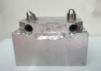
An aluminum block has 20 mm (width) x 20 mm (height) x 30 mm (length), presenting two holes 20 mm apart from each other was used to serve as a clinically relevant simulation. Two minipilar 4.1 titanium analogs (Neodent SA Curitiba, Parana, Brazil) were placed at 65° sideways and 90° in relation to the surface of the aluminum block and secured by screws (Fig 1). The stopper block presents a lateral and circling the two mm receded, which acts as stop device for trays.
Fabrication of de framework
Fabrication and prepare of Custom Trays
Two custom autopolymerizing acrylic resin trays (Jet- Clássico, Campo Limpo, SP, Brazil) were fabricated using the aluminum block in this study. One of them was used for the squared impression copings technique and the other one was used for the splinted squared
copings using dental floss and acrylic resin. These trays had a 3 mm relief for impression
material, with 2 spaces to allow access to the coping screws.
Tray polyether adhesive (3M ESPE, Seefeld, Germany) was applied thinly and evenly
over the inner surface of each tray, extended approximately 3 mm onto the outer surface of the
tray, along the periphery. The adhesive was allowed to dry for 15 minutes before the impressions
were made.
Transfer Procedures
Two groups with 5 casts each were formed.
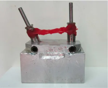
Group S - Squared impression copings. (Figure 3)
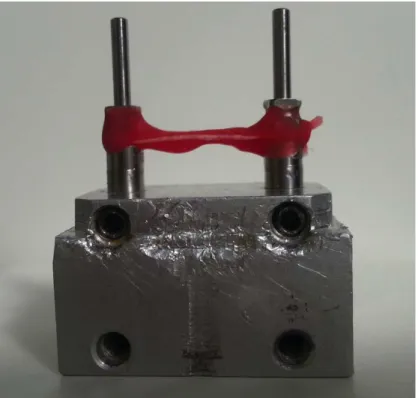
Group SS - Splinted squared copings using dental floss and acrylic resin - Pattern Resin (GC
Europe, Leuven, Belgium). (Figure 4)
Soft viscosity polyether (Impregum Penta Soft; 3M ESPE, Seefeld, Germany) was the
impression material chosen for all transfer procedures.13,14 Automatic mixing and dispenser Pentamix 2 (3M ESPE, Seefeld, Germany) was used to standardize all mixtures. Polyether was injected around the transfer copings and placed inside the custom tray using the dispenser. The
tray was seated on the aluminum block with gentle pressure until the lateral and circling stops contacted the base of the aluminum block. The impression material was allowed to set for 12 minutes from the start of mixing; the manufacturer’s setting time was doubled to compensate a
delayed polymerization reaction at room temperature rather than at mouth temperature. A
This was enough to force the excess material to flow out and to maintain constant pressure
throughout the working time.
Transfer Copings
Group S: Squared impression copings (Fig. 3). The squared impression copings were adapted to the abutment analogs on the aluminum block using 10 Ncm of torque.
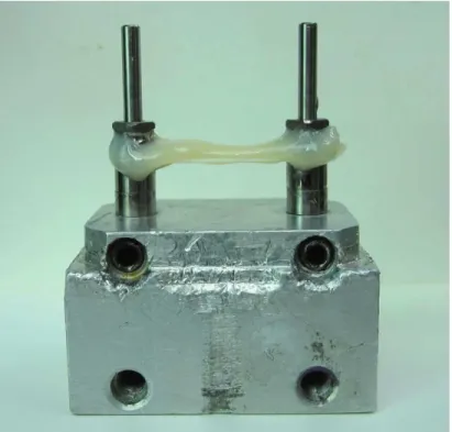
Group SS: Splinted squared copings with dental floss and acrylic resin – Pattern (GC Europe,
Leuven, Belgium) (Fig. 4). The squared impression copings were adapted to the abutment analogs on the aluminum block using 10 Ncm of torque. Dental floss was adaptaded to squared impression copings, and the autopolymerizing acrylic resin (Pattern GC Europe, Leuven, Belgium) wraped around the copings and dental floss.
Specimen Preparation
After the impression material polymerization impression copings were unscrewed and the tray was separated from the aluminum block. The minipilar abutment analogs (Neodent SA Curitiba, Parana , Brazil) were fit to the impression copings using 10 Ncm of torque while the copings were held with a hemostatic forceps to prevent the squared coping from rotating inside the impression. 16 This procedure was not necessary for the modified squared technique, but it was performed in order to standardize the methodology.
The impressions were poured with a die stone Zero Stone (Dentona AG, Dortmund, Germany), 30 minutes after the impressions were made. A ratio of 23 ml of distilled water to 100 g of stone was used, and the stone was manually mixed for 15 seconds to incorporate the water.
Then mechanically mixed under vacuum for 45 seconds with a digital vacuum spatulator
(Turbomix EDG Equipment, São Carlos, SP, Brazil). All mixes were vibrated into the
impression. The stone casts were allowed to set for 2 hours before separation from the
All casts obtained were stored at room temperature for a minimum of 2 weeks before measurement. 16
Measurement of accuracy
The standard framework was seated on each cast and a titanium screw was tightened in
analog right and left to a 10 Ncm using torque driver (Neodent SA Curitiba, Parana, Brazil) for measurements of implant analog-framework interface gaps. The examiner was calibrated and blinded to all definitive casts measurements
After 7 days, these measurement were analyzed using software (AxionVision 4.8.1,
Zeiss; Carl Zeiss, Jena, Germany) that received the images from a camera (AxionCam ICc3,
Zeiss; Carl Zeiss, Jena, Germany) coupled to a stereomicroscope (Zeiss Discovery V20; Carl
Zeiss, Jena, Germany), observed at 10X magnification.
Vertical gaps of the analogs were assessed in anterior directions for each cast.
Demarcations were made in the center of each analog to standardize the vertical gaps values. For
each image, 4 vertical gaps values at the same point were reading between implant analog-framework interface 90° and 65° .
Statistical analysis
Gap values were analyzed using the SPSS/PC Statics 22 software (SPSS Inc., Chicago, IL, USA), using analaysis of variance (ANOVA). The level of significance was set at 5%.
RESULTS
Table 2 shows the mean, standard deviations of abutment/framework interface gaps between groups S and SS combined sideways. Significant differences were detected between Group S - squared copings and Group SS -Splinted squared copings techniques (P = .021).
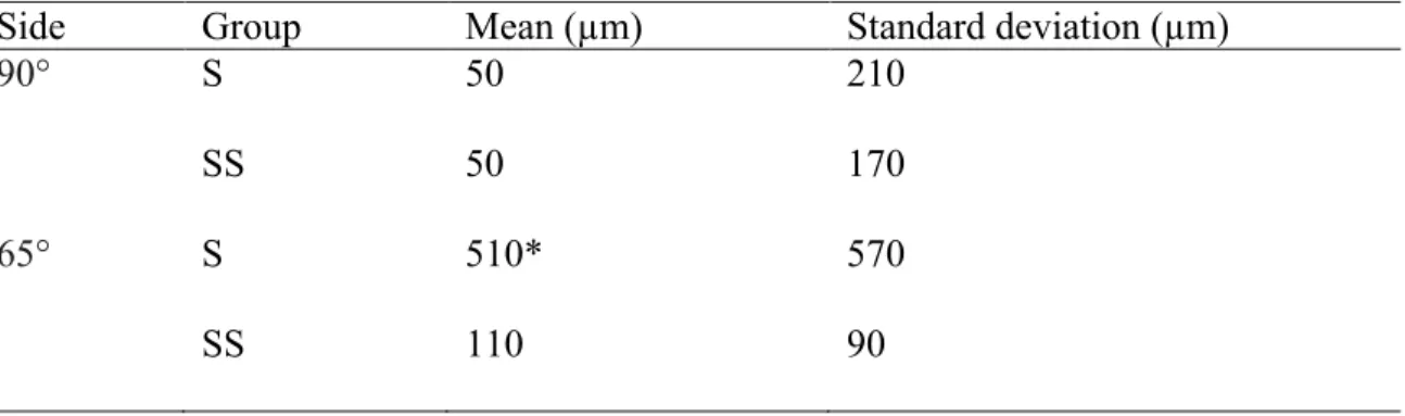
Table 3 shows the mean, standard deviations, of abutment/framework interface gaps for each side 90° and 65°. Significant differences were found between side 65° (Group S) - squared copings and others (P =.013).
DISCUSSION
The master cast reproduces the intraoral position of the implants surrounding by osseous tissue and soft tissues as accurately as possible, to allow the fabrication of passively fitting prostheses and, consequently, eliminating the strain on the supporting components around the bone. 17
A passive fit occurs when all the surfaces of the implant and prosthesis are aligned with no force application and when the gap formed between the metallic framework and implants are within the limits established by science (111 µm or 0.11 mm). 18 A perfect fit occurs when all the matching surfaces of the implant and prosthesis are in alignment and in contact with no force application. 19 In order to identify a passive fit, the master cast used in this study was fabricated using a previously completed metal framework.
Several factors surround the the implant transfering position from mouth to cast, including the implant connection type and impression coping design, the number of implants and angulation, the impression technique and the impression material. Whereas the influence of different impression materials appears to be less critical, impression techniques are considered as a major factor that could influence impression accuracy. 3,4,20
techniques. The transfer techniques implant impression copings can be repositioned into the impression material after impression making with a tapered impression copings associated to closed tray (indirect, transfer) technique. On the other hand, in the pick-up technique, the square impression copings are unscrewed of the implant after the setting of the impression material and removed from the mold, using an opened tray. Both techniques and their modifications are used to achieve implant impression accuracy.
The null hypothesis of the present study, stating that the accuracy of casts would not be affect by the impression technique, was rejected. Significant differences were detected between the square copings and splinted squared copings techniques (P = .021), when the implant angulation was used. When multiple implants are placed with different angles, the distortion of the impression material on removal seemed to increase.
These findings are in accordance to Carr et al. 6 who detected difference between direct transfer method and indirect transfer method. The inaccuracy found using indirect transfer method seemed to correlate with the nonparallel (< l 5°) abutment relationship and the apparent deformation of the impression material.
Akalin et al. 2013 21 compared the effects of implant angulation (10° buccal angulation), impression material (condensation silicone, polyvinyl siloxane, and polyether), and variation in width of the arch curvature on transfer models. The results showed that angular model measurements presented the greatest deformation values (P < .05). All impression materials showed deformation and the polyether impression models showed statistically significantly less deformation in angular measurements (P < .05).
Significant differences were found among groups. These results suggest that condensation silicone may not be used as an alternative for splinting material. Furthermore, implant inclination may affect master cast accuracy (75 degrees).
The results of the present study are in desagrement with the studies of the Lee et al 2010 24
(18), Conrad et al 200712, Choi et al 200711 Ehsani et al 2013 22 and Reddy et al 201325 ,in which no differences between the angulation of implants were found.
Lee et al 2010 24 compared the accuracy of an abutment-framework (A-F) taken with open tray impression technique, combining cement on crown abutments, a metal framework and resin cement to closed tray and resin-splinted open tray impression techniques for the 3-implant definitive casts (angulations 0, 30, and 40 degrees). The authors concluded that the accuracy of the A-F impression technique was superior to that of conventional techniques, and was not affected by the angulation of the implants.
The purpose of the study of Conrad et al 200712 was to determinate the effect of combined interaction of impression technique, implant angulation, and implant number on the accuracy of implant definitive casts. The magnitude of distortion was similar for all combinations of impression technique, implant angulation, and implant number.
Choi et al 2007 11 evaluated the accuracy of 2 implant-level impression techniques (direct nonsplinted and splinted) for the fabrication of multi-unit internal-connection implant restorations in 2 simulated clinical settings (parallel and divergent) using a laboratory model. The accuracy of implant-level impressions for internal-connection implant restorations was similar, for the direct nonsplinted and splinted techniques in settings with divergence up to 8 degrees.
lengths of the impression connections. Additionally, there was no significant difference between the impression accuracy of inclined and straight implants, except in the y-axis (P =.006). Reddy at al 201325 evalueted the accuracy of difference impression materiais (polyvinyl siloxane and polyether) in parallel and angulated (10 and 15 degrees) implants. No significant diferences were found in dimensional accuracy for the resultant cast made from two diferente impression materials in parallel and angulated implants.
The contradictory results for transfer accuracy that have been reported in the literature may be partially explained by the use of different methodologies to assess the accuracy. Some experiments used microscopy to measure the displacement of analogs in the specimens in comparison to definitive cast at selected points. 23
Therefore, more studies are necessary to improve impression and laboratory procedures. To determine the amount of discrepancy physiologically and mechanically tolerated and to clinically analyze failures and their complications in implant treatment.
CONCLUSIONS
Under the limitations of this study, the splinted squared copings using dental floss and acrylic resin produced an accurated cast in comparison to the squared technique when use
REFERENCES
1. Cordaro L, Ercoli C, Rossini C, Torsello F, Feng C. Retrospective evaluation of complete-arch fixed partial dentures connecting teeth and implant abutments in patients with normal and reduced periodontal support. J Prosthet Dent. 2005 Oct;94(4):313-20.
2. Vigolo P, Fonzi F, Majzoub Z, Cordioli G. An evaluation of impression techniques for multiple internal connection implant prostheses. J Prosthet Dent. 2004 Nov;92(5):470-6.
3. Lee H, So JS, Hochstedler JL, Ercoli C. The accuracy of implant impressions: a systematic review. J Prosthet Dent. 2008 Oct;100(4):285-91.
4. Wostmann B, Rehmann P, Balkenhol M. Influence of impression technique and material on the accuracy of multiple implant impressions. Int J Prosthodont. 2008 Jul-Aug;21(4):299-301. 5. Humphries RM, Yaman P, Bloem TJ. The accuracy of implant master casts constructed from transfer impressions. Int J Oral Maxillofac Implants. 1990 Winter;5(4):331-6.
6. Carr AB. Comparison of impression techniques for a five-implant mandibular model. Int J Oral Maxillofac Implants. 1991 Winter;6(4):448-55.
7. Herbst D, Nel JC, Driessen CH, Becker PJ. Evaluation of impression accuracy for osseointegrated implant supported superstructures. J Prosthet Dent. 2000 May;83(5):555-61. 8. Assif D, Marshak B, Schmidt A. Accuracy of implant impression techniques. Int J Oral Maxillofac Implants. 1996 Mar-Apr;11(2):216-22.
9. Nissan J, Gross M, Shifman A, Assif D. Stress levels for well-fitting implant superstructures as a function of tightening force levels, tightening sequence, and different operators. J Prosthet Dent. 2001 Jul;86(1):20-3.
10. Assuncao WG, Filho HG, Zaniquelli O. Evaluation of transfer impressions for osseointegrated implants at various angulations. Implant Dent. 2004 Dec;13(4):358-66.
11. Choi JH, Lim YJ, Yim SH, Kim CW. Evaluation of the accuracy of implant-level impression techniques for internal-connection implant prostheses in parallel and divergent models. Int J Oral Maxillofac Implants. 2007 Sep-Oct;22(5):761-8.
12. Conrad HJ, Pesun IJ, DeLong R, Hodges JS. Accuracy of two impression techniques with angulated implants. J Prosthet Dent. 2007 Jun;97(6):349-56.
13. Lorenzoni M, Pertl C, Penkner K, Polansky R, Sedaj B, Wegscheider WA. Comparison of the transfer precision of three different impression materials in combination with transfer caps for the Frialit-2 system. J Oral Rehabil. 2000 Jul;27(7):629-38.
14. Naconecy MM, Teixeira ER, Shinkai RS, Frasca LC, Cervieri A. Evaluation of the accuracy of 3 transfer techniques for implant-supported prostheses with multiple abutments. Int J Oral Maxillofac Implants. 2004 Mar-Apr;19(2):192-8.
15. Del'Acqua MA, Arioli-Filho JN, Compagnoni MA, Mollo Fde A, Jr. Accuracy of impression and pouring techniques for an implant-supported prosthesis. Int J Oral Maxillofac Implants. 2008 Mar-Apr;23(2):226-36.
16. Del'Acqua MA, Chavez AM, Compagnoni MA, Molo Fde A, Jr. Accuracy of impression techniques for an implant-supported prosthesis. Int J Oral Maxillofac Implants. 2010 Jul-Aug;25(4):715-21.
19. Chee W, Jivraj S. Impression techniques for implant dentistry. Br Dent J. 2006 Oct 7;201(7):429-32.
20. Al-Abdullah K, Zandparsa R, Finkelman M, Hirayama H. An in vitro comparison of the accuracy of implant impressions with coded healing abutments and different implant angulations. J Prosthet Dent. 2013 Aug;110(2):90-100.
21. Akalin ZF, Ozkan YK, Ekerim A. Effects of implant angulation, impression material, and variation in arch curvature width on implant transfer model accuracy. Int J Oral Maxillofac Implants. 2013 Jan-Feb;28(1):149-57.
22. Ehsani S, Siadat H, Alikhasi M. The effect of implant connection length on the dimensional impression accuracy of inclined implants. Int J Oral Maxillofac Implants. 2013 Nov-Dec;28(6):e315-20.
23. Assuncao WG, Britto RC, Ricardo Barao VA, Delben JA, dos Santos PH. Evaluation of impression accuracy for implant at various angulations. Implant Dent. 2010 Apr;19(2):167-74. 24. Lee HJ, Lim YJ, Kim CW, Choi JH, Kim MJ. Accuracy of a proposed implant impression technique using abutments and metal framework. J Adv Prosthodont. 2010 Mar;2(1):25-31.
Fig.1. Aluminum block
Fig. 3. Group S: Squared impression copings
Table I. The mean, standard deviations (µm) of abutment/framework interface gaps of master cast
Master Cast Mean (µm) Standard deviation (µm)
Implant 65° 60 9
Implant 90° 30 14
Combined implants 65° and 90° 40 10
Table II. The mean, standard deviations (µm) of abutment/framework interface gaps between groups S and SS combined implants A and B
Group Mean (µm) Standard deviation (µm)
S 280 460
SS 80 * 70
* (P=.021)
Table III. The mean values, standard deviations, of abutment/framework interface gaps for each side “A”and “B”.
Side Group Mean (µm) Standard deviation (µm)
90° S
SS
50 50
210 170
65° S
SS
510* 110
CAPÍTULO II
The Journal of Prosthetic Dentistry
Title: Accuracy of implant master casts constructed by different impression techniques and trademarks of stone
Author names and affiliations:
Anne Buss Becker1, Hugo Mitsuo Silva Oshima2
1
Postgraduate Program of Dental College, PUCRS, 2Faculty of Dentistry, PUCRS;
Abstract
Statement of problem. In dental implant restorations, a lack of passivity may be associated with mechanical failure. The accuracy of implants master cast depends on the type of impression material, implant impression technique and die material.
Purpose. This in vitro study evaluated the accuracy of implants master cast, poured with die stone (Fujirock and Zero Stone) using 3 different impression techniques (squared impression copings; squared impression copings splinted using dental floss and acrylic resin; and squared impression copings splinted using dental floss and bis-acrylic resin) compared to a control group.
Material and methods. An aluminum block with 2 parallel implant-abutment analogs was fabricated. Polyether impression material was used for all impression with acrylic resin tray. Specimens were divided into seven groups (a control group – aluminum block with analogs and 6 groups combining type of stone and impression technique). Five casts were made per group, totalizing 30 casts. The measurement between analogs was analyzed using a software AxionVision 4.8.1 coupled to a stereomicroscope, observed at 10X magnification. Distances between the implants were compared to the average of the distances the implants to aluminum block.
Results. Results showed statistically significant differences between control Group (G1)- aluminum block and groups 2a - Squared impression copings, poured with a die stone (Fujirock); Group 2b - Squared impression copings, poured with a die stone (Zero Stone); and Group 4b - Splinted squared copings with dental floss and bis-acrylic resin (Protemp 4), poured with a die stone Zero Stone; (p=0.05).
floss and acrylic resin and splinted squared copings using dental floss and bis-acrylic resin poured with a die stone Fujirock produced cast most similar to control Group.
CLINICAL IMPLICATIONS
INTRODUCTION
Scientific evidence supports the use of osseointegrated implants for the rehabilitation of
partial or total edentulous patients. 1 Imprecise implant prostheses may result in mechanical complications such as screw loosening, fracture of the prosthesis or implant components, or biological complications such as loss of osseointegration and marginal bone loss. 2
Clinical and laboratory variables intrinsic to the rehabilitation treatment complicate the
creation of prostheses with a passive fit. Several impression techniques have been proposed to provide a cast that will ensure accurate fit of prostheses on osseointegrated implants. 3-8 Overall, there are two primary techniques: the indirect (closed tray) method and the direct (open tray) method. The indirect technique requires less difficult clinical procedures but involves greater instability. 9 The direct technique may use splinted or non splinted implant impression copings. Several techniques for splinting implant transfer copings have been tested. 10,11 The materials used to splint impression copings are selfcuring acrylic resin using dental floss, prefabricated acrylic resin bars, stainless steel burs, light-curing composite resin and impression plaster. 7,12,13 One advantage of the direct technique, which uses square transfer copings with an open custom
tray, would be greater transfer precision because of the splinting stability during both the
impression removal and analog connection. 14 Nevertheless, distortion can result from the residual polymerization contraction of the resin used for splinting. 15 The distortion in the resulting working casts has been evaluated by microscopy15 and strain gauges. 4,14
The accuracy of a master die for implants treatment depends on the type of impression
material, implant impression technique and die material. The most commonly used die stone
material is improved by dental stone. This gypsum product differs from dental plaster and dental
stone just on dehydratation of calcium suflate.A die stone material should possess the following
reproduction, fineness, adequate setting time, minimal setting expansion, high compressive
strength, fracture and abrasion resistance, surface hardness, ease and efficiency of manipulation,
lack of toxicity, and transverse strength.16 Most high-strength die stone materials (Types IV and V) are used with a high degree of success as die materials for master casts fabrication.
Two null hypotheses were tested. Fisrt, there are no differences in accuracy of implants master cast when used three impression technique: square impression copings, splinted square coping using dental floss and acrylic resin (Patter resin) and splinted square coping using dental floss and bis-acrylic resin (Protemp) for paralel implant. Second, there are no differences in accuracy of implants master cast when used different trademarks of stone for paralel implant.
This in vitro study aimed to assess the accuracy of implants master die, poured with die
stone (Fujirock; and Zero Stone) and 3 impression techniques (squared impression copings, squared impression copings splinted using dental floss and acrylic resin and squared impression copings splinted using dental floss and bisacrilica resin) compared to control group.
MATERIAL AND METHODS
Fabrication of the Master Cast
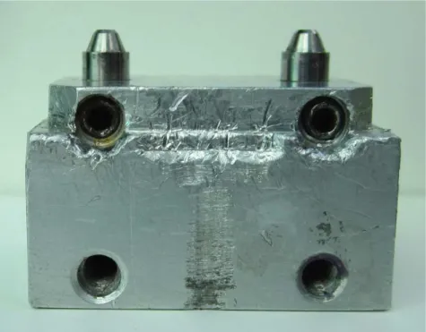
A aluminum block presenting 20 mm (width) x 20 mm (height) x 30 mm (length), two holes 20 mm apart from each other, containing two multiunit 4.1 titanium analogs (Neodent SA Curitiba, Parana, Brazil) inserted into parallel to each other, secured by screws. The stopper block has a lateral and circling the two mm receded, which acts as stop device for tray. (Figure 1)
Fabrication and preparation of Custom Trays
Tray polyether adhesive (3M ESPE, Seefeld, Germany) was applied thinly and evenly
over the inner surface of each tray and extended approximately 3 mm into the outer surface of
the tray, along the periphery. The adhesive was allowed to dry for 15 minutes before the
impressions were made.
Experimental desing
The control group was the aluminium block. Other six groups were performed according
the impression thecnique and die material (GC Fujirock EP, GC Europe, Leuven, Belgium and
Zero Stone, Dentona AG, Europe, Dortmund, Germany). (Figure 2)
Soft viscous polyether (Impregum Penta Soft; 3M ESPE, Seefeld, Germany) was the
impression material chosen for all transfer procedures. 4,17 Automatic mixing and dispenser Pentamix 2 (3M ESPE, Seefeld, Germany) was used to standardize all mixtures. Polyether was injected around the transfer copings and placed inside the custom tray using the dispenser. The
tray was seated on the aluminum block with gentle pressure until the lateral and circling stops contacted the base of the aluminum block. The impression material was allowed to set for 12 minutes from the start of mixing; the manufacturer’s setting time was doubled to compensate a
delayed polymerization reaction at room temperature rather than a mouth temperature. A
standardized load of 1.25 kg was exerted over each tray during the impression procedures. 18,19 This was enough to force the excess material to flow out and to maintain constant pressure
throughout the working time.
Splinting of Transfer Copings
Groups 2a e 2b: Squared impression copings (Figure 3). The squared impression copings were adapted to the abutment analogs on the aluminum block using 10 Ncm of torque.
Groups 3a e 3b: Splinted squared copings using dental floss and acrylic resin – Pattern (GC
abutment analogs on the aluminum block using 10 Ncm of torque. Dental floss was adaptaded to the squared impression copings, and the acrylic resin inserted around until polymerization.
Groups 4a e 4b: Splinted squared copings using dental floss and bis-acrylic resin Protemp 4 (3M ESPE, Seefeld, Germany) (Figure 5).
Specimen Preparation
After the polymerization of the impression material, the impression copings were unscrewed and the tray was separated from the aluminum block. The minipilar abutment analogs (Neodent SA Curitiba, Parana , Brazil) were fited to the impression copings using 10 Ncm of torque while the copings were held with a hemostatic forceps to prevent the squared coping from rotating inside the impression. 20 This procedure is not necessary for the modified squared technique, but it was performed in order to standardize the methodology.
The impressions were poured with a die stone - Type IV dental stone, GC Fujirock EP and Zero Stone, 30 minutes after the impressions were made. A ratio of 20 mL of distilled water to 100 g of stone was used, and the stone was mixed manually for 15 seconds to incorporate the water
and then mechanically mixed under vacuum for 45 seconds with a digital vacuum spatulator
(Turbomix EDG Equipment, São Carlos, SP, Brazil). All mixes were vibrated into the
impression. The stone casts were allowed to set two hours before separation from the
impressions.
Measurement
After 7 days, the distances between the analogs of each specimen were mesured. Ten
The measurement was analyzed using software (AxionVision 4.8.1, Zeiss; Carl Zeiss,
Jena, Germany) that received the images from a camera (AxionCam ICc3, Zeiss; Carl Zeiss,
Jena, Germany) coupled to a stereomicroscope (Zeiss Discovery V20; Carl Zeiss, Jena,
Germany), observed at 10X magnification.
Statistical analysis
Data showed normal distribution of values. Shapiro-Wilk test was performed using using SPSS/PC Statics 18 (SPSS Inc., Chicago, IL, USA) at level significance of 5%.
For the quantitative variable, parametric test (Test t) was used to compare the mean values of the aluminum block (Group 1) to the mean values of each group.
Two way ANOVA was done to evaluate the relationship between die and impression techniques and Post hoc analysis with Tukey.
RESULTS
Sample included 30 specimens (n =5) and one control Group - aluminum block. Table 1 shows the mean, standard deviations, minimum value, maximum value of the distance between analogs for the different groups.
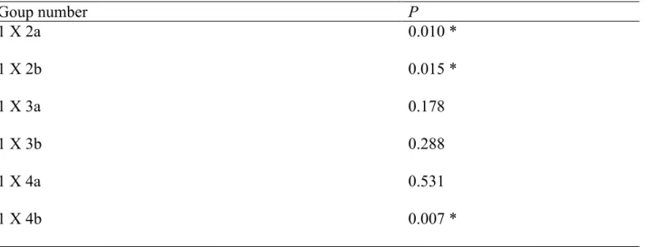
The parametric test (Test t) was used to compare the mean values of aluminum block Group 1 to the mean values of each group. Statistical significant differences for groups 2a (P= .001), 2b (P=.015) and 4b (P=.007) were found, as shown on Table 2.
It was observed one difference statistically significance between the die (P=.03) (Table 3) and were not observed differences statistically significance among impression techniques (P=.05) (Table 4) and interaction between die and impression techniques (P=.10).
DISCUSSION
The null hypothesis of the present study, stating that the accuracy of casts would not be affected by the impression technique and trademark of stone was rejected. Significant differences were detected between the control group and squared impression copings technique pouring with differences’ stones and between splinted squared copings using dental floss and bisacrilica resin poured with a die stone Zero Stone.
An ideal impression technique would involve minimal time; be easy to use, inexpensive, and comfortable for the patient; and, would give the most accurate results. The implant definitive casts with CAD/CAM technology (Robocasts) from coded healing abutment impressions represents a simpler and innovative alternative to conventional implant impression techniques, but more studies are necessary. Al-Abdullah et al, 2013 21, evaluate the accuracy of the Robocasts and compare them to those definitive casts fabricated with conventional implant impression techniques (open tray with splinted impression copings technique). The implant definitive casts fabricated from the coded healing abutment impressions seems to to be less accurate comparing to those fabricated from the open tray, with conventional implant impression techniques.
The splinted squared copings minimized the chance of accidental displacement of the
who produced more accurate working casts with splinted self- curing acrylic resin technique. Another aspect that must be considered when the modified squared technique is used is that extra time is involved in creating the modified squared coping. It seems to be a clinical advantage using splinting impression copings with light-polymerized composite resin to minimize problems related to resin polymerization contraction and to avoid this time-consuming multiple-step procedure (time required for acrylic resin polymerization and the additional step of sectioning and rejoining the acrylic resin splint). Therefore, it improved efficiency, reduction of visit time and greater transfer precision as a result of splinting stability. 24
Wise in 2001 25, evaluated the fit of fixed prostheses fabricated on master casts poured in a conventional die stone and in an ultra-low-expansion plaster was investigated in vitro. An impression was made of patient replicas with inter-implant abutment distances of 50 and 35 mm. In this in vitro study, master casts poured in an ultra-low-expansion plaster limited to a maximum abutment dimension of 35 mm were more accurate than casts with 50-mm inter-abutment spans or those poured in a conventional die stone. 25
For practical clinical purposes, an understanding of the magnitude and variability of distortion when employing certain methods and materials helps the clinician to determine witch procedures provide the best accuracy. The splinted squared copings using dental floss and acrylic resin poured with both die stone (GC Fujirock EP and stone Zero Stone) and Splinted squared copings using dental floss and bis-acrylic resin poured with die stone (GC Fujirock EP) showed
more similar distance between the analogs as the Control Group. These results suggests that more accurate casts could produce a higher percentage of the time using the direct technique
CONCLUSIONS
Under the limitations of this study, the splinted squared copings using dental floss and acrylic resin and splinted squared copings using dental floss and bis-acrylic resin (Protemp 4- 3M ESPE) poured with a die stone GC Fujirock EP produced cast most similar to the control Group.
REFERENCES
1. Zarb GA, Schmitt A. The longitudinal clinical effectiveness of osseointegrated dental implants: the Toronto study. Part III: Problems and complications encountered. J Prosthet Dent. 1990 Aug;64(2):185-94.
2. Sahin S, Cehreli MC. The significance of passive framework fit in implant prosthodontics: current status. Implant Dent. 2001;10(2):85-92.
3. Lee H, So JS, Hochstedler JL, Ercoli C. The accuracy of implant impressions: a systematic review. J Prosthet Dent. 2008 Oct;100(4):285-91.
4. Naconecy MM, Teixeira ER, Shinkai RS, Frasca LC, Cervieri A. Evaluation of the accuracy of 3 transfer techniques for implant-supported prostheses with multiple abutments. Int J Oral Maxillofac Implants. 2004 Mar-Apr;19(2):192-8.
5. Del'Acqua MA, Chavez AM, Compagnoni MA, Molo Fde A, Jr. Accuracy of impression techniques for an implant-supported prosthesis. Int J Oral Maxillofac Implants. 2010 Jul-Aug;25(4):715-21.
6. Papaspyridakos P, Benic GI, Hogsett VL, White GS, Lal K, Gallucci GO. Accuracy of implant casts generated with splinted and non-splinted impression techniques for edentulous patients: an optical scanning study. Clin Oral Implants Res. 2011 Jun 2.
7. Faria JC, Silva-Concilio LR, Neves AC, Miranda ME, Teixeira ML. Evaluation of the accuracy of different transfer impression techniques for multiple implants. Braz Oral Res. 2011 Apr;25(2):163-7.
8. Hariharan R, Shankar C, Rajan M, Baig MR, Azhagarasan NS. Evaluation of accuracy of multiple dental implant impressions using various splinting materials. Int J Oral Maxillofac Implants. 2010 Jan-Feb;25(1):38-44.
9. Carr AB. Comparison of impression techniques for a five-implant mandibular model. Int J Oral Maxillofac Implants. 1991 Winter;6(4):448-55.
10. Humphries RM, Yaman P, Bloem TJ. The accuracy of implant master casts constructed from transfer impressions. Int J Oral Maxillofac Implants. 1990 Winter;5(4):331-6.
11. Choi JH, Lim YJ, Yim SH, Kim CW. Evaluation of the accuracy of implant-level impression techniques for internal-connection implant prostheses in parallel and divergent models. Int J Oral Maxillofac Implants. 2007 Sep-Oct;22(5):761-8.
12. Vigolo P, Majzoub Z, Cordioli G. Evaluation of the accuracy of three techniques used for multiple implant abutment impressions. J Prosthet Dent. 2003 Feb;89(2):186-92.
13. Del Acqua MA, Chavez AM, Castanharo SM, Compagnoni MA, Mollo Fde A, Jr. The effect of splint material rigidity in implant impression techniques. Int J Oral Maxillofac Implants. 2010 Nov-Dec;25(6):1153-8.
14. Assif D, Marshak B, Schmidt A. Accuracy of implant impression techniques. Int J Oral Maxillofac Implants. 1996 Mar-Apr;11(2):216-22.
15. Inturregui JA, Aquilino SA, Ryther JS, Lund PS. Evaluation of three impression techniques for osseointegrated oral implants. J Prosthet Dent. 1993 May;69(5):503-9.
16. Schwedhelm ER, Lepe X. Fracture strength of type IV and type V die stone as a function of time. J Prosthet Dent. 1997 Dec;78(6):554-9.
18. Assuncao WG, Filho HG, Zaniquelli O. Evaluation of transfer impressions for osseointegrated implants at various angulations. Implant Dent. 2004 Dec;13(4):358-66.
19. Del'Acqua MA, Arioli-Filho JN, Compagnoni MA, Mollo Fde A, Jr. Accuracy of impression and pouring techniques for an implant-supported prosthesis. Int J Oral Maxillofac Implants. 2008 Mar-Apr;23(2):226-36.
20. Del'Acqua MA, Chavez AM, Amaral AL, Compagnoni MA, Mollo Fde A, Jr. Comparison of impression techniques and materials for an implant-supported prosthesis. Int J Oral Maxillofac Implants. 2010 Jul-Aug;25(4):771-6.
21. Al-Abdullah K, Zandparsa R, Finkelman M, Hirayama H. An in vitro comparison of the accuracy of implant impressions with coded healing abutments and different implant angulations. J Prosthet Dent. 2013 Aug;110(2):90-100.
22. Lee HJ, Lim YJ, Kim CW, Choi JH, Kim MJ. Accuracy of a proposed implant impression technique using abutments and metal framework. J Adv Prosthodont. 2010 Mar;2(1):25-31.
23. Assuncao WG, Britto RC, Ricardo Barao VA, Delben JA, dos Santos PH. Evaluation of impression accuracy for implant at various angulations. Implant Dent. 2010 Apr;19(2):167-74. 24. Rutkunas V, Ignatovic J. A technique to splint and verify the accuracy of implant impression copings with light-polymerizing acrylic resin. J Prosthet Dent. 2014 Mar;111(3):254-6.
Anexos
Fig. 1. Aluminium Block.
Fig. 2. Squared impression copings.
Table I. Mean values, standard deviations, minimum value, maximum value of analogs distance
Table II. P-values for comparison between control Group and the others, using Test t
Goup number P
1 X 2a 0.010 *
1 X 2b 0.015 *
1 X 3a 0.178
1 X 3b 0.288
1 X 4a 0.531
1 X 4b 0.007 *
* significant differences Goup
number Mean (mm)
Standard deviation
Minimum value (mm)
Maximum value (mm)
Test t
1 15.19 .017 15.17 15.21 A
2a 15.30 .055 15.24 15.38 B
2b 15.34 .085 15.26 15.46 C
3a 15.25 .093 15.11 15.35 AD
3b 15.10 .156 14.86 15.26 AE
4a 15.29 .332 15.02 15.87 AF
Table III. Comparison between die.
Material n Mean (mm) Standard error
of mean
Tukey test
Die Fuji Rock 15 15.28 .042 A
Die Zero Stone 15 15.15 .042 B
Table IV. Comparison between impression techniques.
Techniques n Mean (mm) Standard error
of mean
Tukey test
Square impression copings 10 15.320 .052 A Splinted square copings with
dental floss and acrylic resin
10 15.181 .052 A
Splinted square copings with dental floss and bis-acrylica resin
DISCUSSÃO GERAL
Os modelos de trabalho reproduzem a posição intraoral dos implantes em torno dos tecidos duros e moles buscando sempre a maior precisão possível, para permitir o assentamento passivo das próteses sobre ele fabricadas e, consequentemente eliminando a tensão sobre os componentes de suporte e ao redor do osso (20).
O assentamento passivo é um dos pré-requisitos mais importantes na reabilitação oral sobre implantes e na manutenção da osseointegração. O assentantamento passivo ocorre quando todas as superfícies, do implante e prótese são alinhadas sem aplicação de força. Diversos
O bloco de aluminio possuiu como valores médios de gap entre os analogos e a infraestrutura valores de 60 µm (implante 65°) e 30 µm (implante inclinado a 90 graus). Valores estes aceitaveis na literatura como a assentamento passivo ideal. O maior valor encontrado neste estudo foi de 510 µm (Técnica de moldagem de arrasto sem união dos components e implante inclinado a 65 graus), sendo este último considerado como valor inaceitável de assentamento passivo.
Diferentes técnicas de moldagem buscam reproduzir a posição intraoral dos implantes. A não observância de consenso sobre as técnicas de moldagens faz que a pesquisa continue sempre se aperfeiçoando. O surgimento de novos materiais e técnicas implicam no surgimento de novas pesquisas laboratoriais e clinicas.
A literature cientifica apresenta duas técnicas de moldagem, que são as técnicas de transferência (transfer) e a de arrasto ou sacar (pick up).
Na técnica de transferência (casquete cônico) utiliza-se moldeiras fechadas, transferentes cônicos que possibilitam a sua permanencia na cavidade bucal após a remoção do molde, esta apresenta uma menor precisão (25-27).
defendem a união para minimizar a possibilidade de girar os componentes no interior do molde, quando se parafusa a replica ou analogo.
Ainda ao compararmos separadamente os valores de gap entre os analogos (A e B) e infraestrutura, obtivemos maiores valores para o implante B (inclinado) no grupo Técnica de moldagem de arrasto sem união dos componentes (510 µm). Valores estes de acordo com trabalhos de Carr et al (1991) (27) e Akalin et al. 2013 (30) na qual concluiram que a desadaptação parece estar relacionada com a ausencia de paralelismo entre os implantes.
Outra etapa para a confecção das próteses implanto suportadas é a obtenção dos modelos. O material mais comumente utilizado para modelos e troqueis é o gesso odontológico.
Segundo McCartney e Pearson, (1994) (31) e Del ́Acqua et al., (2008) (32), a expansão do gesso durante a presa também pode causar desadaptação. No início da cristalização, ocorre ligeira expansão de 0,1% a 0,05%. Mesmo para o poliéter que possui uma boa rigidez, essa expansão de cristalização do gesso pode gerar falha. No artigo 2 tivemos como uma das variaveis diferentes marcas comercias de gesso tipo IV, sendo elas o GC Fujirock EP (GC Europa, Leuven, Belgica) e Zero Stone (Dentona AG, Europa, Dortmund, Alemanha). O gesso Zero Stone segundo fabricante possui zero de expansão, assim tentou-se verificar se hipotese de que os modelos de gesso confeccionados com este material seriam mais precisos que os confecionados com outra marca de gesso. Os resultados mostraram diferenças significantes entre os gessos.
compardos com o bloco de alumínio (padrão).
Na moldagem de arrasto ou de sacar (pick up) pode-se realizar a união dos transferes quadrados com diferentes materiais. Na literatura encontramos os seguinte materiais: fio dental + resina acrílica R.A. (DuraLay, Reliance, Illinois, EUA), fio dental + RA (Pattern - GC Europe, Leuven, Belgica) (6), RA com extensão nas distais para retenção (7), RA com espera de 17 min, tempo de maior contração, secção e nova união (8), resina acrilica de dupla polimerização (AccuSet -EDS,. Hackensack, NJ) –Assif et al 1999 (9), RA fotopolimerizada (lâminas de resina acrilica) (10), barras pré polimerizadas (RA ou resina composta) (10), resina polimerizada por luz, fios de ortodontia + RA, silicona de condensação, gesso tipo I para moldagem (11), jateamento dos tranferentes e aplicação do adesivo do poliéter (7). A resina acrílica autopolimerizavel é um dos materiais com ótimos resultados mais utilizado nestes estudos (6, 7, 12, 13, 33). Uma das desvantagens apresentadas deste material é a alta contração de polimerização. Outro aspecto que deve ser considerado quando a técnica de arrasto é utilizada é o tempo extra envolvido na união dos transferentes quadrado. Parece haver uma vantagem clínica na união com resina polimerizada por luz por esta minimizar problemas relacionados com a contração da polimerização da resina e pela diminuição do tempo consumido nesta etapa (tempo requerido para a polimerização da resina). As resinas bisacrilicas são materiais desenvolvidos para minimizar os efeitos negativos da resina acrílica, além de ser mais fácil de usar, devido possuir um cartucho automisturador, na qual já nos dá as proporções corretas, possui menor contração de polimerização e maior resistência.
acordo com Lee et al , 2010 (18) , Naconecy et al, 2004(29) , Assunção et al , 2010(34) , que produziram modelos de trabalho mais precisos quando unidos com resina acrilica autopolimerizavel.
CONCLUSÕES
A partir dos resultados do presente estudo pode-se concluir que:
1. Os modelos de gesso obtidos a partir da técnica de arrasto sem união dos componentes apresentaram maiores discrepâncias do que aqueles obtidos a partir da técnica de sacar com união dos componentes com resina acrílica, quando utilizados implantes inclinados.
2. Os implantes angulados (65°) mostraram maiores valores de gap que implantes os perpendicular a superfície.
3. Os modelos de gesso obtidos a partir das técnicas de arrasto sem união, com união em Resina Acrílica e com união em resina bisacrílica não mostraram diferenças estatisticamente significantes.