Real-Time Simulation and Analysis of the Induction
Machine Performances Operating at Flux Constant
Aziz Derouich
Department of Electrical and Computer Engineering The Higher School of Technology Sidi Mohamed
Ben Abdellah University Fez, Morocco
Ahmed Lagrioui
Department of Electrical and Computer Engineering The Higher National School of Arts and Trades
Moulay Ismail University Meknes, Morocco
Abstract—In this paper, we are interested, in a first time, at the study and the implementation of a V/f control for induction machine in real time. After, We are attached to a comparison of the results by simulation and experiment for, speed responses, flux and currents of the real machine, with a DSPACE card and model established by classical identification (Direct Current test , blocked-rotor test, no-load test , synchronous test), to ensure the validity of the established model. The scalar controlled induction motor allows operation of the motor with the maximum torque by simultaneous action on the frequency and amplitude of the stator voltage, with conservation of the ratio V/f.
Speed reference imposes a frequency at the inverter supplying the voltages needed to power the motor, which determines the speed of rotation. The maximum torque of the machine is proportional to the square of the supply voltage and inversely proportional to the frequency voltage. So, Keep V/f constant implies a operating with maximum constant torque. The results obtained for the rotor flux and the stator currents are especially satisfactory steady.
Keywords—Induction Machine Modeling; Scalar-controlled induction machine; Experimental identification; Environment Matlab/Simulink/DSPACE
I. INTRODUCTION
The speed control of electrical machine aims to control the operating point of the group "Engine - Load" to best meet the needs of a given industrial application.
This multidisciplinary field currently experiencing considerable importance in industry and in research and requires varied skills in the field of electrical engineering.
Recent progress in the areas of power electronics, automation and digital control led to the development of control system of high performance [1...7].
Today, alternating current machines can replace the direct current machine in most variable speed applications. In particular, induction motor is considered the preferred actuator in constant speed applications. It offers some advantages compared to the DC motor, such as its ease of manufacture and maintenance, without brush-collector device, its weight and low inertia, with an excellent performance. It is also appreciated for its reliability and robustness. However, the simplicity of its mechanical structure is accompanied by a high complexity in the mathematical model (multi-variable and non-linear).
Indeed, in the induction motor, the stator current is used both to generate the flux and the torque. The natural decoupling of the DC machine no longer exists.
On the other hand, we can’t know the internal variables of the rotor (rotor current for example) only through the stator. The difficulty is that it exists a complex coupling between the input variables, output variables and the internal variables of the machine, such as torque and speed.
The technological advances had allowed to solve this problem and to develop appropriate strategies of the engine command.
Among them, we can mention the scalar control, Field-oriented control (FOC), direct torque control (DTC), direct mean torque control (DMTC), vector torque control (VTC) and direct self-control (DSC) [8].
The control of AC machine is now almost exclusively based on digital techniques, and so many control algorithms are implemented by the major powers of calculations available. These control algorithms require knowledge of the mathematical model of the machine. The elements constituting of the latter are determined using a set of tests on the machine, especially the Direct Current test, the no-load test, the blocked-rotor test (slip = 1) and the synchronization test (slip = 0). The resulting model is widely used in the stationary regime, that is to say, the machine is assumed to operate at steady regime and powered by a three phase system of constant effective value and rotates at constant speed.
This model is no longer valid if the machine is powered by a three-phase inverter controlled using a control algorithm. This led us to check the validity of this model by comparing the responses in speed, currents and flux of the induction motor obtained by simulation in the Simulink environment with those obtained in real time experimentation.
The scalar control is the easiest control of speed of the induction motor; it allows varying the speed of the machine over a wide range. This is one of the first commands, developed for the variable-speed driving. In this command, we focus on the amplitude of the controlled variable and not to its phase [9]. There are two variants of the scalar control:
Direct scalar control where the magnetic flux is controlled from its estimate or its measurement
The second method is more difficult to put into practice. So, we focus in this article on the first approach because it's simple and most used.
II. MODELING THE INDUCTION MOTOR
A good closed-loop control must be based on a mathematical model of the process to be controlled or enslaved. In our application, we use a model of the asynchronous machine that describes the dynamic behavior of the various parameters involved in the control system.
The machine considered in this paper, is a three-phase squirrel-cage (short circuit rotor) asynchronous machine. So, her electrical equations are writing in the following form:
In the stator : (1)
In the rotor : (2)
With:
Vsa, Vsb, Vsc the Three stator voltages. Isa, Isb, Isc : the Three stator currents. Vra, Vrb, Vrc the Three rotor voltages. Ira, Irb, Irc : the Three rotor currents.
Φsa, Φsb, Φsc : the flux through the three phases of the
stator.
Φra, Φrb, Φrc : the flux through the three phases of the
rotor.
To replace these differential equations at coefficients which depend on time by simple differential equations with constant coefficients, we apply the Park transformation theory that is the important approach of modeling of induction
machine and it’s the most used [10].
In our case, we focus on the modeling of induction machine in a reference frame linked to the rotating field. The equations of the machine are then as follows:
Voltages at the stator : (3)
Voltages at the rotor (shorted): (4)
Flux at the stator with Msr = Mrs = M : (5)
Flux at the rotor rotor with Mrs = Msr = M : (6)
Electromagnetic torque: (7)
With: (d, q) : rotating frame
Isd, Isq : the stator currents in the d-q plane
Vsd, Vsq : The stator voltages in the d-q plane
Ird, Irq : The rotor currents in the d-q plane
Φsd, Φsq : The stator flux in d-q plane
Φrd, Φrq : The rotor flux in d-q plane
Rs, Rr : Stator and rotor resistances
Ls, Lr : Stator and rotor Inductances
M : Mutual inductance
s : The stator pulsation
: The mechanical pulsation
sl : The slip pulsation
J : Moment of inertia f : Friction coefficient Tr: Load torque
Te: Electromagnetic torque
Ω: Mechanical speed ( = p. )
III. PRINCIPLE OF SCALAR CONTROL
Several scalar controls exist depending on whether it operates on the current or the voltage. They mainly depend on the topology of the actuator used (Udc voltage or Idc current). For our application, we used a voltage inverter supplying the induction machine and drived by the scalar control (ratio V/f constant). The speed variation is achieved by variation of the stator pulsation that is generated directly by the speed controller. This method of control is based on the model of the machine in the stationary regime. For this reason, the study of the machine's model is important in this regime.
The principle of this control is to maintain constant of the ratio V/f, which means keeping the torque constant.
Indeed, if the value of the resistance of the stator windings is neglected, and it is often the case, the electromagnetic torque-slip characteristic in the stationary regime takes the following form:
(8)
: Equivalent resistance rotor conductors reduced to the stator.
p: Number of pole pairs. : Stator pulsation. Vs: Stator voltage.
L: Leakage inductance converted to the primary side.
Often, we are interested in the maximum value of the torque. To calculate it, we look for the value of s that maximizes the expression of the electromagnetic torque Te and then implant it in the previous expression. We give in the equation below the result only:
(9)
We deduce that the maximum torque is proportional to the square of the report:
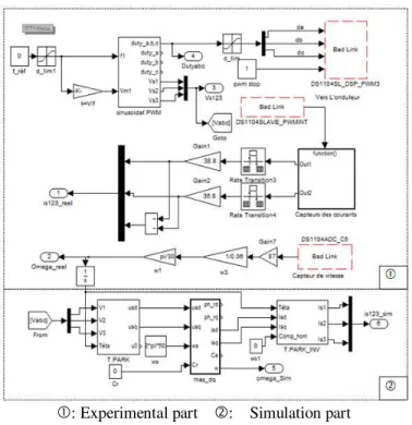
The command structure allowing the realization of the control at V/f constant of the induction machine is illustrated in the following scheme of Simulink:
: Experimental part : Simulation part Fig. 1. Simulation scheme
Part represents the control law allowing issuing the command signals of the switches (IGBT) of the inverter and the output variables, i.e. the stator currents and rotation speed.
Part represents the model of the induction machine in the plane (d-q) with parameters that we want to evaluate, i.e. the stator currents, the rotor flux and the speed of rotation.
IV. PARAMETERS MACHINE
The induction motor parameters which we have realized our experimentation are shown in the table below:
TABLE I. PARAMETRS MACHINE
Parameter Value
Rated power 3 KW
Supply voltage 220V/380V
Synchronous speed 1500 rpm à 50 Hz
Rated speed 1400 rpm
Rated currents (Υ/Δ) 7.2A/12.5A
Stator resistance Rs 0.55
Rotor resistance Rr 0.62
Pair pole number 2
longitudinal inductance Ld 0.0997 H
Transversal Inductance Lq 0.093 H
Mutual Inductance M 0.093 H
Moment of inertia J 0.01469 kg.m2
Viscous friction coefficient f 0.003035 Nm.sec/Rad
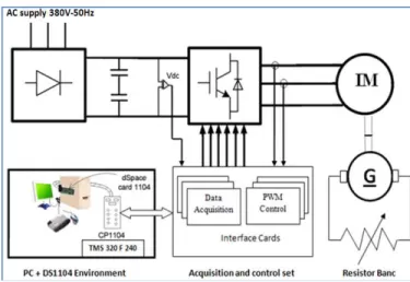
V. BANC TEST
The experimental banc Test is consisted of the following elements:
- A cage induction motor having the following characteristics: 3KW, 4 poles, 7.2A/12.5A, 220V/380V, 50Hz, 1400 rpm.
- A diode rectifier providing the DC voltage to the inverter.
- A voltage inverter consists of three bridges, at IGBT and diodes. Three bridges aim to attack the machine and a fourth arm can also be used, when coupled to a resistive load and a suitable command, to protect the electronics of power during braking phases because the diode rectifier is not reversible current and may cause an increase in voltage across the DC bus during braking phases.
- Sensors currents and speed:
Two current probes LEM HX15-P, LEM P-LV25 for measuring stator currents.
A tachogenerator 10B0 for measuring the speed. - The DSPACE-TMS320F240 DSP card ensures the
software and digital command aspects. In particular, the digital acquisition of the input signals, the transmission of the inverter bridge control (output signals), current and speed control of the machine. - The programs, developed under Simulink environment,
are implemented within the card. The interface with the operator is then provided by the CONTROL DESK GUI software.
- The DESK CONTROL software is a graphical interface allowing viewing all available variables on
patterns Simulink/Dspace. CONTROL DESK
The figure 2 below shows the block diagram of the experimental banc.
Fig. 2. Block diagram of the experimental banc
The image below shows the real banc experimental [11]:
Fig. 3. Experimental banc
VI. COMPARISON OF EXPERIMENTAL RESULTS VERSUS THOSE OBTAINED BY SIMULATION
A. Rotation speed
Response speed is given by the figure 4 below:
Fig. 4. Rotation speed of the machine
1) The real speed of the machine.
2) Speed of the simulated model.
We find that:
The response time of the simulated model is equal to 0.14s
The response time of the real system is equal to 0.28s.
The simulated model, as regards the speed, doesn’t perfectly follows the machine at the time of starting because all the elements of the machine are still be cold.
B. The stator currents
The stator current of the first phase is shown in the figure below:
Fig. 5. The stator currents
1) The real stator current of phase 1 of the machine
2) The stator current of phase 1 of the simulated model.
The figure 6 below shows the various stator currents
Fig. 6. Stator currents
We note that the current of the simulated model follows perfectly the real current in the stationary regime. It's not the same case in the transient regime.
C. Rotor flux
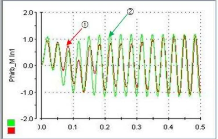
Fig. 7. The rotor flux in phase 1 of the machine
1) The real rotor flux of phase 1 of the machine.
2) The rotor flux of phase 1 of the simulated model.
The shapes of the rotor flux in phase 2 of the machine are shown in Figure 7 below.
Fig. 8. The rotor flux in phase 2 of the machine
We note, in the figure 7 and the figure 8 above, that the rotor flux of the induction machine in real time and the rotor flux of the equivalent model in the plane of Park converge perfectly in the stationary regime.
VII. CONCLUSION
In this article, we had presented the scalar command of the induction machine operating as a motor. The implementation of the control algorithm explained the performance and limitations of the model of Park established from the values of the parameters of the asynchronous machine obtained by experimental identification (direct current Test, no load, locked-rotor and in synchronism). Indeed, we have seen, from the results, that the model of Park presents some identification errors but which are acceptable and especially in the stationary regime. The errors noticed in the transient regime are mainly due to the moment of inertia of the load on the motor shaft which we have not taken into account.
So an adaptive command that takes into account the parametric variations of the machine (especially the moment of inertia and the load torque) can easily overcome these errors. The perspective of this work consists to implement other algorithms of the induction machine control and compare the result of simulation with the real time.
ACKNOWLEDGMENT
The authors are grateful to the anonymous referees for their valuable comments and suggestions to improve the presentation of this paper. They wish to express their special thanks to all the participants of this work.
REFERENCES
[1] M. Daijyo, I. Hosono, H. Yamada, and Y. Tunehiro, “A method of improving performance characteristics of general purpose inverter,” Trans.Inst. Elect. Eng. Jpn., vol. 109-D, no. 5, pp. 339–346, May 1989 [2] L. Ben-Brahim, “Improvement of the stability of the V/f controlled
induction motor drive systems,” in Proc. IIEEE ECON’98, 1998, pp.859–864.
[3] Jaume D, “Commande des systèmes dynamiques par calculateur”, Eyrolles, 91.
[4] Hisham A, Kandil, “La commande optimale des systèmes dynamiques”, Lavoisier, 04.
[5] Pandya, S.N.; Chatterjee, J.K., ”Power Electronics, Drives and Energy Systems (PEDES) & 2010 Power India, 2010- Issue - 20-23 Dec. 2010 pages 1-7.
[6] H.Mahmoudi, A.Lagrioui “Flux-weakening control of permanent magnet synchronous machines”, Journal of Theoretical and Applied Information Technology, 31st December 2011. Vol. 34 No.2 - pp: 110-117.
[7] A.Abbou, H.Mahmoudi, A.Lagrioui, “Comparison of the Rotor Flux Oriented and Direct Torque Flux Control Methods for Induction Motors used in Electric Vehicles”, STA'2006 - Topic ACS "Analysis and automatic Control of Systems ", pp: 1-11.
[8] S ALLIRANI, V JAGANNATHAN, “Direct torque control technique in induction motor drives - a review”, Journal of Theoretical and Applied Information Technology, 28th February 2014. Vol. 60 No.3 – pp: 452-475
[9] R. Toufouti, ”Contribution à la commande directe du couple de la machine asynchrone”, Thèse de Doctorat, Faculté des Sciences de l’Ingénieur, Université Mentouri Constantine, Algérie, 2008.
[10] Sudhir Kumar, P. K. Ghosh, S. Mukherjee ”A Generalized Two Axes Modeling, Order Reduction and Numerical Analysis of Squirrel Cage Induction Machine for Stability Studies”, International Journal of Advanced Computer Science and Applications, Vol. 1, No. 5, November 2010, pp: 63-68.
[11] A. ABBOU, T. NASSER, H. MAHMOUDI, M. AKHERRAZ, A. ESSADKI, ”Induction Motor controls and Implementation using dSPACE”,WSEAS TRANSACTIONS on SYSTEMS and CONTROL, Issue 1, Volume 7, January 2012, pages 26-35.
AUTHORS PROFILE
Mr. Aziz Derouich obtained his diploma from the Superior School of Technical Teaching of Rabat 1995. Further, he got his Diploma of Superior Studies (DESA) in Electronics, Automatic and Information Processing in 2004 and the Ph.D. degree in computer engineering in 2011 from the "University Sidi Mohamed Ben Abdellah" of Fez. He was a professor of Electricity and Computer Science in "Lycée Technique, El Jadida" from 1995 to 1999 and in "Lycée Technique, Fez" from 1999 to 2011.
include static converters, electrical machines control, renewable energy and E-learning.
Mr. Ahmed Lagrioui obtained his diploma from the Superior School of Technical Teaching of Rabat 1996. Further, he got his Diploma of Superior Studies (DESA) in 2006 and the Ph.D. degree in electrical engineering in 2011 from Mohammadia School’s of engineers, Rabat, Morocco.
He was a professor of Electricity and Computer Science in "Lycée Technique, Taza" from 1996 to 2001 and in "Lycée Technique, Fez" from 2003 to 2014.
Since 2014, he is a Professor at the Higher National School of Arts and Trades, Moulay Ismail University, Meknes, Morocco.