Gravitational Search Technique for Optimum
Design of Reinforced Concrete T-Beams
Puneet Mittal
M.Tech Research Scholar, Department of Civil Engineering, DAVIET, Jalandhar, India
Sonia Chutani
Assistant Professor, Department of Civil Engineering, DAVIET, Jalandhar, India
Jagbir Singh
Associate Professor, Department of Civil Engineering, GNDEC, Ludhiana, India
Abstract: - This study proposes an iterative cost optimization methodology for reinforced concrete T-beams under flexural and shear effects. In this research work the principle design objective is to minimize the total cost of beam after full filling all the requirements according to IS 456:2000 and in other case of ductile detailing, additional requirements according to IS 13920:1993 are used. To optimize, the overall cost of beam is used as objective function and the codal requirements are used as design constraints. Gravitational search (GSA) algorithm is employed for the optimization process and combined with the reinforced concrete design according to IS 456:2000 - plain and reinforced concrete - code of practice. Some design examples of RC T-beams and their parametric sensitivity have also been studied.
Keywords: Cost Optimization; T-Beams; Reinforced Concrete; Gravitational search; code requirements.
I. INTRODUCTION
Optimization is a process in which an objective function is maximized or minimized. In engineering design, especially in civil engineering, the security measures and cost must be taken into account together. Thus, the optimization is one of the vital issues in civil engineering. In several studies, the optimum cost design of the reinforced concrete (RC) elements has been investigated. Coello et.al.optimized RC beams [1] using a search technique employing genetic algorithm (GA). Also, genetic algorithm was employed to find the optimum design of reinforced concrete biaxial columns [2]. The shape optimization of RC flexural members by using GA to optimize the diameter and number of main reinforcement bars was studied by Rath et.al [3]. GA was used in order to find the optimum cost of RC flexural frames [4]. Ferreira et.al. studied on the optimal design of T-shaped RC beams according to various design codes [5]. The simulated annealing algorithm was also employed to find optimum values of continuous steel reinforced beams [6]. Cost optimization of singly and doubly RC beams was investigated by Barros et.al. [7].Govindaraj and Ramasamy studied on the detailed optimum design of RC continuous beams using GA. Different groups of reinforcements were considered to find the solution with the optimum cost [8]. Also, Govindaraj and Ramasamy studied on the optimization of RC frames using GA [9]. The optimum height and area of the reinforcement bars was investigated for RC beams by Barros et. al. [10].In this study, T-shaped RC beam elements under flexural and shear effect were optimized for the best cost. Genetic algorithm (GA) was employed for the optimization process. Optimum design of the beam height and percentage of reinforcement steel both at compressive and tensile sections were searched according to the modified methodology of GSA for RC design procedure according to IS 456:2000 - plain and reinforced concrete - code of practice. [11].In the present study, optimum design of reinforced concrete T-beam as per IS 456:2000 has been attempted using GSA.
II. OVERVIEW OF OPTIMIZATION TECHNIQUE
masses guarantees the exploitation step of the algorithm and corresponds to good solutions. The masses are actually obeying the law of gravity as shown in Equation (1) and the law of motion in Equation (2).
F = G (M1M2 / R2) (1)
(2)
Based on Equation (1), F represents the magnitude of the gravitational force, G is gravitational constant, M1 and M2
are the mass of the first and second objects and R is the distance between the two objects. Equation (1) shows that in the Newton law of gravity, the gravitational force between two objects is directly proportional to the product of their masses and inversely proportional to the square of the distance between the objects. While for Equation (2), Newton’s second law shows that when a force, F, is applied to an object, its acceleration, a, depends on the force and its mass M.
In GSA, the agent has four parameters which are position, inertial mass, active gravitational mass, and passive gravitational mass [12]. The position of the mass represents the solution of the problem, where the gravitational and inertial masses are determined using a fitness function. The algorithm is navigated by adjusting the gravitational and inertia masses, whereas each mass presents a solution. Masses are attracted by the heaviest mass. Hence, the heaviest mass presents an optimum solution in the search space. The steps of GSA are as follows:
Step 1: Agents initialization
The positions of the N number of agents are initialized randomly.
Xi = ( xi1,…xid, …, xin), for i= 1,2,..,N. (3)
xid represents the positions of the ith agent in the dth dimension, while n is the space dimension. Step 2: Fitness evolution and best fitness computation
For minimization or maximization problems, the fitness evolution is performed by evaluating the best and worst fitness for all agents at each iteration.
Minimization problems:
best(t) = min fitj(t) j İ{1,…,N} (4)
worst(t) = max fitj(t) j İ{1,…,N} (5)
Maximization problems:
best(t) = max fitj(t) j İ{1,…,N} (6)
worst(t) = min fitj(t) j İ{1,…,N} (7)
fitj (t) represents the fitness value of the jth agent at iteration t, best(t) and worst(t) represents the best and worst
fitness at iteration t.
Step 3: Gravitational constant (G) computation: Gravitational constant G is computed at iteration t.
G(t) = G0e(-Įt/T) (8)
G0and Į are initialized at the beginning and will be reduced with time to control the search accuracy. T is the total
number of iterations.
Step 4: Masses of the agents’ calculation:
Gravitational and inertia masses for each agent are calculated at iteration t.
Mi(t) = (10)
Mi(t) = (11)
Mai and Mpi are the active and passive gravitational masses respectively, while Mii is the inertia mass of the ith agent.
Step 5: Accelerations of agents’ calculation:
Acceleration of the ith agents at iteration t is computed.
aid(t) = Fid(t) / Mii(t) (12)
Fid(t) is the total force acting on ith agent calculated as:
Fid(t) = (13)
j İ KBEST, ji
Kbest is the set of first K agents with the best fitness value and biggest mass. Kbest will decrease linearly with time and at the end there will be only one agent applying force to the others.
Fijd(t) is computed as the following equation:
Fijd(t) = G(t).(Mpi(t) x Maj(t) / Rij(t) + İ) .(xjd(t) - xid(t)) (14)
Fijd(t) is the force acting on agent i from agent j at dth dimension and tth iteration. Rij(t) is the Euclidian distance
between two agents i and j at iteration t. G(t) is the computed gravitational constant at the same iteration while İis a small constant.
Step 6: Velocity and positions of agents:
Velocity and the position of the agents at next iteration (t+1) are computed based on the following equations:
vid(t+1) = randi x vid(t) + aid(t) (15)
xid(t+1) = xid(t) + vid(t+1) (16)
Step 7: Repeat steps 2 to 6
Figure 1 Flow chart of GSA
III. PROBLEM FORMULATION
The optimization techniques in general enable designers to find the best design for the structure under consideration. In this particular case, the principal design objective is to minimize the total cost of structure, after full filling all the requirements according to IS456: 2000, and additional requirements according to IS13920: 1993 in other case. The resulting structure, should not only be marked with a low price but also comply with all strength and serviceability requirements for a given level of applied load. The reinforced cement concrete flanged reinforced beam subjected to dead load as well as an imposed load is taken in this present research work, the cost optimization and comparison between [Ref 8] design is made for the structural element. All the design variables are taken as continuous variables.
Objective function
The objective function is the total cost consisting of individual cost components due to concrete, steel and formwork. The cost of any component is inclusive of material, fabrication, and labour. The objective function is expressed mathematically as
, and are the unit cost of concrete, steel and formwork respectively. , and are the volume of concrete, weight of longitudinal plus transverse steel and area of formwork respectively.
Constant parameters
The parameters to be specified prior to the solution of the optimization problem are the structural geometry, loading conditions, material properties, support conditions, width of support, unit cost of different components, reinforcement bar spacing and cover details. However the value of dead load which includes the self-weight of the beam is automatically updated based on the cross-sectional dimensions.
Design variables
The cross-sectional dimensions of the beam are considered as design variables. It is a general practice to provide same width of beams in all spans. In this study design variables are depth of the beam and the percentage of steel provided in the beam according to Indian Standard Code. It is also assumed that same width of support is provided. Constraints
Constraints to be imposed are taken based on strength, serviceability, ductility and other side constraints. The constraints regarding bar spacing and other bar detailing requirements are considered in the optimum detailing stage itself. All the constraints are represented in the normalized form for the modeling.
Flexural constraints
condition. The stress–strain profiles for both concrete and steel is adopted as per IS code provisions. The neutral axis depth can be limited in order to ensure desired level of ductility.
While calculating the required area of steel, minimum area of steel to be provided is taken into account to ensure availability of minimum flexural strength at all sections. As per IS code, the calculated area of bottom steel in each span is modified such that 1/3rd and 1/4th of bottom steel areas at mid span is available at the discontinuous and continuous ends of that beam.
Shear constraints
The minimum area of shear reinforcement, maximum and minimum spacing of stirrups are taken into account. However, the nominal shear stress in concrete is limited to the maximum shear stress to avoid failure of concrete in shear compression prior to yielding of stirrups.
Deflection constraints
The serviceability requirements for deflections are imposed in many codes of practice in the form of effective span to effective depth ratios. According to IS 456:2000, maximum allowable span to effective depth ratio for simply supported beam is 20, if span is less than 10 m.
IV. SOLUTION OF OPTIMIZATION PROBLEM
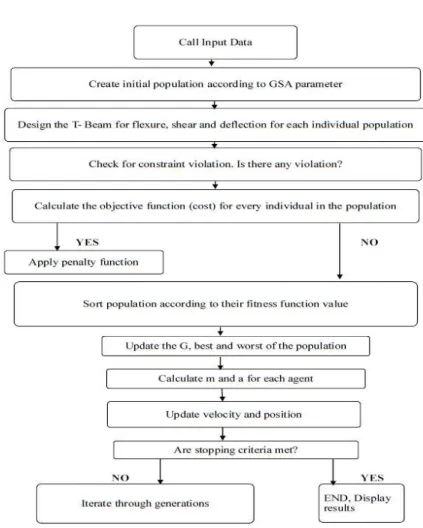
Figure 2 Flow chart representing Design of T-Beam with Gravitational search algorithm
Some simply supported beam examples are presented [Table 1] to demonstrate the effectiveness and efficiency of designing RC beams using GSA. The fixed parameters for all design examples are fck = 25 MPa, fy = 400 MPa, minimum percentage of tensile reinforcement = (1.4/fy), fixed width of beam = 240 mm, maximum sectional depth to width ratio = 2, clear cover to main reinforcement = 70 mm, thick of flange (slab) = 120 mm, width of support = 280 mm, limiting neutral axis factor (xu/d) = 0.4 as given in Ref. [8]. The mid-span section experiencing sagging moment is designed as a T-section with breadth of flange taken equal to 1500 mm. It is assumed that 50% of mid-span steel is continued into the supports and the mid mid-span bottom steel is curtailed at a distance of 0.1 l from the centre of support. The present optimum results are compared with ref [8] for a simply supported T- beam taken from Ref [8] [Table2]. The relative cost of concrete, steel and form work are taken as 1/m3, 0.01515/kg and 0.42/m2 respectively as given in Ref. [8]. The depth of beam section and percentage of steel are considered as variable. The optimum design is governed by the deflection limit state. The cost components are given in Table 1.
The above design examples are solved on on Pentium(R) Dual-Core CPU T4400 @ 2.20GHz and 2.00 GB RAM.
The time taken to optimize a T beam is 6 seconds.
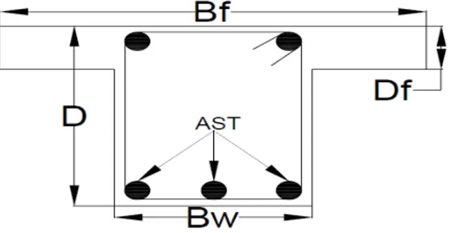
Figure 3 Section of Reinforced Concrete T-Beam
Table1. Design Examples of Reinforced Concrete T-Beams
Fixed parameters- > Df = 120 mm, Bw =240 mm, C_Cov = 70 mm, Bf = 1500 mm
Input parameters Design parameters
Example Span(m) Dead load (KN/m) Live Load (KN/m) Fy (N/mm2)
Fck
(N/mm2) Depth(mm)
Steel % Optimum Cost Conventi onal Cost
1 3 16 15 415 20 338 1.5 1.3646 1.3878
2 4 22 20 500 25 313 2.11 2.0696 2.1213
3 5 25 20 415 20 361 2.13 2.7109 2.9580
4 6 12 10 500 25 322 2.01 3.3315 3.4287
5 4 18 14 415 20 303 2.06 1.9913 2.0232
Table2. Comparison of cost components of present study with existing study
Study Method Quantity Cost of components Total
cost
Reduction in cost
Concrete (m3)
Formwork (m2)
Steel (kg)
Concrete Form work
Steel
Ref [8] GA 0.224 2.829 46.251 0.224 1.188 0.701 2.1131
V. PARAMETRIC STUDY
The effect of some design parameters on optimum cost of T-beam has been studied in this section. The optimum cost of T-beam has been computed for example 1 with varying loads, span, grade of steel, grade of concrete, thickness of flange and concrete clear cover and variations of optimum cost are represented in following figures. It has been seen from the figure 3 and figure 4 that cost of beam increases with increase of load and span. The optimum cost decreases for higher grades of steel and concrete as shown in figure 5 and figure 6. The cost of beam is optimized when thickness of flange is kept between 160 mm and 180 mm and clear cover of concrete is kept between 30 mm to 35 mm for other fixed design parameters of example1[figure 7 and figure 8].
Figure 3 Cost Vs Load Figure 4 Cost Vs Span
Figure7 Cost Vs thickness of flange Df Figure 8 Cost Vs clear cover
VI. CONCLUSIONS
x A design methodology as per IS 456-2000 for optimizing reinforced concrete T-beam is presented which utilized physical phenomenon of gravitational search. Gravitational search algorithm has very few parameters and less time consuming as compared to genetic algorithm.
x A significant saving has been found while designing beam using gravitational search algorithm. A saving of 4% has been observed as compared to optimum design of T beam done by genetic algorithm.
x Optimum results are sensitive to thickness of flange and clear cover to concrete.
x There is significant decrease in cost for higher grades of steel and concrete.
x The different trends are observed for varying design parameters which supply the engineers more applicable designs.
REFERENCES
[1] C. C. Coello, F. S. Hernandez, F. A. Farrera, Optimal Design of Reinforced Concrete Beams Using Genetic Algorithms, Expert Systems with Applications, Vol. 12, 1997, pp. 101-108.
[2] M. Y. Rafiq, C. Southcombe, Genetic algorithms in optimal design and detailing of reinforced concrete biaxial columns supported by a declarative approach for capacity checking, Computers and Structures, Vol. 69, 1998, pp. 443-457.
[3] D. P. Rath, A. S. Ahlawat, A. Ramaswamy, Shape Optimization of RC Flexural Members, Journal of Structural Engineering, Vol. 125, 1999, pp-1439-1446.
[4] C. V. Camp, S. Pezeshk, H. Hansson, H., Flexural Design of Reinforced Concrete Frames Using a Genetic Algorithm, Journal of Structural Engineering, Vol. 129, 2003, pp- 105-11.
[5] C. C. Ferreira, M. H. F. M. Barros, A. F. M. Barros, Optimal design of reinforced concrete T-sections in bending, Engineering Structures, Vol. 25, 2003, pp. 951-964.
[6] M. Leps, M. Sejnoha, New approach to optimization of reinforced concrete beams, Computers and Structures, Vol.81, 2003, pp- 1957– 1966.
[7] M. H. F. M. Barros, R. A. F. Martins, A. F. M. Barros, Cost optimization of singly and doubly reinforced concrete beams with EC2-2001, Structural and Multidisciplinary Optimization, Vol. 30, 2005, pp-236–242.
[8] V. Govindaraj, J. V. Ramasamy, Optimum detailed design of reinforced concrete continuous beams using Genetic Algorithms, Computers and Structures, Vol. 84, 2005, pp- 34–48.
[9] V. Govindaraj, J. V. Ramasamy, Optimum detailed design of reinforced concrete frames using genetic algorithms, Engineering Optimization, Vol. 39 No.4, 2007, pp- 471– 494.
[10] A. F. M. Barros, M. H. F. M. Barros, C. C. Ferreira, Optimal design of rectangular RC sections for ultimate bending strength, Structural and Multidisciplinary Optimization, Vol. 45, 2012, pp-845–860.
[11] IS 456:2000 - PLAIN AND REINFORCED CONCRETE - CODE OF PRACTICE.