Dynamic response of low frequency Profiled Steel Sheet Dry
Board with Concrete infill (PSSDBC) floor system under human
walking load
Abstract
This paper investigates the dynamic response of a composite structural system known as Profiled Steel Sheet Dry Board with Concrete infill (PSSDBC) to evaluate its vibration ser-viceability under human walking load. For this point, thir-teen (13) PSSDBC panels in the category of Low Frequency Floor (LFF) were developed using Finite Element Method (FEM). The natural frequencies and mode shapes of the studied panels were determined based on the developed finite element models. For more realistic evaluation on dynamic response of the panels, dynamic load models representing human walking load were considered based on their Funda-mental Natural Frequency (FNF), and also time and space descriptions. The peak accelerations of the panels were de-termined and compared to the limiting value proposed by the standard code ISO 2631-2. Effects of changing thickness of the Profiled Steel Sheet (PSS), Dry Board (DB), screw spacing, grade of concrete, damping ratio, type of support, and floor span on the dynamic responses of the PSSDBC panels were assessed. Results demonstrated that although some factors reduced dynamic response of the PSSDBC sys-tem under human walking load, low frequency PSSDBC floor system could reach high vibration levels resulting in lack of comfortableness for users.
Keywords
structural composite floor system, profiled steel sheet dry board, vibration serviceability, human walking load, dy-namic response, human comfort.
Farhad Abbas Gandomkar∗,
Wan Hamidon Wan Badaruz-zaman and Siti Aminah Osman
Department of Civil & Structural Engineering, Universiti Kebangsaan Malaysia, Bangi, Selan-gor – Malaysia
Received 10 May 2011; In revised form 03 Jan 2012
∗Author email:
1 INTRODUCTION
limited to SPAN/360 (A58, 1982) or between SPAN/180 and SPAN/480 in different specifi-cations (ACI 318-77, 1977 and AISC, 1978), and second is the minimum of DEPTH/SPAN for flexural members depending on the end restrains (ACI 318-77, 1977) [14]. Ellingwood and Tallin [14] stated that control of the static deflection is not sufficient to evaluate the vibration serviceability of floors.
On the other hand, Al-Foqaha et al. [2] reported a number of researchers (Onysko 1970, 1985, 1988; Polensek 1970, 1971, 1975, 1988; Polensek et al. 1976; Allen 1974, 1990; Allen and Rainer 1976; Allen and Murray 1993; Murray 1979; Chui 1986; Smith and Chui 1988; Ebrahimpour and Sack 1989; Ohlsson 1988, 1991; Kalkert et al. 1993; Dolan et al. 1995, Lenzen 1966; Wiss and Parmelee 1974, Filiatrault et al. 1990; Foschi et al. 1995; Kalkert et al. 1995) have declared that evaluation of the floor vibration serviceability may not be performed by control of the static deflection such as SPAN/360 [2]. Wood floor systems were studied based on the finite element method under dynamic loads induced by human activities. A series of design curves related to Root-Mean-Square (RMS) acceleration, mass, and FNF were proposed and compared with the experimental study which concluded in a close agreement. It was demonstrated that the vibration criteria based on static properties or FNF are not enough to prevent unwanted vibration of floors [2].
The International Standards Organization (ISO 2631-2) [22] recommended an acceleration limit as a baseline in terms of RMS for various applications of floors, as illustrated in Fig. 1. This Standard proposed a criterion on the basis of the peak acceleration by multiplication of baseline with 10 for offices, 30 for shopping malls and indoor footbridges, and 100 for outdoor footbridges.
The American Institute of Steel and Construction (AISC) [26] has proposed criteria for human comfort which are the same as the ISO Standard [22], as shown in Fig. 1.
Various authors have evaluated the vibration serviceability of floors under human activities through determination of their dynamic responses, analysis, and experiment from few years ago [24]. Sandun de Silva and Thambiratnam [10], da Silve et al. [8], da Silve et al. [9], El-Dardiry and Ji [13], Williams and Waldron [37], Chen [6] determined dynamic responses of composite floors under human activities to assess their vibration serviceability. Ellingwood and Tallin [14] mathematically studied the dynamic response of floors under a pragmatic model instead of the pedestrian dynamic load. Experimental serviceability criteria were also reported to minimise the vibration of the floors. Smith and Chui [31] presented a usable method for designers based on a flow chart to evaluate the dynamic response of lightweight wood-joist floor by determination of natural frequency and RMS acceleration of the system under the heel-drop impact load. Howard and Hansen [21] studied the vibration analysis of waffle floors based on a mathematical method for several manufacturing buildings which was also verified by finite element and experimental results. Foschi et al. [16] carried out an experimental and analytical study on the vibration response of wood floors as a lightweight panel useful in residential and commercial buildings under impact load induced by users. Occupants were modelled by two simple oscillators, one degree of freedom and two degrees of freedom. Osborne and Ellis [28] presented a study on a long-span lightweight LFF (FNF lower than 10 Hz [25]) system by the analysis of various methods to evaluate the vibration acceptability of the system through obtaining FNF, damping ratio, and acceleration. Willford et al. [36] reviewed five methods to predict the response of structures under the footfall load. The study was performed in two parts; floor and bridge with the FNF lower than 10 Hz, and also floor with the FNF above 10 Hz (HFF). Mello et al. [24] also studied dynamic analysis of a composite system made of concrete slab and steel beams. The research on acceptability of studied models was conducted under four types of dynamic loads which were represented by human walking load, measurement of peak acceleration of panels, and comparison with limit of codes. The dynamic response of the mentioned floors was investigated by using FEM as a modern computational tool for structural analysis.
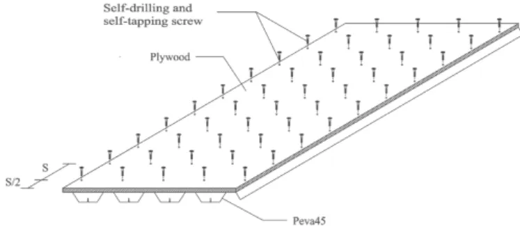
The PSSDB is a lightweight composite structural system consisting of the PSS and DB attached together by self-drilling and self-sapping screws, as shown in Fig. 2.
Study on using concrete as an infill material in the PSSDB system uncovered the perfor-mance of concrete on increasing the stiffness of the system [34]. The perforperfor-mance of using concrete in trough of the PSS of the PSSDB system was revealed experimentally to reduce its response where the panel is applied under human walking load [17].
It was reported that since the PSSDB system is slender and flexible in its nature, the natural frequency of the floor system may be low and becomes perceivable to users [39]. In addition, Gandomkar et al. [18] showed experimentally and numerically that in practical dimensions of floors, the FNF of the PSSDBC system is lower than the PSSDB system and is in the category of LFF. Therefore, the PSSDBC floor panels with usual spans are exposed to vibrations of human activities, because the FNF of a LFF is close to frequency range of human activities. Accordingly, a consistent dynamic analysis of the PSSDBC system with the practical span is advisable to evaluate the vibration serviceability of the system under human walking activities.
This paper deals with the dynamic response of the low frequency PSSDBC floor system used as offices and residences under human walking load. Thirteen PSSDBC panels were considered to reveal effects of different parameters such as boundary conditions, damping ratio, thicknesses of the PSS and DB, screw spacing, grade of concrete, and floor span on the dynamic response of the system. Firstly, natural frequencies and vibration modes of all panels were obtained. Secondly, dynamic responses of the studied panels were determined in terms of peak acceleration and also compared to limiting values proposed by the ISO 2631-2 [22] to show their vibration acceptability.
2 HUMAN-INDUCED DYNAMIC LOADS
In the current study, dynamic responses of the studied panels were determined under following four dynamic human walking loads [24] to evaluate their vibration acceptability.
2.1 First load model
First load model which represents people walking is shown in Eq. (1).
F(t) =P αicos(2πifs t) (1)
Where:
P: individual’s weight, taken as 700-800 N;
αi: dynamic coefficient for the ith harmonic force component;
i: harmonic multiple of the step frequency;
fs: step frequency;
t: time in seconds.
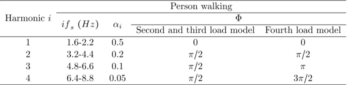
In the first load model, only one resonant harmonic of the load was considered. The harmonic multiple of the step frequency was adopted from Tab. 1 which depends on the FNF of the panel. For example, if calculated FNF of a panel is equal to 7.326 Hz (Panel Number (PN) of 9 = PN9), according to Tab. 1, only fourth harmonic of the walking loads with step frequency offs=1.8315 Hz (4×1.8315 Hz = 7.326 Hz) should be used in Eq. (1) to determine the first applied load on the panel. Fig. 3 illustrates the first dynamic load model for the panel with FNF equal to 7.326 Hz.
Table 1 Loading frequencies, dynamic coefficients, and harmonic phase angles.
Harmonici
Person walking
ifs (Hz) αi
Φ
Second and third load model Fourth load model
1 1.6-2.2 0.5 0 0
2 3.2-4.4 0.2 π/2 π/2
3 4.8-6.6 0.1 π/2 π
4 6.4-8.8 0.05 π/2 3π/2
2.2 Second load model
The second load model that represents human walking load is presented in Eq. (2).
F(t) =P[1+ ∑αicos(2πifs t+Φi)] (2)
Where:
P: person’ weight;
αi: dynamic coefficient for the harmonic force;
i: harmonic multiple (i=1, 2, 3, . . . , n);
fs: activity step frequency (dancing, jumping, aerobics or walking);
t: time;
Φi: harmonic phase angle.
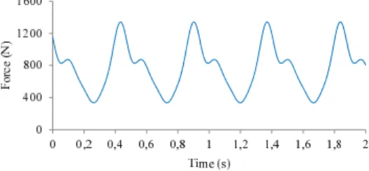
Unlike the previous load model, this load was composed of a static parcel and a combination of four time-dependent repeated loads presented by Fourier series. Four harmonics (see Tab. 1) were adopted to produce the second dynamic load model. Considering a panel the same as the discussed panel in the previous load model with the FNF equal to 7.326 Hz, the fourth harmonic with a step frequency of 1.8315 Hz (4×1.8315 Hz = 7.326 Hz) was the walking load resonant harmonic. Tab. 1 shows the dynamic coefficients and phase angles for each harmonic which were used to produce second dynamic load model, as depicted in Fig. 4.
Figure 4 Second and third load models for PN9.
2.3 Third load model
The mathematical function of the third load model which represents the human walking load is similar to the second one, presented in Eq. (2). Similar to the previous load model, the fourth harmonic with a step frequency of 1.8315 Hz was the resonant harmonic of human walking load (see Tab. 1). The third load model is more pragmatic than the last two kinds of the load models, as the position of this load is changed across the singular location of the floor system (see Fig. 5).
Figure 5 Person walking on the PSSDBC floor panel.
of the dynamic load with floor was calculated from the step distance and step frequency (see Tab. 2).
In this load model, the subsequent scheme was followed: In a panel identical to the panel in the previous load models, and according to Tab. 1, the step frequency was equal to 1.8315 Hz when the fourth harmonic was as the resonant harmonic. Therefore, in accordance with Tab. 2, the step distance was equal to 0.666 m (see Fig. 5).
Table 2 Person walking characteristics [24].
Activity Velocity Step distance Step frequency
(m/s) (m) (Hz)
Slow walking 1.1 0.6 1.7
Normal walking 1.5 0.75 2.0
Fast walking 2.2 1.0 2.3
The step period which corresponds with the step distance of 0.666 m is equal to 1/f = 1/1.8315 = 0.546 s (see Tab. 2). As it is shown in Fig. 5, four forces were considered representing one human step, which each of the forces as P1, P2, P3, and P4 was applied on the floor during 0.546(contact time)/3 = 0.18 s. The dynamic forces of P1, P2, P3, and P4 were not applied together at the same time. First, the load of P1 was applied on the floor according to Eq. (2) for 0.18s. At the end of this time period, the load of P1 became zero and the load of P2 was applied for 0.18 s. The other loads of the first person step, P3 and P4, were applied in the same procedure described previously. After 0.546 s, the first person step finished and the second person step started and the load of P1 of the second step was equal to the load of P4 in the first step. According to the mentioned method, the process continued repeatedly until all the dynamic forces applied along the considered path (see Fig. 12) of the floor.
2.4 Fourth load model
loads was consideration of the human heel effect in the fourth load which was ignored in the third load model. The human heel effect was uncovered to be an effective parameter on the increase of the load by comparing the third and fourth load models. According to Mello et al. [24], Varelo (2004) proposed the mathematical functions of the fourth load model as Eqs. (3)-(6).
F(t) = ⎧⎪⎪⎪⎪ ⎪⎪⎪⎪⎪ ⎪⎪ ⎨⎪⎪⎪ ⎪⎪⎪⎪⎪ ⎪⎪⎪⎩
(fmiFm−P
0.04Tp ) t+P if 0≤t<0.04Tp
fmiFm[C1(t−0.04Tp)
0.02Tp +1] if 0.04Tp≤t<0.06Tp
Fm if 0.06Tp≤t<0.15Tp
P[1+ ∑nhi=1αisin(2πifs(t+0.1Tp)+Φi)] if 0.15Tp≤t<0.90Tp
10(P− C2).(Tt
P −1)+P if 0.90Tp≤t<Tp
(3)
Fm: maximum Fourier series value, given by Eq. (4);
fmi: heel-impact factor;
Tp: step period;
C1: coefficients given by Eq. (5); C2: coefficients given by Eq. (6).
Fm=P(1+ nh
∑
i=1
αi) (4)
C1= (
1
fmi − − 1) (5)
C2= {
P(1− α2), ifnh=3 P(1− α2+ α4), ifnh=4
(6)
Mello et al. [24] reported that Varela (2004) and Ohlsson (1982) declared the impact factor varies person-to-person. In this study, impact factor was adopted equal to 1.12 (fmi = 1.12 [24]). Fig. 6 shows the dynamic load model of a panel which presented in the previous load models with the FNF of 7.326 Hz based on Eqs. (3)-(6).
3 DAMPING
Damping of structures used in the dynamic analysis is the most difficult item to find. Damping is not an exclusive physical phenomenon in structures dissimilar to mass and stiffness charac-teristics of a structural system. Therefore, modelling of damping in structures is not accurate like mass and stiffness and its determination is entirely possible based on full-scale measure-ments [19, 23]. The damping ratios are usually measured from experience or adopted through suggested values by design guides and cannot be determined through analytical methods [25]. Sandun de Silva and Thambiratnam [10] had a wide discussion on damping ratios suggested by some authors such as Osborne and Ellis (1990), Wyatt (1989-SCI-076), Hewitt et al. (2004), Murray (2000), Elnimeiri and Lyengar (1989), Brownjohn (2001), and Sachse (2002) which were dependent on application of floors and kind of partitions built on them. Damping ratios of 1.6%, 3%, 6%, and 12% were used for a steel-deck composite floor system in their studies.
In order to obtain damping ratios for floors, applicable design guides present simple guid-ance which has been summarised in Tab. 3 [25]. It can be seen that the SCI-P076, SCI-P331, and the AISC [26] have almost the same values for damping, but according to Middleton and Brownjohn [25], the Canadian Standards Association (CSA) clearly presents overestimated damping.
Table 3 Proposed damping ratios by standards [25].
Name of Standard
Bare floors or very few non-structural components (%)
Non-structural elements, i.e. furniture, fixtures
and fittings and cantilever partitions (%)
Heavily partitioned floor
with full height partitions (%)
SCI P076 1.5 3 4.5
SCI P331 1.1 3 4.5
AISC∗ 2 3 5
CSA 3 6 12
∗for offices, residences and churches
A new edition of SCI-P354 [30] presents critical damping ratios for various floor types which are very similar to those of SCI-P075 and SCI-P331 but with small differences in content, as summarised in Tab. 4.
Usually damping of the completely bare floors is not used because the bare floors are mostly utilised during the construction time and would not be used after the floors are occupied. Therefore, damping of bare floors is useful to reveal their dynamic response and to evaluate their vibration acceptability before the building is equipped [30].
Table 4 Proposed damping ratios by SCI-P354 [30].
ζ (%) Floor finishes
0.5 For fully welded steel structures, e.g. staircases 1.1 For completely bare floors or floors where only a small
amount of furnishings are present
3.0 For fully fitted out and furnished floors in normal use 4.5 For a floor where the designer is confident that par-titions will be appropriately located to interrupt the relevant mode (s) of vibration (i.e. the partition lines are perpendicular to the main vibrating elements of the critical mode shape)
1.52%, 0.83%, and 2.54% were found for the first four vibration modes, respectively.
Osborne and Ellis (1990) stated that although damping in a floor system can be measured by simple heel impact tests, various limitations make mostly unknown an exact value for damping of a steel-deck composite floor. Similarly, according to Dolan et al. [11], Smith and Chui (1988) reported a wood floor as a component of sheathing and joist which were connected to each other by glue, had more different damping characteristics than the same floor where nails are used instead of glue. Therefore, used construction techniques and workmanship in a floor are effective on its damping ratio.
In this study and in accordance with the above mentioned literature, the damping ratios were adopted as 1.1%, 3%, and 4.5% for the studied panels in order to consider different situations of the floor during the lifetime of its service (see Tab. 4).
4 STRUCTURAL MODEL
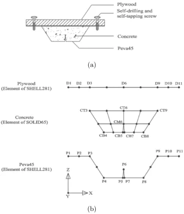
Peva45 is available in the local market by the width of 795 mm and maximum length of 15 m. Also, maximum length and width of plywood are 2400 mm and 1200 mm, respectively. Therefore, to prepare the PSSDB panels with practical dimensions with sizes greater than the size of Peva45 or plywood, some pieces of Peva45 and plywood should be used together. In the current study, the panels were consisted of four (4) pieces of Peva45 and eight (8) pieces of plywood. Also, C30 was used in trough of Peva45 as an infill material. Fig. 7 shows the section of the studied panels. The connection between the two adjacent Peva45 side by side panels (detail A) was represented by a typical lap joint idea as shown in Fig. 8. Wright and Evans [38] presented the connectivity characteristics of such joint. As can be seen in Fig. 8, nodes I(2) and J(2) are connected to nodes I(3) and J(3) respectively, assuming complete freedom in the longitudinal and rotational directions whilst assumed to have complete connection in the vertical and lateral directions [38].
Figure 7 The section of studied panels.
(a) (b)
Figure 8 Detail A: (a) Constructional model (b) Analytical model
as PSS, 18 mm thick plywood as DB, DS-FH 432 self-drilling and self-tapping screws at 200 mm screw spacing as the connectors, and C30 as an infill material in trough of Peva45. Thirteen (13) PSSDBC panels have been developed with various supports as shown in Fig. 9. The characteristics of these panels are summarised in Tab. 5.
Figure 9 Considered supports in the study.
The dynamic Young’s modulus of materials was used herein. According to the AISC [26], the dynamic Young’s modulus for steel can be chosen similar to its static value (BS 5950-Part4 [4]), i.e. 2.10×10⁵
Table 5 Characteristics of the studied panels.
Panel L Support Thickness Thickness Screw Grade of Damping
No. (mm) type (see of PSS of DB spacing concrete ratio (%)
(PN) Fig. 9) (mm) (mm) (mm)
1 4200 I 0.8 18 200 C30 1.1
2 4200 I 0.8 18 200 C30 3.0
3 4200 I 0.8 18 200 C30 4.5
4 4200 I 0.8 25 200 C30 1.1
5 4200 I 1.0 18 200 C30 1.1
6 4200 I 0.8 18 100 C30 1.1
7 4200 I 0.8 18 200 C35 1.1
8 4200 II 0.8 18 200 C30 1.1
9 4200 III 0.8 18 200 C30 1.1
10 4200 III 0.8 18 200 C30 3.0
11 4200 III 0.8 18 200 C30 4.5
12 3600 I 0.8 18 200 C30 1.1
13 4800 I 0.8 18 200 C30 1.1
be modelled as isotropic plates without any difficulties. Considering isotropic sheeting, the static Young’s modulus of plywood which is available in the local market adopted as 7164 MPa [40] in this study. However, the dynamic value was chosen 10% greater than the static value according to Bos and Bos Casagrande [3].
In accordance with BS 8110 [5], the static Young’s modulus of concrete was determined as 24597 MPa and 26567 MPa for concrete grades of 30 and 35, respectively. da Silva et al. [8] discussed that according to the AISC [26] in situations where the composite slab is subjected to dynamic excitations concrete becomes stiffer than the case when is subjected to pure static loads. This issue [26] suggests a 35% increase in the dynamic Young’s modulus of the conventional concrete in comparison with the static Young’s modulus. Therefore, dynamic modulus of elasticity as 33206 MPa and 35865 MPa were adopted for concrete grades of 30 and 35, respectively.
as 386 kN/mm and 417.60 kN/mm respectively for C30 and C35 where spacing between the springs was considered as 200 mm. The density of Peva45 and plywood was adopted as 7850 kg/m3
and 600 kg/m3
, respectively. Also, the density of concrete was determined as 2273 kg/m3
in the laboratory [18].
5 COMPUTATIONAL MODEL
The FEM presents a more accurate dynamic response especially for structures with involved geometry. Using this method is increased because it can reduce the cost of computing functions [25]. The logical estimation on vibration of composite floors under walking load is a complicated work because of complexity in geometry of structures, variety of material properties in different structural components, and the nature of walking load as a continuous and transient load. It has been known that using FEM can cover and solve the mentioned tasks foremost [6]. Therefore, the FEM was used in this study to evaluate the dynamic response of the PSSDBC panels under the dynamic human walking load.
Developed finite element models were simulated by the use of refined mesh in the ANSYS program [33]. In the studied system, the PSS and DB were made of SHELL281 element as a suitable element for analysing thin to moderately-thick shell structures. In addition, the self-drilling and self-tapping screws were represented by COMBIN14 element as connection between Peva45 and plywood and also between concrete and Peva45. Moreover, SOLID65 element was adopted for modelling of concrete in the computational models.
For more clarification, Fig. 10 shows the procedure of modelling Peva45, concrete, and plywood in the simulation for one bay of the studied system. The connection between elements of Peva45 and concrete [20], plywood and concrete, and also Peva45 and plywood in the simulation is performed by using spring element (COMBIN14) in three directions (X, Y, and Z). In this case and according to Fig. 10, nodes of D2 and D10 were respectively connected to nodes of P2 and P10 which stiffness of springs was adopted as 610 N/mm [27] in X and Y directions (see section 4) and 105
N/mm in Z (vertical) direction (see Fig. 10). Nodes of CT3, CB4, CB5, CB7, CB8, CT9, and D6 were connected to nodes of P3, P4, P5, P7, P8, P9, and CT6 respectively in the same procedure as mentioned above with 1 N/mm [20] stiffness of springs for all directions (X, Y, and Z). Node of CM6 was connected to node of P6 by 386 KN/mm stiffness of springs in X and Y directions (see section 5) and 106
N/mm in Z direction, when C30 is used in the PSSDBC system.
6 DYNAMIC ANALYSIS OF THE STUDIED PANELS
To determine the dynamic responses of the PSSDBC composite panels, a linear time-domain analysis was performed [7]. The dynamic responses of the studied panels were obtained from a vast parametric analysis performed using finite element ANSYS program [33]. The results were natural frequencies, displacements, velocities, and accelerations.
(a)
(b)
Figure 10 (a) One bay PSSDBC structural system (b) Situation of nodes in elements of one bay PSSDBC system.
under the four dynamic load models described previously. Then, the obtained accelerations were compared to the proposed peak acceleration limit by the ISO [22].
6.1 Natural frequencies and mode vibrations of studied panels
Gandomkar et al. [18] conducted a wide experimental and numerical investigation on the natural frequencies of the PSSDBC system. The numerical study performed by FEM presented accurate results compared to the corresponding experimental results. In the current study, developed finite element models which were verified in the literature [18] were used to obtain the natural frequencies of the studied panels, as tabulated in Tab. 6.
The results of Tab. 6 illustrate that increasing the thickness of plywood and Peva45 decreased and increased the FNF of the system, respectively. Therefore, it can be seen that the obtained results reveal the effect of the mass and stiffness of Peva45 and plywood on the FNF of the system.
It was also shown that the decrease of the screw spacing enhances the FNF of the panel, because the panel will be stiffer [35].
four-Table 6 First six natural frequencies of the studied panels.
Panel No. f01 (Hz) f02 (Hz) f03 (Hz) f04 (Hz) f05 (Hz) f06 (Hz)
(PN)
1, 2, 3 4.742 5.514 7.670 10.696 13.852 15.926
4 4.675 5.587 8.048 11.477 15.035 15.661
5 4.891 5.801 8.259 11.625 14.858 16.895
6 4.82 5.598 7.863 11.001 14.214 18.819
7 4.849 5.616 7.768 10.797 13.982 16.013
8 6.693 7.341 9.221 12.171 15.504 18.871
9, 10, 11 7.326 9.208 12.385 18.236 19.81 22.299
12 6.447 7.098 9.076 12.063 15.426 19.596
13 3.648 4.515 6.767 9.748 12.688 13.226
sided support instead of two-sided support (perpendicular to the strong direction of the PSS) can considerably increase the FNF of the system. It is clear that change in the panel span can also change the FNF of the panel. The FNF of the panels had two properties. First, all were smaller than 10 Hz; therefore, the category of the studied panels was LFF. Second, all were greater than 3 Hz, as a minimum limitation of FNF for floors proposed by the SCI – P354 [30]. First six vibration modes of the PN9 which were obtained by the finite element model are illustrated in Fig. 11.
6.2 Peak acceleration of studied panels
The peak accelerations of the panels were determined by the dynamic analysis of the developed finite element models. Person walking across the panel was considered in the third and fourth dynamic load models. Therefore, the paths of walking should be defined. The peak acceler-ations of all models were determined for path 1 (see Fig. 12) under three different support models (see Fig. 9). Also, the peak accelerations of PN2, PN7, and PN10 were obtained where person used path 2 (see Fig. 12) for walking. Tab. 7 indicates the peak accelerations of the PSSDBC panels under the four previously described loads. This table also presents the limit of peak acceleration recommended by the ISO 2631-2 [22] for residences and offices (see Fig. 1).
(a) Mode shape associated to the first natural frequency: f01=7.326 Hz
(b) Mode shape associated to the second natural frequency: f02=9.208 Hz
(c) Mode shape associated to the third natural frequency: f03=12.385 Hz
(d) Mode shape associated to the fourth natural frequency: f04=18.236 Hz
(e) Mode shape associated to the fifth natural frequency: f05=19.810 Hz
(f) Mode shape associated to the sixth natural frequency: f06=22.299 Hz
Figure 12 Layout of paths.
response of the panels increased. Mello et al. [24] also focused on this point and stated that this is a substantial increase in the structure. The peak acceleration of the panels under the fourth load model was assessed higher than those under the third load model. On the other hand, the scheme of loading on the panels in the third and fourth load models was the same as each other. Therefore, this increase should be caused by the heel impact factor (fmi=1.12) used in the fourth load model.
In accordance with the design criteria proposed by the ISO 2631-2 [22] and also based on the peak accelerations of the panels produced by the first load model, all the studied panels did not have any problems regarding the human comfort. By comparing the results of PN1, PN8, and PN9, an interaction was revealed between the dynamic load model with different parameters such as support conditions and dynamic characteristics of the panels which made an unknown phenomenon in the dynamic response of the panels. It should be noted that the harmonic of the resonant in PN1 was the third harmonic; therefore, the dynamic coefficient of the load is 0.1. However, the fourth harmonic is the resonant harmonic in PN8 and PN9, accordingly, the dynamic coefficient is 0.05. By investigation of the results of the second load model, all studied panels did not show any problems related to the human comfort. On the other hand, by comparing the peak accelerations of the dynamic analysis of the panels under the third and fourth load models and recommendations of the ISO 2631-2 [22], it was uncovered that all panels were not comfortable for human under these loads.
Table 7 Peak accelerations of the studied panels at resonance.
Panel Load Load Load model III Load model IV
ISO 2631-2 [22]
No. model I model II (m/s2
) (m/s2
)
(PN) (m/s2
) (m/s2
) Path 1 Path 2 Path 1 Path 2
1 0.03367 0.03917 0.10397 - 0.12594
-0.04903 (m/s2
)
2 0.02508 0.03161 0.09671 0.08946 0.11591 0.10261
3 0.01796 0.02679 0.08993 - 0.10862
-4 0.02691 0.03552 0.09948 - 0.11043
-5 0.02373 0.03284 0.09463 - 0.10884
-6 0.02828 0.03614 0.09957 - 0.12414
-7 0.03187 0.03833 0.10245 - 0.12219
-8 0.02939 0.04287 0.11907 0.10745 0.13006 0.11214
9 0.03439 0.04647 0.13851 - 0.15313
-10 0.02936 0.03785 0.11324 0.13061 0.14838 0.16353
11 0.02566 0.03021 0.10572 - 0.13264
-12 0.02439 0.03135 0.09184 - 0.10023
-13 0.03948 0.04886 0.14952 - 0.17823
-of I (see Tab. 5 and Fig. 9) and respectively 13.63% and 24.36% for that with the support type of III (see Tab. 5 and Fig. 9). By comparing PN1 with PN12 and PN13 it was shown that the length of the panels had a direct effect on the peak acceleration of the panels, where the response enhanced and reduced respectively for the increase and decrease of the length of panels for all four load models. However, these results are not addressable, as according to results of Ref. 24, the peak accelerations are not attributed to the length of the panels.
By comparing results of PN1 and PN8, it is obvious that control of sliding in support decreased the peak acceleration of the panel for the first load model. It may be due to the significant increase of the FNF of the panel, therefore, the dynamic coefficient changed from 0.1 to 0.05. On the other hand, as stated in the first load model only one harmonic considered depending on the FNF, the dynamic load applied on PN1 was higher than that on PN8. According to the results illustrated in Tab. 7, the mentioned issue was not shown to be effective when four harmonics considered in the dynamic load models (load models of II, III, and IV), even for PN9. The reason was about the complexity in the dynamic responses of the panels under interaction between supports and other substantial characteristics of structures.
7 FINAL REMARKS
This paper investigated the dynamic response of the PSSDBC low frequency floor panels under human walking load to evaluate the vibration serviceability of the system. Four dynamic load models were used while the third and fourth load models were more pragmatic having two properties; changing load according to the individual position, and generating time function corresponding to the nature of human walking load. The effect of human heel impact was also considered in the fourth load model.
The dynamic responses of the studied PSSDBC panels were obtained in terms of the peak acceleration and compared to the proposed limiting value by the ISO 2631-2 [22] where the panels used as residences and offices. The studied panels were showed to be comfortable when the first and second dynamic load models applied on them. The position of loads was changed across the individual directions when the third and fourth dynamic load models applied on the panels. For these two types of loads, two paths were selected to show the effect of direction of walking on the response of the panels. The peak accelerations of the studied panels under the third and fourth dynamic load models were determined higher than those of the first and second loads and also limiting value of the ISO 2631-2 [22]. Therefore, all panels were uncomfortable for users when the third and fourth load models applied on them. These results uncovered the fact that changing the position of the load is an effective item in the increase of the response of the panels.
Increasing the thickness of the PSS and DB and decreasing screw spacing significantly reduced the peak acceleration of the system. However, change of the concrete grade did not show a pronounced effect on changing the response of the PSSDBC system. Enhancement of the damping ratio of the PSSDBC system can considerably reduce the peak acceleration of the system. These results can be useful to help designers reduce the response of the floor by furniture and types of partitions (see Tab. 4).
The increase and decrease of the length of the studied panels enhanced and reduced the peak acceleration of the panels, respectively.
Acknowledgment Authors extremely appreciate the help of Mr. Alireza Bahrami, who con-tributed in some parts of this study.
References
[1] E. Ahmed. Behavior of profiled steel sheet dry board folded plate structures. PhD thesis, Department of Civil & Structural Engineering, Universiti Kebangsaan Malaysia, Malaysia, 1999.
[2] A. A. Al-Foqaha, F. C. William, and K. J. Fridly. Vibration design criterion for wood floors exposed to normal human activities. Journal of Structural Engineering, 125:1401–1406, 1999.
[3] F. Bos and S. Bos Casagrande. On-line non-destructive evaluation and control of wood-based panels by vibration analysis. Journal of Sound and Vibration, 268:403–412, 2003.
[4] BS 5950: Part4. Structural use of steelwork in building: Code of practice for design of composite slabs with profiled steel sheeting. British Standards Institution, UK, 1994.
[6] Y. Chen. Finite element analysis for walking vibration problems for composite building floor using ADINA: modeling, simulation, and comparison. Computer and Structures, 72:109–126, 1999.
[7] R. W. Clough and J. Penzien. Dynamic of structures. McGraw-Hill, Inc, New York, 2nd edition, 1993.
[8] J. G. S. da Silva, P. C. G. da S. Vellasco, S. A. L. de Andrade, F. J. da C.P. Soeiro, and R. N. Werneck. An evaluation of the dynamical performance of composite slabs.Computers and Structures, 81:1905–1913, 2003.
[9] J. G. S. da Silva, P. C. G. da S. Vellasco, S. A. L. de Andrade, and L. R. O. de Lima. Dynamic response of composite steel deck floors.Latin American Journal of Solids and Structures, 3:163–178, 2006.
[10] S. Sandun De Silva and D. P. Thambiratnam. Dynamic characteristics of steel-deck composite floors under human-induced loads. Computers and Structures, 87:1067–1076, 2009.
[11] J. D. Dolan, T. M. Murray, J. R. Johnson, D. Runte, and B. C. Shue. Preventing annoying wood floor vibrations. Journal of Structural Engineering, 125:19–24, 1999.
[12] A. Ebrahimpour, A. Hamam, R. L. Sack, and W. N. Patten. Measuring and modeling dynamic loads imposed by moving crowds.Journal of Structural Engineering, 122:1468–1474, 1996.
[13] E. El-Dardiry and T. Ji. Modeling of the dynamic behaviour of profiled composite floors. Engineering Structures, 28:567–79, 2005.
[14] B. Ellingwood and A. Tallin. Structural serviceability floor vibrations. Journal of Structural Engineering, 110:401– 420, 1984.
[15] B. Folz and R. O. Foschi. Coupled vibrational response of floor systems with occupants. Journal of Engineering Mechanics, 117:872–892, 1991.
[16] R. O. Foschi, G. A. Neumann, F. Yao, and B. Folz. Floor vibration due to occupants and reliability-based design guidelines. Canadian Journal of Civil Engineering, 22:471–479, 1995.
[17] F. A. Gandomkar and W. H. Wan Badaruzzaman. An experimental investigation on the effect of concrete infill on the dynamic behavior of profiled steel sheet dry board (PSSDB) system. InProceeding of CECAR 5 & ASEC Conference, (USB-paper no.160), Sydney, Australia, 2010.
[18] F. A. Gandomkar, W. H. Wan Badaruzzaman, and S. A. Osman. The natural frequencies of composite Profiled Steel Sheet Dry Board with Concrete infill (PSSDBC) system. Latin American Journal of Solids and Structures, 8:351–372, 2011.
[19] M. J. Glanville, K. C. S. Kwok, and R. O. Denoon. Full-scale damping measurements of structures in australia. Journal of Wind engineering, and Industrial Aerodynamics, 59:349–364, 1996.
[20] M. S. Harsoyo. Performance improvement of profiled steel sheeting dry board floor system by concrete infill. PhD thesis, Department of Civil & Structural Engineering, Universiti Kebangsaan Malaysia, Malaysia, 2004.
[21] C. Q. Howard and C. H. Hansen. Vibration analysis of waffle floors. Computers and Structures, 81:15–26, 2003.
[22] International Standards Organization / ISO 2631-2. Evaluation of human exposure to whole-body vibration. Part 2: Continuous and shock-induced vibration in buildings (1-80 Hz), 1989.
[23] A. Kareem and K. Gurley. Damping in structures: its evaluation and treatment of uncertainly. Journal of Wind engineering, and Industrial Aerodynamics, 59:131–157, 1996.
[24] A. V. A. Mello, J. G. S. da Silva, P. C. G. da S. Vellasco, S. A. L. de Andrade, and L. R. O. de Lima. Dynamic analysis of composite systems made of concrete slabs and steel beams. Journal of Constructional Steel Research, 64:1142–1151, 2008.
[25] C. J. Middleton and J. W. W. Brownjohn. Response of high frequency floors: A literature review. Engineering Structures, 32(2):337–352, 2010.
[26] M. M. Murray, D. E. Allen, and E. E. Ungar. Floor vibration due to human activity. In11th
Steel Design Guide Series: American Institute of Steel Construction, Chicago, USA, 1997.
[27] N. Nordin, W. H. Wan Badaruzzaman, and H. Awang. Connector stiffness of ‘Peva-Cemboard’ screwed connection in profiled steel sheet dry board (PSSDB) panel. InFifth International Conference on Construction in 21st
[28] K. P. Osborne and B. R. Ellis. Vibration design and testing of a long-span lightweight floor.The Structural Engineer, 68:181–186, 1990.
[29] V. Racic, A. Pavic, and J. M. W. Brownjohn. Experimental identification and analytical modeling of human walking forces: Literature review. Journal of Sound and Vibration, 326:1–49, 2009.
[30] A. L. Smith, S. J. Hicks, and P. J. Devine. Design of floors for vibration: A new approach. The Steel Construction Institute (SCI –P354), Silwood Park, Ascot, Berkshire SL5 7QN, 2007.
[31] I. Smith and Y. H. Chui. Design of lightweight wooden floors to avoid human discomfort.Canadian journal of Civil Engineering, 15:254–262, 1988.
[32] J. J. Stalnaker and C. E. Harris. Structural design in wood. Kluwer Academic Publishers, Massachusetts, 1999.
[33] Inc. Swanson Analysis System.ANSYS, Version 11.0. P.O. Box 65, Johnson Road, Houston, PA, 15342-0065, 2007.
[34] W. H. Wan Badaruzzaman, H. M. Shodiq, and A. R. Khalim. The effect of concrete infill and topping to the structural behavior of Profiled Steel Sheeting Dry Board (PSSDB) flooring system. InProceeding of the World Engineering Congress & Exhibition WEC, pages 245–247, Kuching, Malaysia, 2002.
[35] W. H. Wan Badaruzzaman, M. F. M. Zain, A. M. Akhand, and E. Ahmed. Dry board as load bearing element in the profiled steel sheet dry board floor panel system – structural performance and applications. Journal of Construction and Building Materials, 17(4):289–297, 2003.
[36] M. Willford, P. Young, and C. Field. Predicting footfall-induced vibration: Part I. Proceedings of the Institution of Civil Engineers, Structures & Buildings, 160(SB2):65–72, 2007.
[37] M. S. Williams and P. Waldron. Evaluation of methods for predicting occupant-induced vibrations in concrete floors. The structural Engineer, 72:334–340, 1994.
[38] H. D. Wright and H. R. Evans. A folded plate method of analysis for profiled steel sheeting in composite floor construction. Thin-Walled Structures, 5:21–37, 1987.
[39] H. D. Wright, H. R. Evans, and C. A. Burt. Profiled steel sheet/dry boarding composite floors. The Structural Engineer, 67:114–121, 1989.
![Figure 1 Recommended peak acceleration for human comfort for vibrations due to human activities [22].](https://thumb-eu.123doks.com/thumbv2/123dok_br/18884644.423533/2.892.335.583.622.953/figure-recommended-acceleration-human-comfort-vibrations-human-activities.webp)


![Table 3 Proposed damping ratios by standards [25].](https://thumb-eu.123doks.com/thumbv2/123dok_br/18884644.423533/9.892.119.723.532.702/table-proposed-damping-ratios-by-standards.webp)