COMPUTER AIDED DESIGN OF A
MACHINE TOOL AND DEVELOPING
3-D MODEL
NIRJHAR DEB NATH Department of Mechanical Engineering. National Institute of Technology, Durgapur, India.Email: nirjharhere@gmail.com
.
Abstract:
POWER SCREW is an important machine tool for the following three reasons :It provides high mechanical advantage in order to move large loads with minimum effort( e.g. Screw Jack),.It generates large forces (e.g. a compactor presses) and obtains precise axial movements e.g. a machine tool leads screw.
Our aim is to explore different power screw-properties, various types of power screws, designing procedure of a power screw (*we will be considering designing of a SCREW-JACK ) ,CAD (CATIA V5) model, computer program (MATLAB) to reduce the calculation time in designing considering all the design constraints and factors.
Keywords: Screw jack, Design Procedure, Self-locking Screw, MATLAB Code CATIA Model.
Introduction:
Power Screws are used for providing linear motion in a smooth uniform manner. They are linear actuators that transform rotary motion into linear motion and transmitting power. The main applications of power screws are as follows:
To raise the load(e.g. screw-jack). To obtain accurate motion in machining operations (e.g. lead screw of lath machine).To clamp a work piece (e.g. vice).To load a specimen (e.g. universal testing machine).Valve stems, Nuclear reactor control device etc.
The power screw generally have an efficiency of the order of 40%-70% depending upon the helix angle of the thread and the coefficient of sliding friction ‘µ’ between the nuts and screws. However ,high transmission efficiency, usually 90% or more, can be obtained by BALL SCREWS.
There are two types of application of power screws :
1. Application where high efficiency is desired.(* power transmission applications i.e. lead screw & presses.) 2. Applications where low efficiency is desired. (* for self-locking i.e. screw-jacks, clamps & vices )
Terminology of power screw:
(i)Pitch: The pitch is defined as the distance, measured parallel to the axis of the screw, from a point on one thread to the corresponding point on the adjacent thread. It is denoted by the letter ‘p’ .
(ii)Lead: The lead is defined as the distance, measured parallel to the axis of the screw that the nut will advance in one revolution of the screw. It is denoted by the letter 'l', For a single-threaded screw, the lead is same as the pitch, for a double-threaded screw, the lead is twice of the pitch, and so on.
(iii) Nominal diameter: Nominal diameter is the largest diameter of the screw, It is also called major diameter. It is denoted by the letter’d’.
(v)Helix angle: The helix angle is defined as the angle made by the helix of the thread with a plane perpendicular to the axis of the screw . Helix angle is related to the lead and the mean diameter of the screw. It
is also called lead angle. Helix angle is denoted by‘α’ From the above fig.
dc = d -[ p/2 + p/2]= (d-P). dm mean dia. can be given by,
dm=½[d+dc]=1/2[d+(d-P)]=(d-0.5p).
If one complete turn of a screw thread be imagined to be unwound, from the body of the screw and developed, it will form an inclined plane as shown in the fig.
This can be imagined by cutting paper in the form of the right-angle triangle with base equal to dm and height equal to l. This paper around a rod with diameter dm.
The hypotenuse of the triangle becomes the thread around the rod. Considering this right-angle triangle, the relationship between helix angle, mean diameter and lead can be expressed in the form,
tan α = l/ π dm .
where‘α’is the helix angle of the thread.
Torque Required to Raise Load by Square Threaded Screws: From the fig. we assume,
Let p = Pitch of the screw;
dm = Mean diameter of the screw; α = Helix angle;
P = Effort applied at the circumference of the screw to lift the load; W = Load to be lifted, and
= Coefficient of friction, between the screw and nut = tanφ, where φ is the friction angle
Since the principle, on which a screw jack works is similar to that of an inclined plane, therefore, the force applied on the circumference of a screw jack may be considered to be horizontal as shown in figure b.
Since the load is being lifted, therefore the force of friction (F = μ.RN ) will act downwards.
Resolving the forces along the plane:
Pcosα = Wsinα + F = Wsinα + μ.RN ...(i)
and resolving the forces perpendicular to the plane:
RN = Psinα + Wcosα ...(ii)
Substituting this value of RNin equation (i), we have: Pcosα = Wsinα + μ(Psi α + Wcos α)
= Wsinα + μPsinα + μWcos α
or, Pcosα – μPsinα = Wsinα + μWcosα
or, P(cosα – μsinα) = W(sinα + μcosα)
P= W αα µ α µ α .
Substituting the value of = tan φ in the above equation, we get:
P= W αα φφ. α . α .
Multiplying the numerator and denominator by cosφ, we have: P= W α. φ φ. α
α. φ φ. α .
= W α φα φ .
= W.tan(α+φ).
∴ Torque required to raise the load is given by
Mt = . ,
Mt = . .tan(α+φ).
Torque Required to Lower Load by Square Threaded Screws: When the load is being lowered, the force of friction
(F = μ.RN) will act upwards. All the forces acting on the body are shown.
Resolving the forces along the plane: Pcosα = F – Wsinα
= RN – Wsinα ..(i)
and resolving the forces perpendicular to the plane:
RN = Wcosα – Psinα ..(ii)
Substituting this value of RNin equation (i), we have:
Pcosα = μ(Wcosα – Psinα) – Wsinα = Wcosα – μPsinα – Wsinα Or,
P(cosα + sinα) = W( cosα – sinα) ;
P= W µ
µ .
Substituting the value of = tanφ in the above equation, we have: P= W φ.
φ. .
Multiplying the numerator and denominator by cosφ:
P= W φ. .
. φ. .
= W φ α
φ =W.tan φ α .
∴ Torque required to lower the load is given by:
Mt = . .tan(φ-α).
Overhauling of screw:
Mt = . .tan(φ-α).
it can be seen that when,
φ<α
the torque required to lower the load is negative. It indicates a condition that no force is required to lower the load.
The load itself will begin to turn the screw and descend down, unless a restraining torque is applied. This condition is called 'overhauling' of screw.
Self locking screw:
When , φ≥α
A positive torque is required to lower the load. Under this condition, the load will not turn the screw and will not descend on its own unless effort P is applied. The screw is said to be 'self-locking' .
tanφ≥tanα µ> l/π.dm
A screw be self-locking if the coefficient of friction is equal to or greater than the tangent of the helix angle. tanφ≥ tanα
µ> l/π.dm
Self-locking of screw is not possible when the coefficient of friction is low. The coefficient of friction between the surfaces of the screw and the nut is reduced by lubrication .
Excessive lubrication may cause the load to descend on its own. Self-locking property of the screw is lost when the lead is large. The lead increases with number of starts. For double-start thread, lead is twice of the pitch and for triple threaded screw, three times of pitch. Therefore, single threaded screw is better than multiple threaded screw from self locking considerations.
SAMPLE PROBLEM FOR CALCULATION ALONG WITH MATLAB PROGRAM & 3D MODELLING
#Design procedure of a Screw-jack to lift a load of 8 ton to a Height of 275 mm.
YIELD STRESSES
Stress type C35 steel Phosphor -bronze Ϭyp for
tension
315Mpa 128Mpa
Ϭyp for compression
315Mpa 114Mpa
Τyp for shear
180Mpa 107Mpa
STEP 1
Selection of Screw and Screw Diameters Minor diameter: d1
d1 ≥√(4Qβ/π[Ϭ] Q= load capacity (in N)
[Ϭ] ≤ Ϭyp for compression [Ϭ] = Ϭyp /n
n for screw = 4
β= 1.4 ( torsion factor)
load capacity, Q =8 ton (given) =78480N minor dia, d1 ≥ 41.81mm
we take d1 = 42mm
From Design Data Book, major diameter (d2) as below: Minor
Diameter,d1 (mm)
Major
Diameter,d2 ( ( mm)
Pitch (s)
26-32 32-38 6 32-38 39-45 7 7 37-44 45-52 8
For d1 = 42mm, d2 = 50mm and pitch(s) = 8mm Mean diameter, dm =(d1+d2)/2 =46mm
Helix angle, = tan-1(s/πdm ) = 3.16850
STEP 2
Check for Screw stresses Compressive stress,
Ϭc = 4Q/π.d12 = 56.64Mpa Shear stress,
τ =[16T/ π.d13 = 16.Q(dm /2).tan( +ρ)]/ π.d13
= 25.69Mpa
ρ =tan-1 =8.530 , where = 0.15
maximum shear stress, τmax =√(( Ϭc/2)2+τ2) =38.23Mpa Factor of safety, n = Τyp for shear / τmax =4.70 (safe)
STEP 3
Self locking property Since ˂ρ so it is self locked.
STEP 4 Nut Design
Allowable bursting pressure, [P] = 15N/mm2 [P] =4Q/π(d22-d12)z
So, z ≥9.05 Take z=10 H= z × s = 80mm
Check, H≤ 2.5d1 =105mm (safe)
STEP 5 Nut Dimension From tension,
D1 =√((4Qβ/π[Ϭt])+d22) = 82.89mm Take D1 = 84mm
From crushing,
D2 ≥√((4Q/ π[Ϭc])+D12) =102.7mm Take D2 =104mm
STEP 6
Screw check against instability
L = lift +H/2 ( lift as given) =275 + 80/2 = 315mm Radius of gyration, k =√(I/A) = 0.25d1 =10.5mm Slenderness ratio, l/k =30.
Critical slenderness ratio,
(l/k)cr =√(2Cπ2E/Ϭy) = 57.36
Where C = 0.25, E= 2.1x 10⁵Mpa and A=πd12/4
Since, l/k ˂ (l/k)cr
So the column is a short column and therefore Johnson’s formula is used. Pcr = A Ϭy [1- (Ϭy..(l/k)2 / 4 Cπ2E)] = 376599.7358N
Check, Pcr/Q = 4.79 ( >3 to 4)
STEP 7 Design of lever
Mlever = Mthread + Msupport
Where, Mthread =Q(dcm/2)tan( +ρ) = 373756.53N-mm
Msupport = c Q(dcm /2) =490500N-mm where c =0.25, dcm =(D’+D0)/2
Mlever =864256.53N-mm D’ =1.5 to 1.7d2 and D0 =20cm
Effective length of lever,
L = Mlever /P0 =1080.32mm = 1.08m
Where P0 =effort provided by the operator (usually taken to be about 800N)
Total length of lever rod, L’ = L + D’/2 + gripping allowance (100mm approx.)
Lever diameter, dd =3√(32 Mlever /π] [Ϭb] = 38.86mm where[Ϭb] =150Mpa
Take dd =40m
MATLAB PROGRAM FOR THE ABOVE DESIGN
Q = input('enter load capacity of the screw jack in ton ' ); Q=Q*9810;
l= input('enter the required lift of screwjack in mm'); u=input('enter coefficient of friction between materials');
E=input('enter modulus of elasticity of the screw material in MPa '); h= atan(u);
TstrYP=input('enter yeild point for tension in megapascal for screw and nut material as 1x2 matrix respectively'); CstrYP= input('enter yeild point for compression in megapascal for screw and nut material as 1x2 matrix respectively'); SHstrYP=input('enter yeild point for shear in megapascal for screw and nut material as 1x2 matrix respectively');
%SCREW DESIGN%
disp('ASSUMED VALUE OF B') b=1.4
d1 = (4*Q*b/(pi*CstrYP(1,1)/4))^0.5; % minor diameter % disp('CALCULATED VALUE OF MINOR DIAMETER in mm') d1=ceil(d1)
d2=input('SELECT A STANDARD MAJOR DIAMETER FROM LIST 22 24 26 28 30 32 36 40 42 44 45 48 50 52 55 60 65 70 75 80 85 90 95 100');
disp('STANDARD MAJOR DIAMETER in mm') disp(d2)
if 20<=d2 && d2<30 %PITCH% s=5;
elseif 30<=d2 && d2<40 s=6;
elseif 40<=d2 && d2<48 s=7;
elseif 48<=d2 && d2<55 s=8;
elseif 55<=d2 && d2<65 s=9;
elseif 65<=d2 && d2<85 s=10; elseif 85<=d2 && d2<100 s=12;
else disp('SELECT CORRECT NOMINAL DIAMETER in mm') break
end
disp('PITCH')
disp(s)
d1=d2-s ; %standard minor diameter% disp('STANDARD MINOR DIAMETER in mm =') disp(d1)
dm = (d2+d1)/2; % mean diameter % helx = atan(s/(pi*dm)) ; %helix angle% disp('HELIX ANGLE in radian =')
disp(helx) if helx>= h
disp ('screw nut pair is not self locking') break
end
T = Q*(dm/2)*tan(helx + h); %torque% disp('TORQUE in Nmm =')
disp(T)
%NUT DESIGN%
p=input('enter allowable bearing pressure in Mpa'); if p== []
p=15 %default value for p for the phospher bronze % end
Z= 4*Q/(pi*(d2^2-d1^2)*p); %number of screw thread % disp('NUMBER OF THREAD =')
disp(Z)
H=Z*s ; %height of the nut % disp('HEIGHT OF THE NUT in mm IS ')
disp(H)
if Z<=10 && H<=2.5*d1
disp('NUT DESIGN CHECK IS SATISFIED') else disp('NUT DESIGN CHECK IS NOT SATISFIED') break
end
%CHECK FOR SCREW STRESSES%
CstrB = 4*Q/(pi*d1^2); %compresssive stress% SHstrB = 16*T/(pi*d1^3); %shear stress%
SHstrmax=((CstrB/2)^2 + SHstrB^2)^0.5; %maximum shear stress% n=SHstrYP(1,1)/SHstrmax ; %factor of safety%
if n>=4
disp('SCREW DESIGN IS SAFE') else disp('SCREW DESIGN IS NOT SAFE') break
end
% NUT DESIGN OTHER ASPECTS %
disp('OUTER DIAMETER OF THE NUT in mm =') disp(D1)
D2=((4*Q/(pi*CstrYP(1,2)/4))+D1^2)^0.5 ; %outer diameter of the collar% disp('OUTER DIAMETER OF THE COLLAR in mm =')
disp(D2)
a1=Q/(pi*D1*SHstrYP(1,2)/4) ; %collar thickness% disp('COLLAR THICKNESS in mm =')
disp(a1)
%check for screw against instability%
L=l+H/2; %length of column considered% K=0.25*d1; %radius of gyration %
R=L/K ; %slenderness ratio%
c=0.25 ; %end condition for fixed free column %st A=(pi*d1^2)/4;
Rcr=((2*c*pi^2*E)/TstrYP(1,1))^0.5; %critical slenderness ratio% if R < Rcr
Pcr=A*TstrYP*(1-0.5*(R/Rcr)^2); %short column formula% else Pcr= pi^2*E*K^2*A/(4*L^2) ; %long column formula% end
if Pcr>=3.5
disp('THE SCREW STABLE')
else disp('THE SCREW IS NOT STABLE REDUCE THE LIFT ') break
end
% DESIGN OF LEVER USING ANTIFRICTION BEARING % Di=(1.5+1.7)*d2/2 ;
Fm= 400 ; % force by a single human worker % Ll= T/400;
Lf=Ll+Di/2+150 % total length including gripping allowance of 150 % disp('LENGTH OF THE LEVER in mm ')
disp(Lf)
Dl=(32*T/(pi*TstrYP(1,1)/2))^0.33; % lever diameter % disp('LEVER DIAMETER in mm')
disp(Dl)
SAMPLE RUN OF THE PROGRAM :
enter load capacity of the screw jack in ton 8 enter the required lift of screwjack in mm 275
enter coefficient of friction between materials 0.18
enter modulus of elasticity of the screw material in MPa 210000
enter yeild point for tension in megapascal for screw and nut material as 1x2 matrix respectively [315 128]
enter yeild point for compression in megapascal for screw and nut material as 1x2 matrix respectively[315 114]
enter yeild point for shear in megapascal for screw and nut material as 1x2 matrix respectively[180 107]
ASSUMED VALUE OF b b = 1.4000
CALCULATED VALUE OF MINOR DIAMETER in mm d1 =43
SELECT A STANDARD MAJOR DIAMETER FROM LIST 22 24 26 28 30 32 36 40 42 44 45 48 50 52 55 60 65 70 75 80 85 90 95 100 50
STANDARD MAJOR DIAMETER in mm=50 PITCH S=8
STANDARD MINOR DIAMETER in mm =42 HELIX ANGLE in radian=0.0553
TORQUE in Nmm = 4.2911e+005
enter allowable bearing pressure in Mpa 15 NUMBER OF THREAD = 9.0511
HEIGHT OF THE NUT in mm IS =72.4086 NUT DESIGN CHECK IS SATISFIED
SCREW DESIGN IS SAFE
OUTER DIAMETER OF THE NUT in mm = 82.8955
COLLAR THICKNESS in mm =11.2656 THE SCREW STABLE
Lf =1.2628e+003
LENGTH OF THE LEVER in mm 1.2628e+003 LEVER DIAMETER in mm 29.2607
---
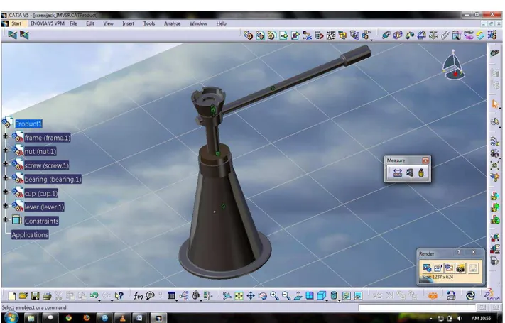
3D Model of the Designed SCREW-JACK:
Fig : screw-jack assembly( Drawn with CATIA V5)
REFERENCES:
[1] C. S. Sharma;Kamlesh Purohit, Design of machine elements ,page-243,PHI Learning Pvt. Ltd. [2] VB BHANDARI, DESIGN OF MACHINE ELEMENTS,Page-184,Tata McGraw-Hill Education. [3] http://www.scribd.com/doc/36883255/Power-Screw