Investigation of the use of Ishiagu Galena Concrete in E-M Radiation
Sheilding
Gabriel Ndubisi EGWUONWU1*, Paul Hena BUKAR2, and Abraham AVAA1
1
Department of Science Technology, Nigeria Institute of Leather and Science Technology, Zaria, Nigeria
2
Department of Physics, Ahmadu Bello University, Zaria, Nigeria
E-mail(s): gabneche@yahoo.com, paul.hena@yahoo.com, avaab2003@yahoo.com
*
Corresponding author: Phone: +2348036936068
Abstract
Galena samples, collected from Ishiagu, south-eastern Nigeria, were used to
make concretes for experimental radiation shielding. The concretes were
moulded into cylindrical tablets of various densities in order to ascertain their
attenuation capability to some electromagnetic radiations. Blue visible light
and gamma-ray (455-500 nm) sourced from cobolt-60, were transmitted
through the concretes and detected with the aid of Op-Amp and digital
Geiger-Muller Counter respectively. The absorption coefficients of the
samples of thicknesses in the range of 1.00 mm – 5.00 cm were determined.
Results obtained show that a typical Ishiagu galena concrete of about 2.80
g/cm3 has the capacity of shielding visible blue light with about 2.51 mm
TVL and 0.81 mm HVL. It also shows that the concrete of similar density can
optimally shield gamma radiation with about 5.06 cm TVL and 1.53 cm HVL.
The results of the investigation however, suggest the shielding and
engineering properties of the galena sourced from Ishiagu. A database of
shielding strength for the insitu galena was established hence, can serve as
suitable platform for quality and quantity control in radiation shielding
technology and can be used in high voltage radiotherapy rooms and nuclear
reactors.
Keywords
Introduction
Radiations namely; ionizing and non-ionizing are capable of causing harm to man and
changing properties of certain materials. However, the challenge of ameliorating the problem
of harmful radiation in nuclear, X-ray and other related technology, has taken a lot of effort.
Hence radiation shielding is an important art applied in the use of some electromagnetic
radiations and most radionuclide. The essence of the shielding is to attenuate the harmful and
unwanted rays from exposure to users who work with them or close their sources [1,2]. Dense
materials such as the ore of Haematic (FRO2O2), magnetite (FeO4), Anglesite (PbCO3) or
Galena (PbS) can be used as aggregate of concretes meant for shielding [3].
Galena, a latin term for lead sulphide, particularly is named after Alaska which is also
known as the City of Galena. It is a sulphide mineral useful in diverse ways namely; in
making lead batteries, solder, TV tubes, glass, construction, communications and protective
coatings, X-ray and gamma radiation shielding, ballast/weights, electronics and ammunition.
Galena is a mineral of about 86.6% lead and 13.4% of Sulphur. Therefore it is one of the most
widely distributed of all sulphides and constitutes the most important ore for lead [4]. The
average hardness of galena is about 2.85 on mineralogy scale and it has a specific gravity in
the range of 7400 -7600 kgm-3. The melting and boiling points of it are 1114ºC and boils at
1290ºC. Galena crystallizes in isometric systems usually in cubes and sometimes in octahedral
form. It belongs to mesothermal (200-300ºC) deposits hence often occurs with admixture of
silver, bismuth, copper, zinc and selenium in veins of various hydrothermal crystalline or
sedimentary rocks. Optically, galena has a reflection coefficient of about 32.2% of white
light. Electrically, it is apparently an excellent intrinsic semi-conductor with energy gap of
about 0.4 eV having a conductivity of about 2×10⁻³ Siemens and optimally photoconductive
between 10,000 A and 30, 000A. Galena slows photoelectric effect that is sometimes positive
and sometimes negative [5].
In Nigeria, it can be found naturally in commercial quantities in Benue Valley which
is almost parallel to River Benue, spreading across Ishiagu and Abakaliki in Ebonyi State,
Gboko and Makurdi in Benue State, Arufe, Wukari in Taraba State, Awe Ibi and Filiya area
in Borno State. Ishiagu is Ishiagu District of Ebonyi State south-eastern Nigeria. The town is
bounded by longitudes 7°29’–7°35’E and latitudes 5°43’-5°51’N. The relief of Ishiagu
mining site is low-lying and undulating. The rocks are extensively fractured, folded and
faulted. The mineralization of the site occurs as series of closely spaced, steeply dipping
sub-parallel fractures which trend NW-SE. It is exclusively fissure-filling and distinctively
patterned in the NW-SE fractures and gangue minerals [6]. The site comprises sand, lenses of
sandstone and limestone, shale’s with fine grained micaceous sandstones and mudstones that
Galena which often occurs as fine granular aggregates and sphalerite are the dominant
constituents of the veins [6]. The distribution of Pb, Zn, and other heavy elements in Ishiagu
is due to their occurrence in veins and veinlets. Galena occurs in mineralized vein, mine
dumps, folded shales, the Asu River Shales and the minor basic intrusive [7].
Ishiagu is endowed with some mineral ore deposits namely galena (PbS) which serves
as major source of lead and sulphides in the area, sphalerite (ZnS), chalcopyrite (CuFeS2),
siderite (FeCO3), argentite (AgS) limestone (CaCO3) and cadmium sulphide (CdS) [6,8].
Galena obtained from Ishiagu locality is selected for study due to its satisfactory mechanical
property, availability, accessibility and relatively affordable cost. Galena concrete is an
aggregate bound together with other constituents namely sand, cement and water. It is made
to obtain various densities or thicknesses which will give satisfactory shielding properties to
radiation of high penetrating power. The concrete shielding properties may vary depending on
the composite of the concrete [9]. This investigation is therefore targeted on providing both
the quantitative and qualitative capacities of various densities and thicknesses of concrete [10]
of the galena sourced from the Ishiagu galena deposit. It is also is aimed at establishing a
database for the use of the Ishiagu deposit as a shielding material against radiation. The
investigation is expected to provide results which should aid decision-making on the design
and layout of shielding blocks casts in reactor shielding wall [11]. Hence the investigation
will invariably offer both technical and economic advantages to shielding technology.
This research is therefore aimed at ascertaining the extent to which the Ishiagu Galena
concrete could attenuate visible blue light and gamma radiation.
Material and Method
When electromagnetic radiation passes through matter, photoelectric effect, Compton
scattering and pair production interactions usually occur [12]. The predominant interaction
depends on the density of the material and the radiation intensity. After the interaction, the
intensity of the radiation reduces due to absorption [13]. The degree of interaction between
the radiation and the charges contained in the material is dependent on whether the charges
are tightly bound as the inner shell electrons of lattice ions or of the lattice ions themselves,
loosely bound as the outer shell electron of lattice ions or free electrons as are the conduction
electrons in a metal or semiconductor. For certain wavelength of radiation, the diminution of
intensity depends exponentially on both the length of the optical path in the absorber and the
absorption coefficient which is a constant for a given substance. Therefore for a material of
I=Ioe -ìt
(1)
where Io is the initial intensity, ì is the attenuation coefficient. The decrease in the intensity dI
of the beam of initial intensity I0 when in transverse through a small thickness dt of the
material is:
dI=-ìdt (2)
Such that:
∫
I =−∫
I t t 0 o dt μ μ I dI (3) Hence:
[ ]
[ ]
t0 I
I μ t
ln 0 = (4)
Therefore:
t
μ
0e
I
I= − (5)
When constituents are added to galena, they act as impurities. The impurity amount
changes the intrinsic property of the galena. The change in intrinsic property results to either
or increase or decrease in the energy gap which eventually increases or decreases the
conductivity and absorptive property of the concretes [14]. This is the basis for serve as the
basis for the evaluation of the shielding property of galena concrete by the estimation of its
absorption coefficient [15].
The relation for the absorption coefficient ì which measures quantitatively, the
properties of the various radiation concrete shields can be expressed as:
t in increase V V ln in increase μ t 0 − = (6) or: t in increase N ln in increase
μ= − (7)
where Vo and No are the voltages or number of counts measured before traversing a material
medium of thickness “t” whereas Vt and N0 are the voltages or number of counts measured
after the same depending on what kind of irradiation is measured: electrical or nuclear. Also,
the thickness of the shield which reduces the radiation to one-tenth of incident energy on it
μ 1 . 0 ln t 0 i i = (8)
While, the Samples of galena were collected from manually excavated deposits by
local miners and from existing Ishiagu mining companies. Galena thickness of the shield
which reduces the radiation to one-half of that incident on it, known as the one-Half Value
Layer (HVL) of the shield is given as:
μ2 i ln t 2 i = (9)
It is commonly required in nuclear technology that the shielding capacity of materials
in terms of the thickness of it which reduces the radiation to one-tenth (T.V.L.) or half
(H.V.L.) of its value of its incident intensity is evaluated.
Portland cement, sand, water, measuring cylinder, weighing balance, grinding
machine, plastic moulds, moulding machine, hand trowel, pestle and mortar were used in the
making of galena concrete. The introduction of the other constituents to the aggregate
(doping) was to make the galena extrinsic from it intrinsic nature. Lumps of galena were
finely ground and sieved with a 0.4 mm sieve. The sand was sieved with a 2.0 mm sieve and
the aggregate galena, sand and cement were weighed separately and thoroughly mixed. Water
was measured in a measuring cylinder, weighed, added to the aggregate, thorough mixing of
the aggregate was further carried out and finally, the concrete was poured into the plastic
mould and the precast was left to set for five days at room temperature. Six sets of various
thicknesses of the concrete of the same diameter were moulded. Secondly, six sets of the
concrete were prepared using constituents of various densities. Table 1 shows the constituents
of the aggregate concretes for the six sets of the samples.
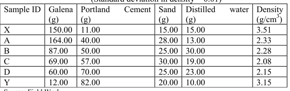
Table 1. Constituents of the Various Sets of the Galena Concretes Samples
(Standard deviation in density = 0.01) Sample ID Galena
(g) Portland Cement (g) Sand (g) Distilled water (g) Density (g/cm3)
X 150.00 11.00 15.00 15.00 3.51
A 164.00 40.00 28.00 13.00 2.33
B 87.00 50.00 25.00 30.00 2.28
C 69.00 57.00 30.00 19.00 2.08
D 60.00 70.00 25.00 23.00 2.15
Y 12.00 82.00 20.00 10.00 3.15
The constituents added to galena were meant to act as impurities which varies in
concentration in the various samples prepared hence changing the intrinsic property of the
galena. The changes in the intrinsic property cause an increase or decrease in the energy gap
which will either increase or decrease and absorption of the material. These effects serve as
the basis for the evaluation of the shielding property of galena concrete on the measurement
of the absorption of various samples of galena concrete by the estimation of their absorption
coefficient.
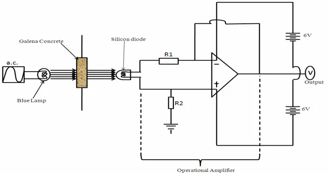
Two methods were used in the investigation of the shielding properties of galena
concrete namely; electrical and nuclear methods. In the electrical method, two power sources
were adjusted to about 6 Volts with the aid of a voltmeter. The pair of power supply was
connected in series with the operational amplifier [16], (figure 1).
Figure 1. Schematic set up of the investigation using the Operational Amplifier
(Source: Laboratory Experimental Design)
The input of the operational amplifier was connected to the negative terminal of
silicon diode, the output to the voltmeter whereas all the negative terminals earthed. The
average output voltage was taken before the samples were positioned for irradiation. The
circuit was closed and the light source was on. Deflection occurred on the voltmeter for little
change and was recorded. The average voltage change between the closure and opening of the
circuit “Vo” which corresponding to the intensity of the blue light source was recorded. While
the system was shielded from environmental light in order to drastically minimize error,
several measurements were taken and the average voltage of (V0 = 1.0 V) for the blue light’s
densities ranging from 2.08 gcm-3 to 3.51 gcm-3 and various thicknesses, ranging from 1.00
mm to 5.00 mm, at interval of 1.00 mm, were tested by the irradiation of the samples of the
concretes using the blue lamp. The deflection on the voltmeter due to the intensity of the light
received by the silicon diode after the radiation has traversed through the material, were
recorded. Each datum collection was repeated as much as possible in order to minimize error.
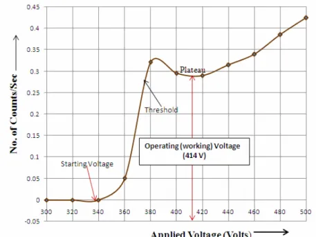
In nuclear method of the experiment, the voltage characteristics and the background
count of Geiger counter were first of all determined so as to adequately estimate of the best
operating voltage of it. Secondly, the emission rate of cobalt-60 was determined and finally
the effect of the galena concrete on the emitted radiation traversing it was investigated. After
warming the digital Counter for about 3 minutes, the voltage was adjusted gradually from 300
V with an increment interval of 20 V to 500 V. It was noticed that the Counter commenced
counts from 360 V hence; the average number of counts per 10 seconds was recorded. The
counts gradually increased with increasing voltages, at a particular range and later remained
almost constant (between 390 and 438 Volts). Afterwards, it resumed the increase in counts
with increase in voltage again. The mid value of that range (414 Volts) at which the counts
almost remain constant was considered as the best operating voltage of the Geiger counter
and was used to determine the background count (figure 2). The numbers of pulses counted
per 20 seconds were recorded and this was repeated fifty times. The cumulative average of
the number of counts per the fiftieth time (1000 seconds) was estimated to be 0.348
counts/sec as the background count of the Geiger counter.
Afterward, cobalt-60 was placed and exposed to enter the Geiger-Muller tube directly
without any concrete as a shield. The effective number of counts per 20 seconds was taken
and 50 counts of the exactly the same duration and this was estimated to be 3.484 counts/sec.
Finally, each of the concrete shields of various densities ranging from 2.08gcm-3 to 3.51 gcm-3
and various thicknesses ranging from 1.00 cm to 5.00 cm, at interval of 0.50 cm, were tested
by the irradiation of the samples of the concretes using gamma rays. The shielding properties
of the galena concretes were investigated as they were placed between the source and detector
and irradiated by gamma flux.
Results and Discussion
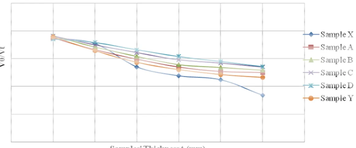
Results of the two experiments were tabulated and plotted on a two-dimensional
graph. From the plot of Vo/Vt against thickness of shields “t” (figure 3), each concrete shows
a curve which starts from t = 1.0 mm corresponding to V0/Vt~1.75 and decreases
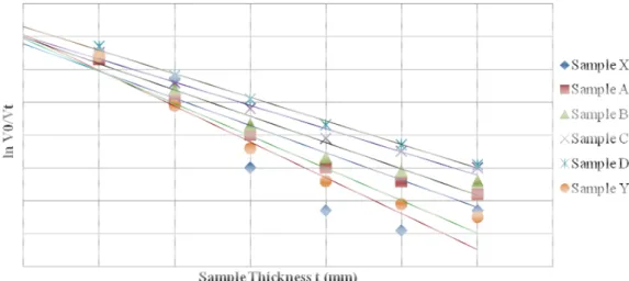
exponentially towards the t axis with the t axis as an asymptote. Figure4 shows the plot of the
logarithms of the V0/Vt against the various thicknesses “t” of the shields.
Figure 3. Plot of Vo/Vt against Thickness of Shield t
Figure 4 which shows the graph of ln Vo/Vt against thickness “t” of the shields shows
straight lines having negative gradient for the various thicknesses of the concrete shields. The
plot shows that the densities of the concrete shields have direct proportionality with the
attenuation of the radiation intensity reaching them. Hence the gradient of each line (figure 3)
equals the absorption coefficient for each set of the concrete of common density. The graph of
particular density, there is a curve starting from t = 1.0 cm and N~ 0.70 which exponentially
decreases with thickness and is patterned as an asymptote to t-axis.
Figure 4. Plot of ln V0/Vt against the Thickness of the Samples
The results of the Geiger counter as the concrete shields were irradiated were also
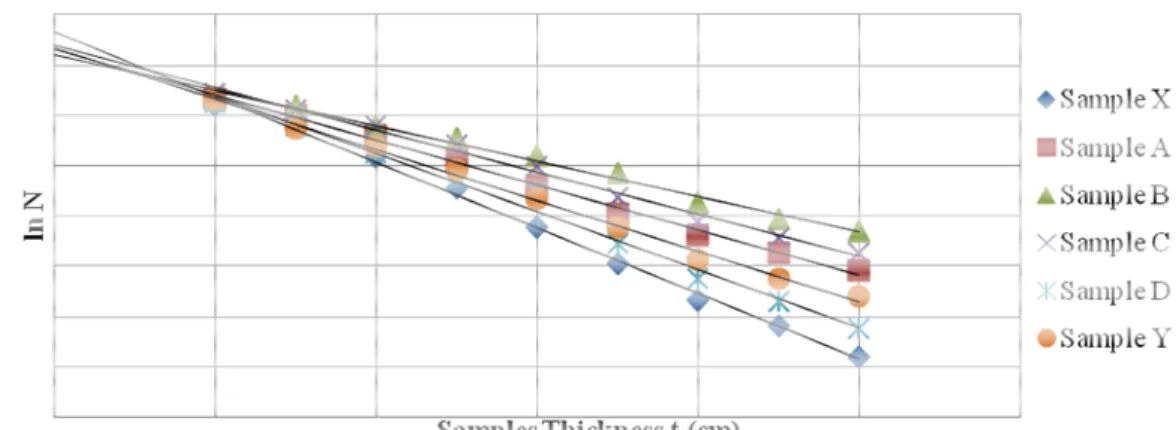
tabulated and plotted. Figure 5 shows the plot of the number of counts N against the various
thicknesses “t” of the samples for the various densities of the concrete shields while Figure 6
shows the plot of the logarithm of N (ln N) against the various thicknesses “t” of the samples.
Figure 5. Plot of the Numbers Counts N against thickness of Samples
The graph of ln N against thickness of shield “t” (figure 6) shows that for each
concrete density, there is a straight line with negative gradient. Hence the gradients of the
Figure 6. Plot of ln N against the Samples' Thickness
Table 2 shows the summary of the results’ interpretation vis-a-vis the absorption
coefficient, tenth value layer and the half value layer of the galena concrete in the two
methods of the investigation.
Table 2. Summary of the Results on the Investigation of the Shielding Capacity of
Ishiagu Galena Concretes
Samples’ ID
Density (g/cm3)
EM Radiation: Blue Visible Light EM Radiation: Gamma Ray ((455-500 nm) 1.33 MeV)
Absorption Coefficient (ì) (T.V.L.) 0 i i
t (mm)
(H.V.L.)
2
i
t (mm)
Absorption Coefficient (ì) (T.V.L.) 0 i i
t (cm)
(H.V.L.)
2
i
t (cm)
X 3.51 -0.108 2.132037 0.641806 -0.650 3.542462 1.066385
A 2.33 -0.082 2.808049 0.845305 -0.448 5.139732 1.54721
B 2.28 -0.080 2.87825 0.866438 -0.350 6.578857 1.980429
C 2.08 -0.070 3.289429 0.990214 -0.418 5.508612 1.658254
D 2.15 -0.071 3.243099 0.976268 -0.579 3.976857 1.19715
Y 3.15 -0.098 2.349592 0.707296 -0.505 4.559604 1.372574
Based on the interpreted data in Table 2, it can be observed that for the range of
density 2.08-3.15 g/cm3 of the galena concrete, T.V.L. to the blue visible light ranges between
2.13 mm and 3.29 mm while H.V.L. to the same ranges between 0.64 mm and 0.99 mm.
These results imply that on the average, the concrete of about 2.80 g/cm3 has the capacity of
shielding visible blue light with about 2.51 mm T.V.L. and 0.81 mm H.V.L. To gamma
radiation, galena concrete of similar density range has T.V.L. and H.V. L. in the ranges of
3.54 to 6.58 cm and 1.07 to 1.98 cm respectively. These results also imply that on the
average, the same concrete of about 2.80 g/cm3 has the capacity of shielding gamma radiation
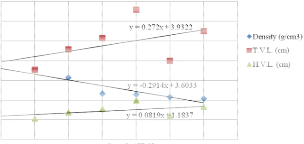
blue visible light, as concrete’s density decreases by -0.291 g/cm3, corresponding increment
in T.V.L. and H.V.L. are at 0.243 mm and 0.073 mm respectively (figure 7). On the other
hand, to gamma radiation, density decreases of the concretes at -0.291 g/cm3, corresponds to
increment in H.V.L. and H.V.L. at 0.272 cm and 0.081 cm respectively (figure 8). These
imply that incident intensity of EM sources can optimally be shielded, housed or stored,
reacted or conveyed using a typical Ishiagu galena concrete. For instance, gamma beams
which are of high intensity can be extracted to an experimental hall (HD-hall) and transported
to a production target. The conveyor in form of beam line tunnel is usually required to be
made of concrete shields in the HD-hall [17] hence offering advantages to shielding industry.
Figure 7. Comparative Plot of T.V.L., H.V.L. and the Density of Ishiagu Galena
Concrete in the Electrical Method
Figure 8. Comparative Plot of T.V.L., H.V.L. and the Density of Ishiagu Galena
Therefore, a typical Ishiagu galena concrete of about 2.80 g/cm3 has the capacity of
shielding visible blue light with about 2.51 mm T.V.L. and 0.81 mm H.V.L. Also, with about
5.06 cm T.V.L. and 1.53 cm H.V.L., the Ishiagu galena concrete can optimally shield gamma
radiation. Investigation has also confirmed that shielding strength of the concretes varies
directly with their thicknesses and densities. These data invariably support and aid the design
and modelling in commercial production of shielding materials particularly where galena
concrete are doped. Hence results obtained in the foregoing are expected to aid
decision-making on the design and layout of shielding blocks cast such as reactor shielding wall
thereby have offered both technical and economic advantages to industry.
Conclusions
The shielding effect of galena concrete walls based on the foregoing investigation is
sufficient for providing useful barriers to electromagnetic radiations which are capable of
causing harm to living organisms, even of high penetrating power. It therefore implies that the
application of galena concrete in the making of walls of conventional building materials can
optimize the building E.M. shielding capacity. Therefore to radiotherapy rooms, nuclear
reactors and similar houses, the estimated shielding capacity of dense materials, even though
they may not provide all the shielding necessary in given walls, is of valuable importance in
modern times.
References
1. Profio A.E., Radiation Shielding and Disimetry. A. Wiley- Intersaence Publication. John
Willey and Sons, New York, pp. 409, 1978.
2. Cember H., Introduction to Health Physics. McGrawHill, New York, pp. 99-107, 1992.
3. Kase K.R., Nelson W.R., Fasso A., Liu J.C., Mao X., Jenkins T.M., Kleck J.H.,
Measurements of accelerator-produced leakage neutron and photon transmission through
concrete. Health Phys, 2003, 84, pp. 180-187.
4. United Nations, Review of Scientific Information on Lead, Environment Programme,
5. Mortazavi S.M.J., Mosleh-Shirazi M.A., Maheri M.R., Yousefnia H., Zolghadri S.,
Hajipour A., Production of an economic high-density concrete for shielding megavoltage
radiotherapy rooms and nuclear reactors, Iran. J. Radiat. Res., 2007, 5(3), p. 143-146.
6. Ezepue M.C., The Geologic Setting of Lead-Zinc Deposits at Ishiagu, Southeastern
Nigeria Journal of African Earth Sciences, 1984, 2(2), p. 97-101.
7. Ezeh H. N., Chukwu E., Small Scale Mining and Heavy Metals Pollution of Agricultural
Soils: The case of Ishiagu Mining District, South Eastern Nigeria. Journal of Geology and
Mining Research, 2011, 3(4), p. 87-104.
8. Duruibe J.O., Ogwuegbu, M.O.C., Egwurugwu J.N., Pollution profiles of non-metallic
inorganic and organic pollutants of drinking and potable waters due to mining activities
in Ishiagu (Ebonyi State) of Nigeria. International Journal of Physical Sciences, 2007,
2(8), p. 202-206.
9. Kharita M.H., Takeyeddin M., Al-Nassri M., Yousef S., Development of special radiation
shielding concretes using natural local materials and evaluation of their shielding
characteristics. Atomic Energy Commission, Damascus, Abstract of Scientific Research
Journal Article, pp. 58, 2008.
10. Trout E.D., Kelley J.P., Lucas A.C., Conventional Building Materials As Protective
Radiation Barriers. Radiology U.S., 2009, 76, p. 237-244.
11. Zaytsev L.N., Methods of Making Concrete Blocks for the Shielding Walls of Buildings
Housing Nuclear Reactors and Accelerators. BetonI Zhelezobeton; 2009, 5, p. 227-230.
12. Greening J.F., Fundamental of Radiation Dosimetry. Page Bros, Norwich Ltd. 2nd Ed. p.
18, 1985.
13. Ghoshal S.N., Nuclear Physics, Chand S. and Sons Company Ltd. Ram Nagar, New
Delhi-110 055, p.188-191, 2008.
14. Knoll G.F., Radiation Detection and Measurement. John Wiley and Sons, p. 787-788,
1979.
15. Connolly T.J., Fundamental of Nuclear Engineering, John Willey and Sons, New York,
p.135, 1978.
16. Sorenson J.A., Phelps M.E., Physics in Nuclear Medicine. Willey and Sons, New York,
17. Hirose E., Tanaka K.H., Takahashi H., Agari K., Ieiri M., Katoh Y., Minakawa M.,
Noumi H., Sato Y., Suzuki Y., Takasaki M., Toyoda A., Yamanoi Y., Watanabe H.,
Katoh K., Saitoh N., Saijyo M., Applied Superconductivity, IEEE Transactions Phys. Div.