International Journal of Electronics Communication and Computer Technology (IJECCT) Volume 2 Issue 6 (November 2012)
ISSN:2249-7838 IJ ECCT | www.ijecct.org 280
TRANSMISSION OF DATA USING POWER LINE
CARRIER COMMUNICATION SYSTEM
Jovita Serrao
Electronics and Telecommunication Sardar Patel Institute of Technology
Mumbai, India
Awab Fakih
Electronics and Telecommunication Anjuman Islam Kalsekar Technical
Campus New Panvel, India
Ramzan Khatik
Electronics and Telecommunication Anjuman Islam Kalsekar Technical
Campus New Panvel, India
Shaikh Afzal
Electronics and Telecommunication Anjuman Islam Kalsekar Technical Campus
New Panvel, India
Chaya Ravindra
Electronics and Telecommunication Anjuman Islam Kalsekar Technical Campus
New Panvel, India
Abstract— This paper serves as a general and technical reference to transmission of data using a power line carrier communication system which is a preferred choice over Wireless or other Home Networking technologies due to the ease of installation, availability of AC outlets, higher throughput, low cost, reliability and security. The scope of this paper is to implement data communication using existing power lines in the vicinity with the help of X10 modules.
Keywords- Interoperability; Home Automation, Throughput, X10 protocol, CEPC.
I. INTRODUCTION
To achieve communication between any two points, several paths are available. However, of lately the traditionally used channels have come to a saturation level and there was need to explore new kind of technology which is simpler to implement and is not as expensive as other related technologies. The basic idea of power line carrier communication system (PLCC) is to use the existing power cable infrastructure for communication purpose. Our system will mostly be implemented in small areas such as residences, offices, etc. and with the use of this system; various kind of devices can be controlled remotely. The main benefit of this system stands to the residential users of making their dream of automation of their house. With just a simple set up of a transmitter and receiver, and ensuring equal phase supply, one can control a host of devices and enjoy the leisure of living in a fully automated house. Another major factor is the ubiquity of the medium - power outlets are commonly found and available throughout the house or the office and may very well serve as communication nodes. The external electrical grid can also be used for many applications whose solutions provide many opportunities for equipment vendors and utilities to offer new services, features and products, cut costs of current services, fully automate manual processes and procedures. It can also be used to improve current products, monitor and collect valuable data, offer remote service options
and create new business and revenue streams utilizing the existing infrastructure [1].
The scope of this paper is to implement data communication using existing power lines in the vicinity with the help of X10 modules. The system basically consists of two modules, a transmitter and a receiver that can communicate with each other using the existing power cables in residential and commercial areas. This paper elaborates on only the transmitter end of the PLCC system.
The paper is organized as follows. Section II discusses various PLCC standards. Section III explains the technology used and Section IV presents the system design considerations. The applications are mentioned in Section V. We discuss the limitations of our system in Section VI and conclude in Section VII.
II. PLCC STANDARDS
There are various standards available that involve modulation of the signal using carefully selected frequency range. These standards also provide robustness to the system to work properly under any conditions, since power lines may have many undesirable influences on the communication systems [1].
These standards are briefly described as follows.
A. Consumer Electronics Power Line Communication Consumer Electronics Power Line Communications Alliance (CEPCA) is a PLCC standard being developed by Sony, Mitsubishi and Panasonic. CEPCA is expected to deliver speed up to 170 Mbps using existing power lines.
International Journal of Electronics Communication and Computer Technology (IJECCT) Volume 2 Issue 6 (November 2012)
ISSN:2249-7838 IJ ECCT | www.ijecct.org 281 power transmission and distribution network and/or in-building
electricity wiring. The standards will be developed in sufficient detail to allow interoperability between equipment from different manufacturers and co-existence of multiple power line systems within the same environment.
C. Home Plug Power Line Alliance
The Home Plug Power Line Alliance has defined a number of standards that are mentioned as follows.
Home Plug 1.0: specification for connecting devices via power lines in the home.
Home Plug AV: designed for transmitting HDTV and VoIP around the home.
Home Plug BPL: a working group to develop a specification for to- the-home connection.
Home Plug CC: Command and Control is a low-speed, very low-cost technology intended to complement the alliance's higher-speed power line communications technologies. The specification will enable advanced, whole-house control of lighting, appliances, climate control, security and other devices.
D. X10 Communication Protocol
X10 communication protocol is developed by Pico Electronics. It is an international and open industry standard for communication among devices used for home automation and domotics. It primarily uses power line wiring for signalling and control, where the signals involve brief radio frequency bursts representing digital information [2].
III. TECHNOLOGY USED
In our system we use the X10 protocol. The advantages of using the X10 protocol is that all the components are designed to work with the existing power lines. X10 products are available from a number of manufacturers, and the range of devices that are available provide a variety of applications that can be achieved using simple plug-in or wire-in modules.
Whether using power line or radio communications, packets transmitted using the X10 control protocol consist of a four bit "house code" followed by one or more four bit "unit codes", finally followed by a four bit "command". For the convenience of the users setting up the system, the four bit house code is labelled as one of the letters A through P (the first 16 alphabets) while the four bit unit code is label as a numbers 1 through 16.
When the system is installed, each controlled device is configured to respond to one of the 256 possible addresses (16 house codes * 16 unit codes) and it will then only react to those commands specifically addressed to it.
In use, the protocol may transmit a message that says: "select house code J", "select unit 13", and "turn on" and the unit set to address "J13" will turn on its device. Several units can be addressed before giving the command, allowing the command to affect several units simultaneously. For example, "select house code J", "select unit 13", "select unit 23", "select unit 27", and finally, "turn on". This will cause units J13, J23, and J27 to all turn on.
There is no restriction except possibly consideration of the neighbours that prevents using more than one house code within a single house. The "all lights on" command and "all units off" commands will only affect a single house code, so an installation using multiple house codes effectively has the devices divided into separate zones.
IV. SYSTEM DESIGN
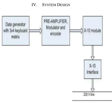
Figure 1. Transmitter Block Diagram
The basic block diagram of the transmitter for data communication using power line carrier communication system is shown in Fig. 1
The existing electrical layout is used to transmit the data or command for the proposed control system from one point towards other without any interference in the electrical signal within the same house. The system can be used to transmit a data signal in the frequency range of 3 KHz to 148.5 KHz.
International Journal of Electronics Communication and Computer Technology (IJECCT) Volume 2 Issue 6 (November 2012)
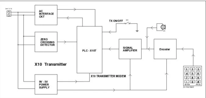
ISSN:2249-7838 IJ ECCT | www.ijecct.org 282 Figure 2. Detailed block diagram of transmitter
International Journal of Electronics Communication and Computer Technology (IJECCT) Volume 2 Issue 6 (November 2012)
ISSN:2249-7838 IJ ECCT | www.ijecct.org 283
V. APPLICATIONS
A. Accessibility
The power line communication finds many applications because of its easy accessibility. This communication can be stretched to areas where telephone lines cannot reach. .In advanced future prospects we may be able to enhance the system by providing multiple receivers.
B. Home Networking
PLCC can be used as a cheaper alternative to intercom.
C. Load Control
Many loads may be connected to the output instead of the speaker. These loads may be switches controlling the various appliances or it can be the relays that activate various security systems.
D. Home Automation
By using the loads as switched and controlling different appliances will give rise to the home automation technology for the new smart homes and offices [3].
Thus, the application and future prospects can be summarized as follows:
Low cost audio communication PC to PC file transfer
Intercom system
Industrial control system Home automation system Wireless security application
VI. LIMITATIONS
One problem with X10 is excessive attenuation of signals between the two live conductors in the 3-wire 120/240 volt system. Signals from a transmitter on one live conductor may not propagate through the high impedance of the distribution transformer winding to the other live conductor. Often, there's simply no reliable path to allow the X10 signals to propagate from one phase wire to the other; this failure may come and go as large 240 volt devices such as stoves or dryers are turned on and off. (When turned on, such devices provide a low-impedance bridge for the X10 signals between the two phase wires.)
This problem can be permanently overcome by installing a capacitor between the phase wires as a path for the X10 signals; manufacturers commonly sell signal couplers that plug into 240 volt sockets that perform this function.
TVs or wireless devices may cause spurious off or on signals.
Noise filtering (as installed on computers as well as many modern appliances) may help keep external noise out of X10 signals, but noise filters not designed for X10 may also filter out X10 signals traveling on the branch circuit to which the appliance is connected.
VII. CONCLUSION
With current available data transmission speeds of 14 Mbps and a remarkable increase promised in the near-future, Powerline Carrier Communication Systems are a preferred choice over Wireless or other Home Networking technologies due to factors including ease of installation, availability of AC outlets, higher throughput, low cost, reliability and security. PLC Communication Systems are also a potential candidate for the deliverance of xDSL and Broadband Internet services (data, multimedia etc.) along with electricity (and automation control signals) to the consumers by the energy utilities.
REFERENCES
[1] Stanley H. Horwitz, Arun G. Phadke, Power System Relaying, Third Edition, John Wiley and Sons, 2008 ISBN 0-470-05712-2, pages 64-65 [2] Edward B. Driscoll, Jr. ‗The History of X10‘
[3] Y. Koren, Y. Seri ―using LIN over power line communication to control truck and trailer backlights‖ – SPARC 2007