SST and ADITYA Tokamak Researh in India
Dhiraj Bora,ADITYA Team &SST-1 Team,
InstituteforPlasmaResearh,
Bhat,Gandhinagar-382428,INDIA
Reeivedon3July,2001
Steadystateoperationoftokamaksplaysanimportantroleinhightemperaturemagnetially
on-ned plasma researh. Steadystate SuperondutingTokamak (SST) programmeinIndia deals
withthe development ofvarioustehnologiesinthis diretion. SST-1[1℄ mahinehas been
engi-neeredandisbeingfabriatedattheInstituteforPlasmaResearh. Theobjetivesofthemahine
aretostudyphysisofplasmaproessesundersteadystateonditionanddevelopthetehnologies
relatedtosteadystateoperation. Varioussub-systemsarebeing prototypedanddeveloped. SST-1
isalargeaspetratiomahinewithamajorradiusof1.1mandaplasmaminorradiusof0.2mwith
elongationof1.7to1.9andtriangularityof0.5to0.7. Ithasbeendesignedfor1000seoperationat
3Ttoroidalmagnetield. NeutralbeamInjetionandRadiofrequenyheatingsystemsarebeing
developedtoheattheplasma. LowerhybridCurrentDrivesystemwouldsustain200kAofplasma
urrent during 1000 seoperation. ADITYA tokamak [2 ℄has been upgraded with new
diagnos-tisandRFheating systems. ThomsonSattering andECEdiagnostishavebeenoperated. 200
kWIonCylotronResonaneHeating(ICRH)and200kWEletronCylotronResonaneHeating
(ECRH)systemshavebeensuessfullyommissioned. RFassistedinitialbreakdownexperiments
havebeeninitiatedwiththesesystems.
Introdution
Tokamak researh in India has matured over the
years. Afterexperiementsonpulsedohmiplasmasin
ADITYA Tokamak, experimentson auxiliaryheating,
urrent drive and other areas of researh with high
power radio frequeny (RF) and mirowave soures
havebegun. At thesametime,amajorprogrammeis
underwaytostudysteadystateoperationoftokamaks.
With this aimin mindasteadystatesuperonduting
Tokamak(SST-1)hasbeendesignedandisbeingbuilt
at Institute for Plasma Researh, India. This paper
desribesthe present status of ADITYA Tokamak
re-searhandSST-1projet.
SST - 1 Tokamak
ThebasiobjetivesoftheSSTprogrammeare:
1. Torun SST-1Tokamakdishargesfor1000seand
to investigate physis issues related to heat removal
andpartileontrolattheboundaries.
2. Todevelopthetehnologiesrequiredtoahievethe
abovegoal.
Many of the onventional issues studied in Tokamak
physis will be addressed during operation in steady
statesenario. Partileandenergyonnementduring
nonindutive urrent drive in steady state operation
will be studied. Eet of impurity onnement and
ELMS on energy onnement in steady state will be
studied. Studies on stability limits, disruptions,
ther-malinstabilityandvertialdisplaementevents(VDE)
inPlasmawithnonindutiveurrentdrivewillbe
em-phasised. Study of dierent divertor ongurations
will form an important area of researh in the SST-1
programme. Some experiments in advaned tokamak
regimeswouldalsobeattempted.
Mahine features
SST-1hasamajor radious(R)of1.1 m anda
mi-nor radius of 0.2 m, a toroidal eld of 3.0 T at the
plasma entre and a plasma urrent of 220 KA. The
proposedplasmawillhaveanelongation()of1.7-1.9
andtriangularity(Æ)intherangeof0.4-0.7. Initially
hydrogen plasma disharges would be produed for a
maximumdurationof1000Se. Ohmi drivenplasma
urrentwouldbereplaedbylowerhybridwavedriven
nonindutiveurrentin the plasmato sustainthe
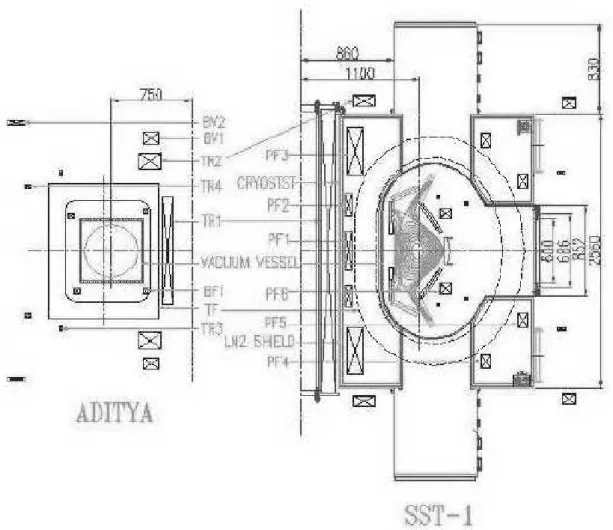
dis-hargefor1000Se. Fig. 1showstheomparisonofthe
Figure1. CrosssetionalviewofADITYATokamakandSST-1.
SST-1Mahinewouldoperatewith
superondut-ingtoroidalandpoloidaleldoils. Dishargewouldbe
initiated with the help of an ohmi transformerusing
opperoilsgivingavolt-seondsapabilityof1.4V
s. Anultrahighvauumompatiblevesselwouldhouse
theplasmafaingomponents. Ahighvauumryostat
would enlose all theSC oils and thevauum vessel.
To redue the heat load on SC oils Liquid Nitrogen
(LN
2
) ooled thermal shields would be used between
thevauumvesselandtheryostat.
Magnet system
The magnet system omprises of TF oil system,
PF oilsystem, ohmi transformer,vertialeld oils
and vertial postion ontrol oils. Position of various
Toroidal eld (TF) oil system
Thetoroidaleldoilsystemwillproduea3T
mag-neti eldontheplasmaaxiswith <2%ripple within
the plasma volume. The TF assembly has been
de-signedtooperateinsteadystateandwithstandplasma
disruptionsand VDEs withoutquenhing. The whole
assemblywillbeooleddownandwarmedupwithin15
days. TFoilsystemonsistsof16modiedDshaped
TFoilsarrangedgeometriallyaroundthemajoraxis.
These superonduting oils are wound from speially
designed NbTi / Cu CICC manufatured by Hitahi
Ltd.,Japan. A totalof 17.28MATat apeakurrent
of 10KA perturn will produeaeld of 3.0T at the
plasmaentreandamaximumof5.1TattheTF
on-dutor. EahTFoilismade ofsixdouble `panakes'
andeahpanakehavingnineturns. Inter-double
pan-akejointsareonventional solderedjoints. Cryogeni
gradeEglasstapeswithhalfoverlapareusedforturn
to turn insulation in panakes. NEMA grade G-11
impregnatedwith epoxyand thenshrunkttedinto a
stainless steel(SS316L)asingwhihsupports mostof
theeletromagnetiload.
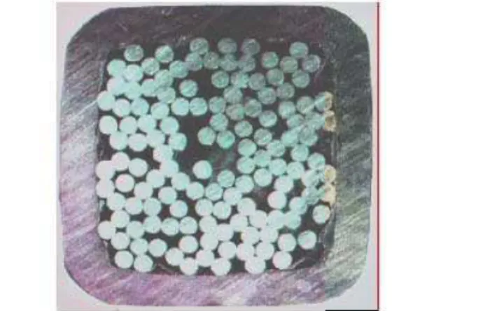
Figure2. ArosssetionalviewofSST-1CICCwith135
strandsinit.
TheCICCismade upof135strandsabledina3
335ablingpatternandonduitedinaSS304L
onduit(Fig. 2).
It is designed for an operational urrent of 10KA
at 5T and 4.5K,with a ritialurrentof 36KA. The
nominal ritialurrentforeahstrandis 272Aat5T
and4.5K.Thequaliationtestshavebeenarriedout
on strands at 5T and 4.2 K. Various tests have been
performed onthe strands. Dependene of strand
rit-ialurrentontemperatureforvarious elds isshown
in Fig. 3. Theresultsindiatethat degradationin the
strandsduetoablingandjaketingislessthan5%and
a ritial urrent of 35kA at 5T, 4.2 K is ensured.
Test onduted at Kurhatov Institute at Mosow on
a model oil fabriated out of 600 m long strand [3℄
indiate stabilityoftheondutorforTFoilsof
SST-1. Further tests havebeenperformedto establish the
limitontherampratesforvariousurrentlevelsinthe
ondutor.
AlltheTFoilsareonnetedinseriesandare
pro-teted against quenhing by a suitabledump resistor,
swithingandsensingsystem. Typialdumptime
on-stantis12seandthemaximumvoltagearosstheoils
at thedump timeis600Vwithrespetto ground.
The TFoils arefurther supported onabase support
systemonsistingofaringwith16aintileveredbeams.
Theringrestsoneightolumnsthatareinsidethe
ryo-stat andhaveLN2 intereptstominimize the
ondu-tion lossat 4.5 Kasthe oldmassload istransferred
fromtheseolumnstothemainmahinesupport
stru-ture. The main mahine support is omprised of 8
olumns,supportingthebaseframeoftheryostatand
Figure3. StrandCritialCurrentvsTemperaturefor
variouseld.
Poloidal eld (PF) oil system
Thedesignandoptimization ofthePFoilsystem
hasbeendonebasedonafreeboundary,axisymmetri,
idealMHDequilibrium model. ThePF Coilsystemis
omprisedof nineSCoils (PF1toPF5) andtwo
nor-mal opper oils (PF6). The PF6 oils are plaed in
theboreoftheTFoilsinsidethevaumvessel. They
arerequired to obtainplasma shapeswith high
trian-gularity. Inthe abseneof PF6oils,large number of
ampere turns are requiredin theexternal PF oils to
obtainsimilar triangularity. The PF oils allow for a
widerangeofelongationandtriangularityandsupport
wide rangeof plasma equilibria. Design goalsinlude
variousstartupsenario,feasibilityofsimilaroperation
duringplasma urrentrampup, double andsinglenull
operation.
Thedesigned PFsystemallows forplasma
elonga-tion in the range 1.7 - 1.9, triangularity in the range
0.4-0.7,plasmaindutaneintherange0.75-1.4and
poloidal in the range 0.01 - 0.85. A slot divertor
ongurationisalsoaommodatedinthedesign.
Ohmi transformer and Vertial eld
oils
An ohmi transformer, omprised of a entral
solenoid (TR1) and two pairs of ompensated oils
(TR2 and TR3) are used for plasma startup and
ini-tialurrentrampup. TheSCpoloidal oilsarenot
be-ing used as they demand that the rate of hange of
urrentsin these oils belimitedbelowaertain level
toavoidquenhingoftheseoilsduring startupphase.
Thereforetoestablishanequilibriumeldonafasttime
sale,theohmitransformerismadeoutofhollow
op-per ondutorsthat has astorage apaity of 1.4 V s
andwouldbeusedforproduingirular plasmawith
100KAurrentfor1seond duration. Apairof
TheurrentdrivewillthenbetakenoverbyLHCD
andthePFoilswillberampedupataslowrate,
typ-iallyin3sinapre-programmedfashiontoahievethe
desiredplasmaequilibrium. It willalsoprovidethe
di-vertorongurationforanelongatedtriangularplasma.
Feedbak ontrol oils
It iswellknownthat vertiallyelongatedplasmais
inherentlyunstabletoperturbationsinthevertial
di-retion. Toarrestthegrowthrateofthis instability, a
set of passivestabilizers are plaedinside the vauum
vessel. Thiswouldreduethegrowthrateto38Se 1
orrespondingtothemostunstableequilibriumfor=
1.9. Furtherstabilisationisprovidedbyativefeedbak
usingapairofoils plaedinside thevauum vessel.
These oils have amajorradius of 1.35m and are
onnetedinasaddleonguration. Theyaredisplaed
by0.5mfromtheequatorialplane. Duringlongpulse
operation,minorradialshiftsoftheplasmawillalsobe
takenareofbytheseoils.
Cryogeni system for SST - 1
TheSCmagnetswillbeooledusingforedowof
superritial helium (SHe) through void spae in the
CICC.A totalow0.3Kg/sisrequiredtokeepthe
SC temperature well below the urrent sharing
tem-peraturein thepreseneof peak pulsedloads. Vapour
ooledurrentleadsonnetthemagnetstopower
sup-plies. Heat the oldendevaporates to gasHelium at
300Katthewarmendofthelead. A Helium
refrig-erator /liqueer withold irulationsystemfor SHe
is beingset up for this purpose. LN
2
shields are
pro-vided betweenoldmassat4.5Kand warmersurfaes
tominimizetheheatloadsonmagnetsandsupport
sys-temat4.5K.ALN
2
storageanddistributionsystemis
provided forthis purpose.
Heat loads experiened by SC oils inlude steady
stateheatloadsandlossesduringoperation. Atotalof
180Wisestimatedasthesteadystateheatload.
Dur-ingaplasma pulse, SCoils aresubjetedto apulsed
loadof125KJ.Suhpulseswould berepeatedafter
eah 5000 se. for a maximum of six times during a
day. Suha loadwould evaporate 150L/hrof LHe
toheliumgasat300KintheurrentleadsoftheSC
oils.
AlosedyleLHeplantisbeinginstalledto ater
forboththesteady stateandthetransientheat loads.
Theplanthasarefrigerationapaityof650W at4.5
K, and 200 L/hr liquefationat a pressureof 1.2 bar
whihinludes theprovision of 250W refrigeration
apaityfortheheatdissipationintheoldirulation
pump. This apaityisahievedwithLN2preooling.
Itispossibletooperatetheplantwithoutpreoolingto
reduedapaity.
LN
2
ooled radiationshields areprovided between
the SC oils and the vaum vessel and between the
oils and the ryostat. Under dierent operating and
onditioningphasesthe LN
2
onsumption would vary.
Amaximumof1500L/hronsumptionisantiipated
for all the systems. Therefore ommerially available
LN
2
would be stored in tanks for distribution. Tanks
havebeenprouredandinstalled. Variousomponents
ofthedistributionline areunderfabriation.
TheheliumplanthasbeenprouredfromM/s. Air
Liquideryogenie,Frane. Itisunderproessof
instal-lation.
Vaum vessel, ryostat and pumping
system
The vauum vessel is being fabriated in sixteen
modules whih would be welded in situ. Eah
mod-ule onsists of a vessel setor, aninteronneting ring
and three ports. The vessel setor is plaed between
two TF oils while the ring setor is loated in the
boreoftheTFoil. Therearetotally32vertialports
and16radialports. Itisanultrahigh vauumsystem
withpartialpressures,forallgases,lessthan110 8
torr exept hydrogen. TheSS304Lvauum vessel has
aheightof1.62m,amidplanewidth of1.07m,atotal
volumeof16m 3
andasurfaeareaof75m 2
. The
ves-sel would bebakedto 525K. Other wall onditioning
tehniquessuhasdishargeleaning,boronizationet.
arealsoenvisaged.
Theryostatis asixteensided highvauum
ham-beralsomadeofSS304L.Abasepressureof110 5
Torrwouldbemaintainedintheryostat. Ithasa
vol-ume of35m 3
andsurfaeareaof59m 2
.
126m 2
surfaeareaofLN
2
ooledpanelsareplaed
between allsurfaes at temperatures higherthan 85K
and surfaes at 4.5 K. Panelsare formed of 8mm
di-ameter tubes vauum brazed to 1mm thik SS 304 L
sheets.
Duringnormaloperation10,000L/Spumpingspeed
isprovidedtoahieve110 8
torrbasepressure.
Sim-ilar speed is also provided for the ryostat. Two
tur-bomoleularpumps, eahwith5000L/Sspeed,willbe
used for thepurpose. Maingasload antiipated from
the Vessel is during steady state operation. For this
purpose,sixteenturbomoleularpumpseahwith5000
L/Sspeedat10 3
torrforhydrogenwillbeonneted
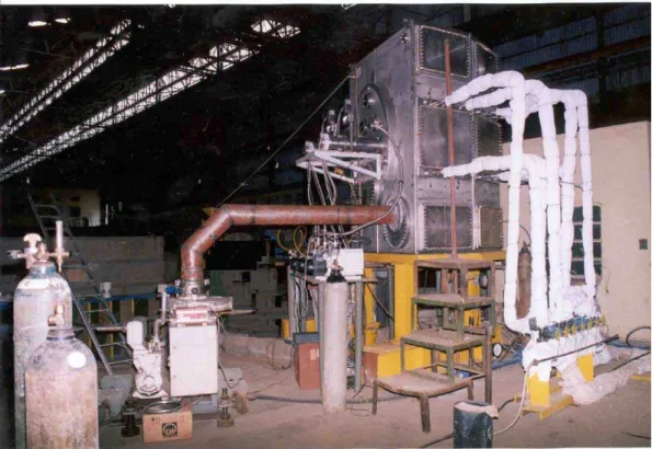
Figure4. AviewoftheSST-1proto-typebeingtestedinlaboratory.
Thevauumvesselandtheryostatwillbepumped
downfromatmospheripressureto10 3
torrusingtwo
separateRootspumps of2000m 3
/hapaity.
A prototype of one vessel setorwith ports, two ring
setors andoneeighthsetionoftheryostathasbeen
fabriated and tested suessfully at M/s. Bharat
HeavyEletrialsLimited,Tiruhirapalli,India,whih
has established all the proesses for nal fabriation.
Theprototypehasbeenshiftedtositeand ithasbeen
ommissioned in thevauum laboratory. Fig .4 shows
theproto-typesystemunder testing. Inthemeantime
fabriation ofthemain systemiswellunderway.
Central radial port of the vauum system along with
topandbottomportoftheryostatareseeninthe
pi-ture. All add onsystems will be tested forfuntional
ompatibilitywiththesystemonthisproto-type.
Plasma faing omponents (PFC)
Divertorsand baes, poloidal limiters and passive
stabilisers are the onstituentsof the PFC of SST - 1
[4℄. Heat andpartile removalduringsteady state
op-erationistheprimeonernduringthedesignofPFC.
Inboard and outboard divertorplates aredesigned for
theworstpossibleheat loadsbyassumingdierent
in-out and up-down asymmetry for the divertors. The
strikepointsis1.6and 5.6MW/m 2
,respetively. The
poloidal inlination of the outboard divertor plates is
adjustedsoastohaveanaverageheatuxatthestrike
points of less than the allowed limit of 0.6 MW/m 2
.
Thetargetpointsof theinboardandthe outboard
di-vertorplateshavebeenhosenatadistaneaslargeas
possiblefromthenullpoint. Thisreduestheeletron
temperatureat the targetplate and dereases the
im-purityuxfrom thedivertorregion. A loseddivertor
ongurationisahievedbyinorporatingabaethat
helps to inrease the neutral pressure in the divertor
regionand improvesneutralpartile reylingand
re-dueseletrontemperature. This geometry also helps
in eÆient pumping of the divertor region. The slot
widthhasbeendesignedbyusingneutralpartileode
DEGAS and the results have been onrmed by the
useof thePlasmaand neutraltransport oupledode
B2-EIRENE.
One of the main objetives of SST - 1 is to ahieve
steady state partile removal from the vessel during
steady state disharges with a steady state plasma
density of 1 10 19
m 3
, onnement time of 12ms.
Thepartile exhaustexpetedfromtheoreis 22torr
l/swith thedivertorregion pressureat 110 3
torr.
Thepumping speedrequiredfor thedivertorregion is
11,000l/s. With allthe geometrialfatorstakeninto
unertainty of partile onnement time, the divertor
pumpingsystemhasbeendesignedtoprovidea
pump-ing speed of 63,000 l/s at 1 10 3
torr pressure of
hydrogengasatpumpingportofthevauumvessel.
A pair of poloidal movable limiters is provided to
as-sist plasma breakdown, urrent rampup and urrent
rampdown, and to protetRFantennaeand other
in-vesselomponentsduringnormaloperation,VDEsand
duringdisruptions. Theinboardandoutboardlimiters
are designed to handle about 4% of the input power
duringsteadystateoperation. Asafetylimiteris
posi-tioned50mmawayfromtheseperatrixontheinboard
side. Plasmafaing surfaeof the outboard limiter is
designed withappropriate poloidal urvatureto avoid
interfereneduringdivertoroperation. Thelimiter
sur-faesaretoroidallyproledtoreduetheheatux.
Passivestabilizersofondutingstruturessurrounding
the plasma are provided to redue the growthrate of
thevertialstabilityand makeativefeedbakontrol
possible. Two pairs of stabilisers,one onthe inboard
andoneontheoutboardsideoftheplasmaareplaed
aboveandbelowthemidplane. Toallowplasmastartup
with an ohmi ux swing, an eletribreak is
inrop-orated. The topand bottom stabilizers areonneted
inthesaddleongurationwithaurrentbridgeatthe
loation of this break. They are designed to handle
heatuxesat0.25MW/m 2
.
Theplasmafaingsurfaesofstabilizerplates are
ov-eredwith20mm thikgraphite tiles. Ativeoolingis
provided tomaintaintheirtemperaturebelow150 o
C.
Isostatially pressed ne grain graphite is hosen as
the baseline armour material for the PFC of
SST-1. Copper base alloys suh as opper-zironium and
opper-hromium zironium are seleted as the
sub-stratematerial fordivertorand limiterassembliesdue
to their good thermal ondutivity, good mehanial
behaviourat elevated temperaturesfor longdurations
and high eletrial ondutivity at elevated
tempera-tures. The PFCs are atively ooled to keep surfae
temperaturelessthan1000 o
C.Theyarebakableupto
350 o
C.
Poloidal limiter system is being fabriated and is in
advanestageofompletion.
SST-1 Plasma shape extration
Due to very long pulse length (maximum of 1000
seonds) SST-1 ontrol system would need to exeute
dynamiontrolofdishargestoahievetheobjetives
ofthedisharge. Oneoftherstrequirementsforthisis
theneedto developmeansbywhihinformation
avail-ablefromthedishargeisproessedinrealtime(ofthe
time deisionsaboutthe disharge progress. Artiial
NeuralNetworktehniquehasbeenutilizedtodevelop
algorithms to extrat SST-1 plasma shape boundary
from magnetimeasurementsin realtime. Algorithms
havealsobeendevelopedforpreditionofmajorplasma
disruptionandforthepreditionofdensitylimit
bound-ary. These havebeen tested with ADITYA disharge
dataandfoundtogivesatisfatoryperformane.
A multi-layered feed-forward neural network (NN) is
used to extrat the tokamak plasma parameters from
external magneti measurements. It is also used to
optimize the number and loations of the magneti
diagnostis designed for the tokamak. The magneti
measurementswillbeutilizedtoahievereal-time
on-trolofplasmaposition,shapeandsomeglobalproles.
An NN with 93 inputs (omprising 23 ux loop
dif-ferenes, 24 pairs of normal and tangential magneti
probesand22Mirnovoils),25nodesinasinglehidden
layer and 17 outputs (the physial parameters of the
plasma)istrainedandtested,andtheresultsare
om-paredwiththetraditionalstatistialmethodoffuntion
parametrization (FP). Both tehniques appeared well
suitedforthepurpose,butadeniteimprovementwith
NNisobserved. Althoughsimulatedmeasurementsare
used in this study, ondene regarding the network
performane withatual experimental data isensured
bytestingthenetwork'snoisetoleranewithGaussian
noise of up to 10%. Finally, three possible methods
of rankingthe diagnostisin dereasingorder of their
importane are suggested, and the NN is used to
op-timize the magneti sensors designed for SST-1. The
resultsfromthethreemethods areomparedwithone
anotherandalsowith FP. Magnetiprobeswithin the
plasma faing side of the outboard limiter are ranked
high. FPandoneoftheNNmethodsshowedadistint
tendeny to favour the probes loated in the remote
regions of the vauum vessel, proving the importane
of redundany. Fault tolerane of the optimized
net-workistested. Theresultsobtainedshould,inthelong
run,helpinthedeisionregardingthenaleetiveset
of magneti diagnostisto be used in SST-1for rapid
reoveryofplasmaontrolparameters.
Current drive and auxiliary heating
Radio Frequeny (RF) [5℄ and Neutral Beam
In-jetion (NBI) [6℄ methods are planned in SST-1 for
nonindutive urrent drive and plasma heating. Two
main fatorshavebeenonsideredduring the
develop-mentoftheseauxiliarysystems,namely,highheatux
(1 MW/m 2
) inident on the plasma faing antennae
omponentsandfastfeedbakforonstantpowerinput
experiments. RF break down and wall onditioning
have proved very beneial in tokamak operation. It
is speially useful for wall onditioning between long
plasma shots in mahines with SC toroidal eld oils
wheretheeldisnotrampeddownaftereahshot. At
highdensities,fastwaveurrentdriveintheoreofthe
plasmaprovesadvantageousthanlowerhybridurrent
drive. Eletronylotronurrentdriveisalsousefulfor
prole shaping. These onsiderationshavebeentaken
intoaountduringdesignoftherfsystemsforSST-1.
Lower hybrid urrent drive (LHCD)
sys-tem
LHCDsystemwould beusedastheprime method
of steady state plasma urrent drive in a irular as
well as an elongated plasma. The system has been
optimised for eÆient urrentdrive for 1.5 T and 3.0
T operation, for dierent plasma elongation and
tri-angularity,and forplasmaindutane valueof0.75to
1.4. Lower hybrid waves with asymmetri spetrum
(N
k
1.8 - 4.0) would be launhed by hanging the
phasebetweenadjaentwaveguidesfrom40to160
de-greesusing high powerphaseshiftersthrougharadial
port at3.7 GHzto driveplasmaurrentduring
dier-entoperatingsenarios. Computational analysisusing
LSC and WDFPodesshowthat 220kAplasma
ur-rentwould be drivenwith available powerof 1.1 MW
for irular plasma at 2 10 13
m 3
average density
and 3Ttoroidalmagneti eld. For thesamemahine
andplasmaparametersandplasmaurrent,860kWof
poweris suÆientifthe plasmaisheated byauxiliary
ICRH power of 650 kW. Sine the launher is made
of two rows of narrow waveguides, they ould be fed
withequalpowerandindependentlyphasedatdierent
anglesso astoradiatedierentspetra. Undersimilar
onditionsit ispossibleto drivethesameplasma
ur-rentatatotalinputpowerof600kW.Currentdriven
for a shaped plasma is being estimated with the help
ofACCOMEode. 1MWofCWpowerwouldbe
sup-pliedfromtwoklystronsto feedagrillonsistingof64
narrowwaveguidesintworowsplaedontheequatorial
planeofLFS radialport.
The main omponents of the system are low power
setion, high power amplier (klystrons), high power
transmissionline,highpowerphaseshifter(tovarythe
launhedspetrum),highpowerdiretionaloupler(to
monitorforwardandreetedpower),vauumwindow
andgrill. EahThomsonCSFklystron(TH2103D)
op-eratesat3.7GHzanddelivers250kWeahintwoarms
of WR284waveguidefor 1000se. Thepowerlevelin
eahofthe64hannelisaround15kWandisdenitely
the plasma through the grill interfaed by a vauum
windowassembly. Fourdummy waveguidesof quarter
wavelengthareatthefourornerstoreduefringeeld
eet. A protetion limiter is plaed around the grill
toprotetthe launherfrom diret partileload. It is
proposedthatthegrillwouldbepositionedat1.3
n (
orequivalently at 3.25
Q
behind the LCFS). Due to
theheat loadon the tiles and under onstant ooling
the temperatutre rise of the tiles are envisaged to be
about310degree.
Zr-Cropper,withhighthermalondutivityandhigh
tensilestrength hasbeenhosen forthe fabriation of
the grill to withstand the thermal stresses developed
due to the above disussed heat loads. Calulation
showsthattheestimated peak temperatureriseofthe
oppergrillis 116 o
Cproduing athermalstress of
220 MPa whih is below the yield stress for Zr-Cr
opper. Finite element ANSYS analysis onrms the
analytialulations. Disruptionstressanalysis shows
thatamaximumof13kNforewillbegeneratedon
the grill. The alulation is based on a simplemodel
whih assumes that 220 kA plasma urrent disrupts
within 0.1 mse(deay rate2.2 GA/ se). Similar
resultsareobtainedwithSPARKode(Eddyurrent)
analysis.
The vauum window whih aommodates 64 narrow
waveguides would be made out of 99.9Titanium
al-loy to avoid thermal raks and miroraks due to
dierentialthermalexpansion. Othertransmissionline
omponentslikeE/Hbend,transformer,narrow
waveg-uide havebeenprototyped, tested forhigh powerand
arebeingfabriated.
In the meantime two klystrons (TH2103D) have
been suessfully installed and ommissioned on
dummy loads [7℄. A test systemhas been established
aroundoneoftheseklystronstotesthighpower
ompo-nents. Intense klystron onditioningby applying high
voltagetotheeletrodeshasbeenondutedinthe
ab-sene of input rf power. Gradually the pulse length
and theapplied voltage is inreased. RF input is
ap-pliedonethetubesare onditioned. Beamurrentis
monitoredandtheoutputmirowavepowerismeasured
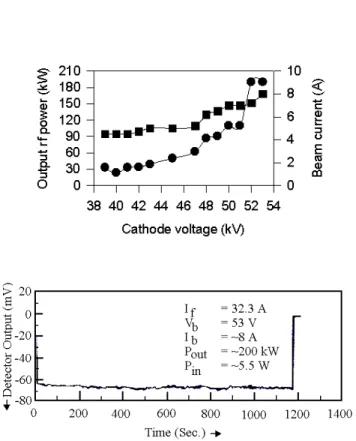
withthehelp ofdiretionalouplers. Maximumof200
kWoutput ismeasuredfor avoltageof -53 KVanda
beamurrentof9A.Operationislimitedduetothe
urrentapaity of10 A forthe HVDC powersupply.
Fig. 5showstheoutputpowerand beamurrentasa
funtion of athode voltage. Typial 1000 se, 200
Figure5. Figureontheleftshowsoutputpowerandbeam
urrent asafuntionof athodevoltage whereasgure on
therightshowsdetetoroutputorrespondingto200kWrf
powerfor 1000s.
Ion ylotron resonane heating (ICRH)
system
Ionylotron heating ishosen toheat theplasma
to 1.0KeV, during pulselengthof 1000s. A1.5 MW
ICRFsystemwouldoperateatdierentfrequenies
be-tween20-92MHz fordierentheating senariosat1.5
Tandat3.0Toperation.
Conventionaldesignriteriahavebeenimplementedin
developingthe1.5MW, 1000sRFsystem. Various
ef-ientheating senarios(e.g. 2nd harmoniof
major-ityspeiesat 1.5Tand3.0T,minorityD inH-plasma)
wouldbeimplemented. Thegeneratoristetrodebased
and modular. For the last high power stage, tetrode
has been seleted whih has wider frequeny
band-width. RF generator will be plaed in the generator
roomabout90m away.
A 90 m longpressurised 9", 50ohm transmission line
wouldfeedtheantennae. RFpowerisdividedby3dB
hybrid ouplerand then by two Tees to obtain equal
power at eah antenna. The entire transmission line
willbepressurizedat3bartoavoidbreakdown. Water
ow throughinner ondutorhasbeenseleted asthe
most optimized method after prototype testing. Slow
stub mathing (in ses) and automatimathing with
VVC (20-30mse) aswell asfast frequeny( 2ms)
ing during the disharge. Reeted power would be
replenished by inreasing the RF input power as per
the feedbaksignal tillslowmathing is ahieved.
In-terfaewouldbemadeofSS304Lforbettermehanial
strength and oated with opper( 100 )for better
rf transmission. For1000soperationinterfaewill be
atively ooled (full length of inner ondutor and a
narrowportionof outerondutor). Antennae are
de-signedusingtwopowerfulodesBRACCandSWHAP.
Fourantennae(eaharrying375kWofpower),plaed
on loweld side(out of neutralbeamsight) at3.5
q
behind the last losed surfae, will heat plasma to 1
KeV during 1000 s. Design goal for powerdensity is
1.2 kW/m 2
. Antennaisshielded from theplasma by
30no. of Faradayshields in asingleolumn. Antenna
assemblyismadeofSS304L.Graphitetileswillformthe
protetionlimiters aroundtheantennabox. Expeted
heatloadontheantennaassemblyis80W/m 2
.
Maxi-mumtemperatureatthegraphitetileswouldbe211 o
C.
Thermalanalysis hasbeenonduted with thehelpof
ANSYS for all the plasma faing omponents.
Maxi-mumthermalstress ontheantennaand onprotetion
tilesare330MPaand25MParespetively. Disruption
stress analysis shows that a maximum of 1.4 kNm of
torquewillbegeneratedontheantennastruture.
Im-purities generated due to physial sputteringof shield
material limits the power density. Analytial
alula-tionshowsthataelerationofionsintherfsheathdoes
notproduesigniantsputteredSSions.
Thesystem isin advaned stage of fabriation. 1MW
waterdummyloadiseretedand undergoing
ommis-sionat200kWlevelofRFpower.
Eletron ylotron resonane heating
(ECRH) system
ECRF system at 200 kW, 82.6 GHz will be used
initially to preionize and startupof SST-1 disharges.
A Gyrotron soure apable of delivering200 kW CW
hasbeenordered. Seondharmoni'X' and 'O'mode
launhingwouldbeusedduring 1.5Toperation.
Pro-visionforlowaswellashigheld sidelaunhhasbeen
made. Theoutputmodeofthegyrotronwithinternal
modeonverterisHE
11
. Atransmissionlineonsisting
of d.. break, bellows, mitre bend, polariserand
or-rugated waveguideterminating with abarrier window
will be used to transmit power from the gyrotron to
the tokamak. The total attenuationof the line is 1.1
dB.Quasioptialreetingmirrorsystemhasbeen
de-signedtosteerthemirowavegaussianbeamtoroidally.
LowFieldSidelaunheronsistsoftworeetors: one
fousingmirrorandaplanemirror. For longpulse
sep-to aomodate the reetors along with their ooling
arrangement. Similarlyin thetoplaunhsheme,two
mirrors(onefousingand oneplane)areusedtofous
thebeam. Thedistanebetweenfousingreetorand
bae is 1150 mm. A 25 mm aperture is provided in
thebaeforbeamentrane. Radiusofthebeamwaist
at the bae is seletedto be18mm. 14.5 % poweris
lost at the bae. The temperature rise of the
small-est reetor is around 350 o
C, taking 1 % absorption
of mirowave power on the reetor for 1000 seond
operation. Negligible part of EM power is absorbed
during O-modelaunhinitsrstpass. Afterreetion
fromthevesselwallthebeamisabsorbedintheentre.
Thebeamwaistradiusatthewallis29mmand
orre-spondingriseintemperatureofwallfor1%absorption
isapproximately700 o
C.Duringplasmadisruptionthe
EM fores experiened by the box, and its support is
2KN.Foreontheplanereetor dueto toroidaleld
omponentis20N/mwhiletheforeonthesupport
and reetordue toB
R
omponentis40N/m. The
foreontheplanereetorduetotoroidaleld
ompo-nent120KN.
The gyrotronandthe transmissionline is inadvaned
stateoffabriationattheontrator'splae. All other
subsystems are being fabriated inhouse after
proto-typetesting.
Neutral beam injetion (NBI) system
ThepowerrequiredinNBIinthelowandhigh
den-sityphases forSST-1 mahine is 0.5 and1.7 MW,
re-spetively. Thisrequirementwillbefullledby
tangen-tialinjetion ofthe beam, orrespondingto maximum
absorptionat0.98mradiusoftangenyintheplasma.
The beam parameters and their eet on the plasma
havebeenmodeledusingthe1-Dtransportode
BAL-DUR.HydrogenorDeuteriumbeamwillbeusedat30
-80keV.Theinjetionisexpetedtoraisetheion
tem-peratureto1keV,ontributetoafuellingof4torr
L/s,impart atoroidalmomentum of100km/s,and
drive aurrent of 40 kAat the oreof the plasma.
Thepowerwillbedeliveredfromasinglebeamlineand
thedynamirangeofvoltagewillbeaommodatedin
asinglesoure.
Engineering designs have been ompleted for the ion
soure, neutralizers I and II, deetion magnet,
V-target, ryogeni onversion system, LN
2
distribution
system,watersupplysystemandvauumvesselforthe
injetor systems. Thetenderdoumentsforalmost all
the omponents have been forwarded to the industry
fortheirtehnialproposal.
Theionsoureomponentleveldesignhasalreadybeen
arried outsuessfully. There havealso been
simula-tondouttheoptimalmagnetigeometryonthebak
plateforamaximumeldfreeregiononthebakplate.
Theneutralizer hasbeendesignedto dissipate atotal
powerof250KWinthetwostages. Thesystemis
de-signed to handle a gas throughput of 50 T l/s for
providinganintegratedlinedensityof0.35TorrCm.
Anativemagnetishieldingisprovidedontheseond
stageneutralisertoreduethestraymagnetields
in-sidetheneutraliserto <1G.
Detailedomputationsusing 2D/3D magnetmodeling
omputerodesandanalytialpartiletrajetory
alu-lations,using theeld distributions obtainedfrom the
abovementionedodes,haveledtothenalizationofa
largeiondeetion magnet system. Themajordesign
goalhasbeento getthe best possibleeld uniformity
andelddistributions inthe3diretions(z axisbeing
thediretionofpropagationofthebeam)foramagnet
havingtheleast possiblepole gap to pole depth ratio.
Ithasbeenfoundthat foraratioof1:2(30m/60m),
theobtainedeld uniformitiesare of theorder of1%
in the diretions prependiular to the beam diretion
and 6 % along the beamdiretion. Analytial
tra-jetoryalulationsindiatepowerdensitiesoflessthan
1kW/m 2
onthedumpsplaedatanangleof4 o
with
respettothevertial. Thealulationswillbe
benh-markedbydevelopingaprototypemagnethaving1/6 th
dimensionsas those for the main magnet. Vendor
-nalizationhasbeenonludedforthefabriationofthe
magnet.
V-targetonsistsoftwoarms,onehavinganassembly
of10andtheotheroneanassemblyof11HTE's. The
design allows for an angular movement of 7.2 o
about
hinge points of eah arm. Links mehanism is used
foropeningand losingboththearmssimultaneously.
To transfermotion from outside to inside of vauum,
abellowis used. Thewhole struture issupported on
asupport platform, whih is adjustable in height, by
30mm.
Engineering of the LN
2
and LHe distribution system
hasalsobeenarriedout. TheLN
2
distributionsystem
isbased onasimplesheme ofsupplying therequired
ow from a phase separator maintained at a working
pressureof1.8 bar. The phaseseparatoris lledbya
320l/h line branhed from the main line. The
distri-butionsystemforLN
2
ispresentlyunderfabriation.
A 4.5 Kto 3.8 KLHe onversionsystemsupplies the
liquid Helium through asub-atmospheri distribution
systemto theNBIryopumps. Theonversionsystem
isbasedonthesimpleoneptofpumpingontheliquid
Heliumforloweringthesaturationtemperatures. The
onversionsystem soures the liquid Helium from the
Figure6. Cryo-pumpfullsalefabriation.
Thefabriationofonemoduleofa10 5
l/sryo
on-densation pump has been ompleted. Thepump thus
manufatured is now ready for test of its engineered
performane.
Speial onsiderationshavebeenmade while deiding
ontheengineeringdesignofthedut,whihisaritial
systemfor longpulse beaminjetion. Modularity has
been inorporated in the design by the inorporation
ofstandardheattransferelementsto protetfromthe
powerux expeted dueto a re-ionizationlossof 3
%. Aritialelementin thedutisthetorus dut
iso-lationsystemwhihinorporatesa1mdiameterbellow
andaeramiisolatorratedfor5kV.
Prototypedevelopmentofpowersupplies
Oneofthemajorahievementshasbeenthe
devel-opmentofaprototypeofaregulatedhighvoltagepower
supply(RHVPS).A490kW(14kV,35A)RHVPShas
been suessfully tested. This has also led to the
va-lidity of several omponents like multi-seondary (20)
transformers, IGBT based swithed power supplies,
ontroller that initiates and regulates the funtioning
of the RHVPS with a fast dynami response time, a
menudrivenontrolonsolewithprovisionforvariable
riseandfalltimes,lowvoltageregulationandalow
rip-plewithoutanylter.
Development of a unique low voltage simulator will
serveas atest bed for anumberof model tests to be
arried out before implementation. The development
hasnowpavedthewayforthedevelopmentofa80kV,
8MW RHVPS requiredfor theauxiliary heating
sys-tems.
PrototypesoftheAr powersupply(AC/DC
onvert-have also been developed at the vendors site. The
salient features of the Ar Power Supply inlude low
urrentripple (low lossL-C lter design), use of PID
loop with alow drift for the load and line regulation
andIGBTswithesatnalstageforfastturnON/OFF
times. For the lamentpowersupply, the salient
fea-tures inlude a speial synhronisation iruit for
ob-taining a phase shift of < 10 between all 8 inverters,
userfriendlyinputandoutputontrolommandsanda
VariableVoltageConstantFrequenyinverterfor
min-imising thesize of thelament transformerat 400Hz
onstantfrequenyoperation.
Prototype development of heat transfer
2D nite element analysis related to thermal and
strutural properties lead to the design of the heat
transfer elements using the Cu-Cr-Zr alloy. The
elements are designed to dissipate a heat load of
15MW/m 2
. Repeated trials on the material and the
jointingproess(EBWelding)havenowledtothe
su-essfuldevelopmentofonemodule. Thishasundergone
tests for thermal yling. In the meantime the test
stand in theform of alarge vauum system hasbeen
fabriated and tested. Thesame isnowbeingereted
andtestedat site.
Diagnostis for SST - 1
Various diagnostis will be used in SST - 1.
Pa-rameterslikeplasmaurrent,position,shape,
p ,
den-sity, eletron and ion temperatures in the ore, edge
anddivertorregions,impurityonentrations,radiated
power,qprole,surfaetemperaturesof variousPFC,
utuations in the basi parameters over wide range
of frequeny will bemeasured. Long pulse operations
haveimpliationsonthediagnostistehniques.
Other diagnostis inlude FIR interferometer,
Thom-son sattering, ECE, harge exhange, thermography,
softandhardx-raymonitoring,visibleandVUV
spe-trosopyand motional starkeet (MSE)diagnostis.
TheMSEdiagnostiswillutilizetheNBIsystemofSST
-1.
Thomson sattering system
Forthetemporalevolutionoftheeletron
tempera-ture(T
e
)anddensity(n
e
)prolesover1000seSST-1
plasma,amulti-point,multi-pulseThomsonsattering
diagnostissystemhasbeendesigned. Inordertohave
a better understanding of the plasma parameters, it
has been deided to probe the dierent regions with
spatialandtemporalresolutionsasgivenintable. For
ahieving theabovetask three suh Thomson
satter-ingsystemshavebeendesignedforSST-1,namely:
1. VertialImagingSystem(VIS)
2. HorizontaltangentialImagingSystem(HTIS)
3. DivertorImagingSystem(DIS)
These three systems will together over a parameter
range of, n
e
1 10 12
m 3
and T
e
: 20eV to 3.5
keVoverthe1000seond plasmaduration.
Plasma Spatial Timeresolution Spatial Spatial Measurement
region overage resolution points durations
Core Partial -33mse 1m 19 1000seonds
(vertial (Z=-24 5.5mse{Burst
prole) to +24m) modewith1mse.
Coreand Full(from 33mse 1matore 19 1000se.
Edge inner to 5.5mse and0.5mat
(Midplane outer Burstmodewith atedge
tangential separatrix) 1mse.
prole)
Divertor Full(from 33mse 1m 10 1000se.
region X-pointto 5.5mse.
theplate Burstmode
with1mse.
Table1: TableshowingthespatialandtemporalresolutionforThomsonsatteringsystem
The systemsare in advane state ofprourementand
fabriation.
Zeeman polarimetry
This diagnosti involves the measurement of the
poloidal elddistributionthat wouldyield theplasma
urrentdensityprole. Thisinformationisessentialfor
understanding onnement, stability and energy
bal-aneof tokamakplasmas.
proles, whih are dominated by the thermal eet,
the irular polarization assoiated with the spetral
line, whih is proportional to the omponent of
mag-neti eld along the diretion of observation is
mea-sured. The absolute strength of the magneti eld is
obtainedfrom thediereneinintensitiesbetweenthe
rightandleftirularlypolarizedomponentswhen
ob-servedalongthemagnetielddiretion.
Intensity alulationsfor the intensity prolesfor
He-II(Aditya) and C-VI(SST-I) have been suessfully
ompleted. Based on it theoneptual design for the
engineeringdesignisompleted,experimentforthe
He-II lineonAdityawouldbeperformedbeforeinstalling
thesameonSST-Imahine.
Spetrosopy diagnostis
ThespetrosopydiagnostisforSST-1,duringthe
initialoperationalphasewill onsistofthefollowing:
A 0.3 m grazing inidene spetrograph with 3
inter-hangeable toroidal gratings (15 - 170 nm, resolution
0.4nm,10-110nm,resolution0.3nm,and10-30nm,
resolution< 0.1nm). Thisspetrographwill beUHV
oupledtothetokamakandviewaentralradialhord.
It will be equippedwith an ICCD detetor apableof
reordingthefullspetralrange(mentionedabove)
ev-ery10millise.
A 1 meter multi-trak visible spetrograph equipped
with a CCD detetor ahieving a resolution of 0.05
nmover300-800nmwillbeused. 8optialberswill
beused to transport lightfrom various regionsof the
tokamaktotheentraneslitofthespetrograph
simul-taneously. Spetraofwidth15nmenteredaroundany
seleted wavelength, from eah of the 8traksan be
reorded every150millise. Bylimitingto onetrak,
spetraan bereorded every 10 millise indenitely,
ora"burst"of8spetraanbereordedwithinabout
10milliseonds,whihanberepeatedaboutevery150
millse.
A plasma imaging system will be set up to view the
ross setion of the torus almost tangentially through
oneoftheradialviewports. Aoherentberopti
bun-dle onsisting of 10miron berswill arrya redued
image of the plasma to a 25 frames-per seond CCD
amera. The spatial resolution at the objet plane is
expetedtobeabout2.5mm.
Asimilarsetupforin-situilluminationandinspetion
oftheinsideofthetokamakis alsobeingenvisaged.
Forontinuousmonitoringofanumberofseleted
spe-tral lines ofHydrogen,and lowionization statesofO,
C, et. , so as to estimate the uxes of these speies
from various plasmafaingsurfaes,lterbased PMT
detetorswill beused. About12suh hannelshaving
atemporal resolutionof 1millise and5hannelsof
10miroseresolution, are planned. The latterones
will be utilized forthedetetion offast plasmaevents
likeVDE's,Elms,L-Htransitionet.
Thevariousoptialomponentsandeletronisneeded
fortheabovediagnostisarebeingidentied,proured
and assembled. The issuesrelated to data aquisition
at high rates and for long duration are being worked
out.
IR Thermography
uxes on divertorsand limiters. These measurements
are neessary in order to determine the material
re-quirement for next generation devies and to
under-standthephysisofSrapeOLayer(SOL).IR
imag-ing of these target plates provide quantitative
infor-mationaboutboththesteadystateandtransientheat
uxestothetargetplates.
OrderhasbeenplaedfortheIRameraneededforthe
experiment. Intensityalulationshavebeenperformed
for all the ve viewing objets in order to determine
theS/Nratiosforthem. Theoptialdesignforallthe
target plates is ompleted and the engineering design
isin progress.
Eletron ylotron emission diagnostis
The objetives of ECE diagnosti measurements are:
(1)Eletrontemperaturemeasurement(2)Energy
on-nement studywhih needseletrontemperature
pro-le(3)Coreplasmastabilitystudywhihneedseletron
temperaturetimeevolutionwithfasttimesale(10s)
(4) Eletron thermal energy transport study whih
needstime evolutionofeletrontemperatureat
dier-entradii simultaneouslyand(5) study ofnon thermal
eletrondistributionparameters.
There are advantages and disadvantages in various
methods of measurement. However,the rst four
ob-jetives an be ahieved by radiometer measurement
with manyadvantages to itsredit ompared toother
tehniques. Andthelastobjetiveneedontinuousand
omplete ECE spetrum whih an only be ahieved
byMihelsoninterferometer.
SST-1 Radiometer
In SST-1, toroidal eld will remain 1.5 or 3 Tesla
duringdierentphasesofoperation. Sine,thetoroidal
eld will vary from 1.1 to 3 Tesla, three radiometers
willbeusedforSST-1ECEmeasurementtodetermine
T
e
proleforanyvalueoftheeld withinthisrange:
(1) An available ADITYA radiometer having a
fre-queny range 60 - 88 GHz will be utilized for eld
rangeof1.1to1.6ToperationstagesofSST-1.
(2) IntermediateFrequeny (IF)setionof 1- 40GHz
hasbeendeveloped.
Fortherstphase,aradiometeroffrequeny 91-130
GHz with IF frequeny ranging from 1- 40 GHz has
been developed. It has entral toroidal eld overage
of 1.7 to 2.3 Tesla for half or more than half plasma
rosssetionforT
e
measurements.
Intheseond phase,radiometerat 131-170GHzwill
setion,forT
e
measurements.
(3) A Mihelson interferometer having a frequeny
range 70 - 700 GHz is required to be developed to
study the non-thermal eletron distribution funtion
parameters.
TheengineeringdesignoftheF-BandandD-Band
ra-diometershasbeenompleted. Theprourementofthe
F-Band andIFsetionomponentsisbeingmade.
Mirowave interferometer
Asinglehannel136GHzinterferometerisdesigned
to measure the hord averaged density of plasma in
SST-1. Engineering design has been ompleted. The
prourement ofall the ative and passiveomponents
will beompletedduring theyear.
Mirowave reetrometer
A broadband reetometer (O-mode) to measure
the density prolein SST-1has beendesigned. A
mi-rowavesoure(GunnOsillator),whoseoutputanbe
sweptfrom10-20GHz,isused. TheplannedO-mode
propagation allowsdetermination ofdensityprolefor
therangefrom110 12
to510 12
m 3
. Thespatial
and temporal resolutions are about 1 m and 1 se,
respetively. Engineeringdesignhasbeenompleted.
Most of the diagnostisare beingfabriated tested as
perengineeringdesign.
Data aquisition and ontrol system
SST-1 Data Aquisition Group is engaged in
de-signing a High speed lossless data aquisition system
fordiagnostisofSST-1.
In pursuane of ontinuous data aquisition needs of
various diagnostisPXIbaseddataaquisition system
of NI has been hosen The system supports a bak
plain ativity at 132Mbytes/se with various trigger
lineand lokforsynhronizations. TheMXI III
on-trolleroersberoptionnetivitybetweenhostand
ontrollersupporting data transferrateof 1Gbits/se.
Thesystem supports multiple hasisand a maximum
distaneof200meters.
SST - 1 ontrol system [8℄ is based on distributed
ontrol system for eÆient management. The ontrol
systemhasbeendivided into mahine ontrol system,
disharge ontrol system and diagnostis supervisory
ontrol. Various tehnial subsystems will be
ong-uredandoperatewiththehelp ofthemahineontrol
system with a hierarhial ontrol struture. The low
level, front end, systems would be based on eld bus
devies,programmablelogiontrollersandVME
sys-tems.
Aontrol areanetworkis seletedasthe default
stan-dardfortheeldbus.
Thedishargeontrol system will beativated during
the disharge. All disharge related subsystems will
be ontrolled by it. Real time ontrol systems would
be based on VME standard for real time digital data
ommuniation. Thedishargeontrolsystemwilltake
deisionsregardingoperationalphasesandontrolthe
real time system. The diagnostis supervisory
on-trol will advise diagnostisontrol regardingexpeted
plasmaparametersandexpeteddiagnostissetting
de-pendingontheplannedexperiment. Itwillalsoollet
some data from diagnostis for plasma state analysis
purposes.
Operational senario of SST-1:
Two phases of operation are envisaged for SST-1.
First phase will involve various steps to nally reah
at1000sesteadystateoperationat3T toroidaleld.
Seondphasethenwill involveadvanetokamak
BasiPlasma PhaseI (Lmode) PhaseII(Hmode)
parameter (Step1) (Step2) (Step3) (Step4) Low Low High
Cirular Cirular Elongated Elongated Low Low High
Ohmi LHCD LHCD LHCD power eld power
(0.5MW) (1.0MW)
B
T
(T) 1.5 1.5 1.5 3 3 1.6 3
I
p
(kA) 110 110 150 220 220 100 220
q
(ylindrialq) 2.5 2.5 4.1 5.7 5.7 6.6 5.7
H fator, - 1 1 1 2 2 2
E /
ITER89 P
<n>(10 19
m 3
) 3 0.5 0.8 1 2 2 5
<n
o
>(10 19
m 3
) 4.5 0.75 1.2 1.5 3 3 7.5
P
aux
(MW) - 0.17 5 1 1 1 5
Z
eff
1.7 5 5 1.7 1.7 1.7 1.7
Elongation(
x
) 1 1 1.8 1.8 1.8 1.8 1.8
Triangularity(Æ
x
) 0 0 0.66 0.66 0.66 0.66 0.66
Elongation(
95
) 1 1 1.6 1.6 1.6 1.6 1.6
Triangularity(Æ
95
) 0 0 0.54 0.54 0.54 0.54 0.54
E
(ms) 12 10 11 12 26 12 13
<T
e
>(keV) 0.24 0.82 1 1.8 2 0.9 1.9
<T
i
>(keV) 0.09 0.32 0.4 0.74 0.8 0.36 0.78
<T
e
o>(keV) 0.39 1.37 1.7 3.1 3.3 1.5 3.2
<T
i
o>(keV) 0.16 0.55 0.67 1.2 1.3 0.6 1.3
(%) 0.18 0.1 0.2 0.12 0.25 0.39 0.61
N
(%,mT/MA) 0.48 0.28 0.4 0.32 0.68 1.3 1.7
p
(%) 0.33 0.19 0.46 0.49 1.1 2.3 2.6
f
bs
0.08 0.04 0.1 0.12 0.25 0.55 0.62
BSollisionality 0.57 0.11 0.12 0.07 0.09 0.2 0.14
orretion
Table2: TableshowingoperatingparametersenerioforSST-1
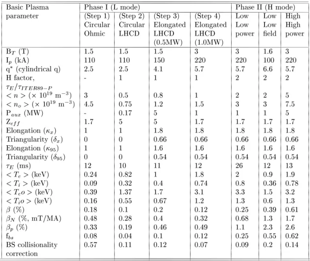
Table2showstypialoperatingparametersin
var-ious steps of phase I and Phase II. Plasma operation
will ommene with irular, pulsedplasma drivenby
ohmi eld for a period of 1 se. This urrent will
besustainedin theseond stepwith thehelp oflower
hybrid wave. About 200 KW power will be used in
thisstep. Thetoroidaleld willbe1.5Tduring these
steps. Step three involves divertor operation at the
same toroidal magneti eld. In the presene of a
irular LHCD driven plasma, the poloidal eld oils
would be brought in a slow time sale of 3-4 se to
produe elongated divertor plasma. In the nal step
ofPhaseI,thetoroidalmagnetieldwillberaisedto
designed 3T and long steady state plasma disharges
wouldbeobtained. Slowswithingofthepoloidaloils
has been simulated and equilibrium is ensured. Full
designparameterswouldthen be attemptedand a
to-talof1MWofauxiliarypowerwouldbeintrodued.
Advane tokomak ongurations will be explored in
phase II of SST-1 operation. In order to improve
valuewith the sameauxiliarypower, onewould
oper-ate at alowertoroidal eld of 1.6T.Further
improve-ment an be obtained in
P and
N
by operating at
lowerurrents. ExperimentationswithVHmode,
non-monotoni q prolesand signiant bootstrapurrent
will be tried. However, these ould be attempted at
the suitable modiations of PFCs for higher power
handling apabilities and enhanement of RF power
systems.
ADITYA Tokamak
ADITYA, a medium size Tokamak, is being
oper-ated foroveradeade. Ithasamajorradiusof0.75m
and minor radius of the plasma is 0.25 m. A
maxi-mumof1.2Ttoroidalmagnetieldisgeneratedwith
thehelp of20toroidaleldoils spaedsymmetrially
in the toroidal diretion. The major subsystems and
parameters of the mahine have been desribed
ear-lier[9℄. ADITYA isregularly being operatedwith the
transformer-onverterpower system. 100mse 80
on edge plasma utuations,turbulene and other
re-latedworkshavebeenonduted. Standarddiagnostis
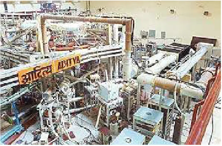
have beenemployed during these measurements. Fig.
8 gives aviewof ADITYA with the auxiliaryheating
systemsattahedtoit.
ADITYA has been upgaded. Vauum system has
been upgraded in terms of more leaning failities.
Somemorediagnostishavebeenintegratedandmade
on-line. Someare in thedesign/fabriationphase. To
inrease the plasma energy ontent during the
dis-harge,auxiliaryheatingsystemshavebeenintegrated.
A20-40MHz,200KWIonCylotronResonane
Heat-ing (ICRH) system has been integrated to ADITYA
vauum vessel. A 28 GHz, 200 KW gyrotron based
eletron ylotron resonane heating (ECRH) system
hasbeensuessfullyommissionedonADITYA
toka-mak. Someneuralnetwork analysis to predit
disrup-tions and density limit on ADITYA have also been
performed.
Figure8. PresentViewofADITYATokamak.
VauumSystemand WallConditioning
It has beenrealised overthe years that lean wall
ondition plays averyimportantrole in obtaining
re-produible disharges. Therefore, the main objetive
hasbeentomaintaingoodvauumandtoperformwall
onditioningtoredueimpuritylevel. Aseriesof
exper-imentshavebeenarriedoutto understandbehaviour
ofquadrupolemassanalyserintokamakADITYA.
Wall leaning tehniques for ADITYA inlude
auto-matedGlowDishargeCleaning(GDC)foramaximum
period of 12 hours, Pulse Disharge Cleaning (PDC),
Eletron CylotronResonane(ECR)disharge
lean-ing. ECRand/orPDC dishargeleaningis ontinued
forfewhoursto24hoursasandwhen required.
Other types of oating, viz. Boronization and
Lithi-newtehniquefor wall onditioningthat is being
reg-ularlyused in othermahines. Initial experiments for
lithium oating in laboratory have been arried out
suessfully. The eet of lithium oatingon the wall
onditionhasbeenobservedintokamaks. Thoughstill
inthephaseofdevelopment,thepotentialadvantageof
thesetehniquesistheirappliationinrealtimeduring
the disharge, making them partiularly suitable for
steadystatedeviesviz. SST-1.
An experiment in tokamak ADITYA with in-situ
lithium onditioning to study eet of lithium
on-ditioning on Aditya Disharges has been performed.
Theaim of lithium onditioningwasto redue
hydro-genreyling, impurity inux and to improve plasma
parameters viz. plasma density, temperature,
on-nement time and MHD ativities. Lithium
ondi-tioning has been done by the evaporation of lithium
in Aditya vauum vessel during disharge leaning.
Partial pressuresof lithium andoxygen aremonitored
withQuadrupoleMassAnalyser. Aninreaseinpartial
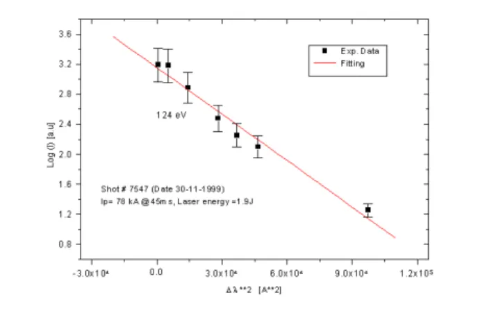
pressureoflithium(100%)hasbeenobservedwhereas
for oxygen, it is redued to 50 %. The density is 1
10 13
m 3
with a at top for 30 milliseond. At
78 KA of plasma urrent, sawteeth was expeted but
notobserved. Preseneoflithium isalsomonitoredby
spetrosopy. An inrease in H-alpha (instead of
re-dution)andredutionin HardX rayswereobserved.
The plasma parameters thus were improved. Plasma
urrent for most of the disharges was more than 97
KAfor100milliseond.
Experimentstostudylithiumoatingonvauumvessel
wall are beingontinued. Solid lithium target probes
have been prepared. These probes are introdued in
aUHV systemand lithium oatingexperiments have
been performed suessfully. More experimentswould
be performed to study the eet of lithium oating.
LithiumoatingonlimiterisalsoproposedinADITYA.
GasFeed System
The gas feed line and related systems for feeding
ofpurehydrogengasto thevauumsystemhavebeen
modied. A series of experiments to study impurity
level for dierent onditions of the gas feed system
havebeenonduted. Fast gas puÆng during plasma
dishargehasbeenarriedoutsuessfully.
EÆient gas fuelling is a prime requirement of
toka-maks. In ADITYA, after obtaining good ultimate
vauum in thesystem, hydrogen gasis introdued for
plasmaprodution. Duringthe disharge, pressurein
thesystemismaintainedat requiredvalue. There are
in veloity prole as angular distribution of inoming
partile, and the slow veloity omponent of gas
par-tiles that an not penetrate into the plasma entre
whih would ultimately oolthe plasma edge. A
on-siderablenumberofrundownpartilesareadsorbedon
thewallsurfaes andlimiters, whih arereleasedfrom
the surfaes during the disharge, beome an
unon-trollable fator in density ontrol. A new method of
gasfuellingintokamakswithmoleularbeaminjetion
hasbeendeveloped. ItseÆieny is50 %. Thebeam
an travel inside plasma for few entimeters thereby
reduing edge ooling. MBI also redues reyling of
thefuelgas.
A moleular beam injetion system for tokamak
ADITYAwithaPiezo-eletrigasinletvalvemodied
inhouse to injet moleularbeamhas been developed.
Thisvalveis mountedonavauum systeminthe
lab-oratory to verify its funtions with various input gas
pressures. Itisobservedthat astheinputgaspressure
inreases, the pressure in the entre of the vessel
in-reases. Butthe pressureremains low near thevessel
wall.
Limiter bias experiment
An understanding of the mehanism of improved
partile/energy onnement in a tokamak is of
paramount importane for the design and operation
of a fusion reator. Several experiments have been
done for this purpose, viz., biased probe, biased
lim-iter, edge ooling, preferential heating of ions at the
edge et. Reently we have arried out alimiter bias
experimentonADITYA.TheADITYAlimiteronsists
of 16 segments of graphite tiles and thus provides an
opportunity to study the role of biasing with a set of
biasingindierentongurations.
Results ofa preliminary experimentof limiter biasing
onADITYAarereported.Oneofthelimitertilesis
bi-asedupto-500Vwithrespettothevessel. Whenthe
limiter urrent drawn exeeds 300 A various
diagnos-tisignalsindiate an improvementof partile/energy
onnement. H
radiationaswellasoatingpotential
utuation(monitored byLangmuirprobes)show
sig-niantredution. Theamplitudeofoatingpotential
reduedby80% at allfrequenies. Beforebiasingthe
limiter frequeny spetrum of the utuation shows a
peakat 10-15 KHz,whihdisappearesduring biasing.
SignalsfromtheentraldetetorofthesoftX-ray
am-eraindiate ariseintemperatureby50-100eVwithin
3-4msoftheappliationofthebias. Asharpderease
upto50%in H
radiationhasbeenobserved.
New diagnosti systems inlude Thomson
satter-ing, Lithium beam, ECE, Bolometer, Soft X-ray et.
Polarimetry is being designed and fabriated to be
testedonADITYA andnallyusedinSST-1. Someof
thesesystemsaredesribedbelow.
Thomson sattering system
The aim is to provide eletron temperature and
density measurementsof ADITYA plasma on shot to
shotbasis. Thesystemis apableto measure eletron
temperature (T
e
=20 eV- 500 eV)and eletron
den-sity(n
e
=5.010 12
-10 13
m 3
)prolesofADITYA
plasma (from z = +22 m. to -14m) with a spatial
resolution of 1mand temporal resolution of 50 nse.
The systemis based on aRubyLaser (10J, 20 nse)
that enters the plasma through an extended bottom
vertialportandexits throughatopvertialport.
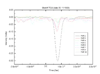
Figure9.ADIYTAThomsonsatteringSignalinpresene
ofplasma.
The90 o
sattered photonsare olletedthrough a
radialportusingaf/5optialsystem(asetofdierent
lenssystems)olletedsatteredspetrumisdispersed
using agratingspetrometer (1200grooves/mm,
reso-lution 8A o
, foal length1m)andexit ofspetrometer
isoupledwithaberbundletodetetors(10hannels,
PMTofRCAmake).
The outputsignals from PMTare ampliedand
digi-tized usingCAMACmodulesand thedataisaquired
and analyzed using a PC loated at the laser ontrol
room.
Wavelength and spetralalibrations of spetrometer,
satteringforstraylightmeasurementsatvarious
pres-suresbyllingthevesselwithN
2 .
Figure10. Eletrontemperaturemeasurementduringa
typialplasmashot.
Spetrosopy
ThePlasmais monitoredwithaGrazingInidene
Monohromator (GIM, 10-600nm)) , a Normal
ini-denespetrometer(NIM,100-300nm)andaVisible
spetrometer(VIS,300-800nm). Alsothere area
num-berofinterferenelterbasedspetrallinemonitorsfor
trakingthespetrallinesfromlowionizationstatesof
OxygenandCarbon. WhenttedwithanICCD
Cam-era at theexit plane, theVISand NIM an apturea
25.0/12.5nmwidespetralregionenteredaroundany
wavelengthatintervalsofabout15milliseonds.
Figure11. VUVspetrafromADITYAplasma.
ThetwoVUV spetrometersusuallyviewthe
mid-planeradialhord but by theuse ofgrazinginidene
mirrors, the line of sight an be shifted towards the
edges also. They are often used as line monitors
wherebyasinglelineismonitoredontinuouslywitha
timeresolutionof)0.1 millise.
Inthevisiblewavelengthregion,anumberof1mmore
fusedsiliabersareusedtogatherlightfromdierent
regionsofinterestintheplasmafaingomponents(in
board and outboard limiters, wallet). Forgathering
suÆientlightfromtheweakBremsstahlungradiation
along a entral hord, a 5 mm dia 'liquid lled light
guide' is set up leading to a PMT detetor equipped
withanarrowband(1 nm) interferenelightlter. All
the visible wavelength diagnostis are alibrated for
absoluteintensitymeasurements.
In the ADITYA disharges of urrent 60 KA and
duration 60 millise , the absolute intensities of H
andCII,CIII,OII,OIIIhavebeenmeasuredand
there-from, the uxes of H,O and C from the SS wall and
theGraphitelimitersbeenquantied. Fromthevisible
BLmeasurementthe Ze in suh dishargeshasbeen
estimated. The rather high value (Ze > 6) suggests
thepossibilityofmedium Zimpurities.
PreseneofFe,Cr,Siintheirlowionizationstateshave
beendetetedintheVUVspetrafromNIM,buttheir
onentrationis yet tobeassessed. The VUV spetra
alsoshowshighlyionizedstatesofOxygenandCarbon
(e.g. OVIIandCV).
ECE Diagnostis
EletronCylotronEmission(ECE)diagnosti
pro-vides very useful measurements of eletron
tempera-ture and its radial prole. An eight hannel E-Band
SuperHeterodyne Radiometer (SHR) is used to
mea-sureECEonADITYAtokamak. Thetemporalandthe
spatialresolutionsoftheSHRare10sand4mm
respetively. Measurements havebeen done with
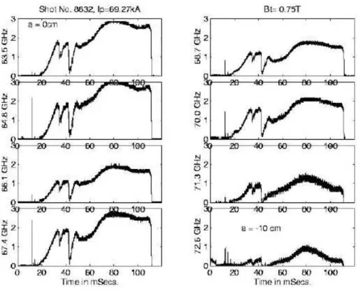
dif-ferenttoroidalmagnetieldsrangingfrom0.75Tto1
T.Initially onlytheoptiallythin,third harmoniwas
measuredwithtoroidal magnetield 0.75T. Typial
signalfor suh ondition onall the eight hannels are
Figure12. EighthannelECEradiometersignal forToroidaleldof0.75T.
With thehelp of density measurementby
interfer-ometer and reetivity estimation from the
measure-mentoftemperaturewithsoftx-raydiagnosti,eorts
arebeingmadetondouttheradialproleofeletron
temperature.
Experimental results
Edge plasma utuation studies are being
ontin-ued. Array of Langmuir probesarebeingdeployed to
measuretheutuations. This turbulentutuationis
deomposedintowaveletsofdierentsales. The
ross-eld transport of utuationamplitude ismodeledby
anonlinearwaveletouplingequation:
Y(k)=L(k)X(k)+ P
i;j
Q(i,j)X(i)X(j)
where, X and Y are wavelet transforms of input and
output signals; i, j and k represent wavelet sales
(a
i = 2
i 1
et.), and L(k) and Q(i,j) are linear and
quadrati ouplingoeÆients respetively. A
formal-ism has been developed for estimating the oupling
oeÆients. Inthisformalism,thenumberof
interat-ing wavelet is small, reduing the degrees of freedom
timation is signiantly smallerthan that required in
Fourier based formalism. The power transfer due to
linear,mixedandquadratiouplingsisrepresentedby
therespetiveoherenies.
The estimates of oupling oeÆients and
oheren-ies for potential utuations in the edge plasma of
ADITYA tokamak reveal interesting features. It is
observed that linear oupling oeÆient and total
o-hereny are lose to 1 when the probe separation is
small. Theyfall withinreasingprobeseparation. The
harateristisalelengthsvaryfrom20mmatalarge
sale (3.5 kHz) to 10 mm at asmall sale (225 kHz).
The sale length an be interpreted as a ross-eld
orrelation length as determined by the linear
ou-pling. The totaloherenyis dominatedbythe linear
ohereny. The quadrati and mixed oherenies are
omparativelysmallbutsigniantatsmallsales. The
quadrati oupling is not widely spread and is strong
only at a few disrete sales. The sign of the power
Figure13. ContoursofonditionalpotentialstrutureswhenC =1.5,dC/dt>0onditionshavebeenappliedonthe
Conditional potential strutures have been
mea-suredintheedgeplasmaofADITYAtokamak[9℄. The
onditionalsamplingtehniqueallowsdeterminationof
the potential struture over a setion of the poloidal
plane from measurements using a radially movable
(poloidal) arrayofLangmuirprobes. Fig.13showsthe
ontours of onditional potential strutures when
=1.5,d
/dt>0onditionshavebeenimposedon
thereferene probe. It is observed that struturesare
elongated in poloidal diretion and seperated on two
sidesofthelastloseduxsurfae. Theradialisolation
isbrokenwhentheamplitudeof thestrutureislarge.
Thedynamialbehaviourofthestruturesuggeststhe
mehanismof `bursty' transportofplasma partilesin
theedge.
Thespatialandtemporalstruturesofmagnetisignal
in the tokamak ADITYA is analysed using reently
developed Singular Value Deomposition (SVD)
teh-nique. Theanalysis tehnique isrst testedwith
sim-ulateddata and thenapplied to ADITYA Mirnov oil
datatodeterminethestrutureofurrentperturbation
asthedisharge progresses. It isobservedthat during
theurrentrisephase,urrentperturbationundergoes
transition from m=5 poloidal mode struture to m=4
and thento m=3modestruture. Atthe timeof
ur-renttermination,m=2modestrutureisobserved.
The understanding of utuation driven anomalous
transport ofpartileand heatis stillofparamount
in-terestin modern fusiondevies. Theapparentlakof
any harateristi time and length sales in the edge
plasmautuationshaspromptedasearhforsale
in-variantproperties. Tothat end, theoating potential
utuationsintheSrape-olayerplasmaofohmially
heated ADITYA tokamak have been analyzed. It is
observedthattheprobabilitydistributionfuntionofa
sumofnrandomutuationsonvergetoaLevy
distri-butionforn<40whereasforlargern,thedistribution
onvergesto aGaussian. The Levy andthe Gaussian
proessesareparadigmsofsuperdiusiveanddiusive
transportproessesrespetively. Thusourobservation
indiates thatthetransport ofsmall saleutuations
takes plae by onvetion, whereas large sales follow
thediusivelaw.
Predition of major disruption
A neural network (NN) tehnique has been used to
preditdisruptionsintokamakADITYA.Atimeseries
preditionmethodhasbeenemployedwherebyaseries
ofpastvaluesofsometimedependentquantityisused
to predit its value in the future. The time varying
observablesused in thework havedierentdiagnosti
signalsfrom 4Mirnov probes, onesoft X-ray monitor
andonehydrogen-alphamonitor. Thepredited
quan-tities are the same observables at some future time.
The neural network has been trained with the past
valuesof thedierentdiagnostisignalsasinputsand
thefuturevaluesofthesamequantitiesastargets. The
trainedneuralnetworkisusedtoforeastinamultistep
sequene. This amounts to a predition several time
stepsearlier. Verygoodpreditionresultsareobtained
upto8msearlierwithlittledistortionofthesignalsand
noappreiable timelag, aapabilitywhihis believed
tobewellsuitedtothetaskofanon-linepreditionof
disruptioninADITYA.
As atual experimental signals are used, ondene
regarding the performane of the neural network on
hardwareimplementationisautomatiallyensured.
Predition of density limit
An attempt has been made to make a predition
of the disruptionboundariesfor the densitylimit
dis-ruption ase using a NN. Using experimental signals
asinput, thenetwork should,in thelong run,be able
to provide information to the real time ontrol
sys-temsaboutthedensity limitatwhih thedishargeis
llikelytodisrupt,sothatthedensityanbekeptbelow
thatlimit. Severaldiagnostisignalsareusedfromthe
ADITYA tokamak and are presentedat seletedtime
instantsto the neural network inputsin order to
pre-dit, at eah of these instants, the density boundary.
Adisruptionthresholdhasbeenestablishedinorderto
examine thepossibilityof using the network asareal
timedisruptionalarm. Formostofthedishargesthis
thresholdisreahedmuhbeforetheatualdisruption.
The NN is also used to make an optimization of the
partiularsetofdiagnostisinordertoobtaintheones
mostruialforpreditingthedensitylimit.
Inuene of eddy-urrent
Inuenes of eddy urrents on the magneti
mea-surementsandtheidentiationproessofplasma
on-trol parametersusingthose measurements,asalso the
optimisation of the magneti diagnostis have been
analysed. This has been onduted with referene to
the SST-1 tokamak. Earlier neural network has been
used on SST-1 where eddies were not inluded. To
the test data set of that study, about 150 additional
dataare nowadded,whihinludedtheeddies. It has
been found that the poloidal and toroidal beta and
the plasma internal indutaneare the worst aeted
by this. The extent to whih the dierent sensorsare
sreened due to the eddy urrents havealso been