Vol-7, Special Issue-Number5-July, 2016, pp993-1002 http://www.bipublication.com
Article view Re
New Method for Data Communication over Power-Line Career
Habib Rasi1 and Maryam Shirzadian Gilan 2
1Depatment of Electrical Engineering,
Shirzaz University of Technology, Shirza, Iran an
2Depatment of Electrical Engineering,
College of Technical and engineering, Kermanshah Branch, Islamic Azad University, Kermanshah, Iran
*Corresponding author: Email: [email protected]
ABSTRACT:
The multifunctional use of power transmission line provides a cost effective method for data and voice signal transmission, besides the power transfer of electric utilities. It utilizes the existing infrastructure of electric utilities and electricity consumers by using the multi access carrier digital communication technology. Broadband over power line is one of the technology uses the existing electric transmission line as a carrier channel for the delivery of Broadband to the consumer. However, the technology meets the drawback that the electric wires might radiate electromagnetic waves at high frequencies. The power-lines are designed to distribute power in an efficient way, hence it is not adapted for communication. The high-speed data transmission power lines require appropriate digital communication techniques that efficiently use the available frequency band. Orthogonal Frequency Division Multiplexing (OFDM), as a type of multicarrier modulation, has become one of the preferred communication schemes to achieve reliable high-rate data transmission. In this paper, designed and presented the broadband over power-line using OFDM method for modulation and multiplexing the signal. Also, the mathematical model which takes into account the coupling equipment and transmission line has been developed. The simulation studies for the combined system and the OFDM has been carried out using MATLAB code.
Keywords: Optimization, Power line, OFDM, Digital communication
[1]INTRODUCTION
One of the most important features of present data communication is its orientation to broadband services. To meet this requirement several media and solutions can be opted viz. Utilizing the existing telephone lines through digital subscriber lines (DSL) or cable distributions via cable modems (CATV), using wireless technologies (WLL, WLAN) or utilizing electrical power lines (PLC). The electrical utility industry is in the process of deregulation and restructuring with the major economic objectives. Power transmission lines, hence are used for multifunctional purposes, besides the electrical power transmission.
By providing electricity consumers access the Internet through their existing electrical lines and domestic cables, this technology possesses potential mass-market scale, without having to invest cabling.
Electrical power lines are usually classified into the high (>l00KV), medium (1-100KV) and low (<1KV) voltage networks, with respectively increasing communication difficulties.
Electrical power is transmitted over high voltage transmission lines, distributed over medium voltages, and used inside buildings at lower voltages. Power line communications can be applied at each stage [2].
The use of existing high-voltage power lines, typically operating at or above 66 Kv, for transmitting data and voice is interesting because it provides electric utilities with an alternative to traditional communication networks.
The lines used for delivery of broadband services are same as those used for transmission of electricity. The development of newer, faster digital processors and sophisticated modulation schemes allowed to send high speed data through existing electric cables along with electrical power frequency currents.
All power line communication systems operate by impressing a modulated carrier signals propagate over transmission lines. A multi-carrier technique viz. Orthogonal Frequency Division Multiplexing (OFDM) is considered as an alternative solution for data communication over power line [3], [4]. [II] POWER- LINE COMMUNICATION Communication over power-line is based on electrical signals, carrying information, propagating over the power-line. The application of the power line communication would be a system where the wiring would impose the main expenses and a radio based system would not be feasible or too expensive. These prerequisites for power line communication system would be met by high voltage or medium voltage power lines because power cables are up to several tens/hundreds of kilometers and approaching even
remote and rural areas. Power system comprises of:
Power generation unit
Transmission lines
Distribution system
Including monitoring and control equipment along with transformer switch gear protection. Transmission and distribution lines are designed for transmission of power from generating station to end user only. However, transmission lines, 66Kv and above are presently employed for audio communication between the operators at two ends of the transmission lines viz. Substation operators, carrier protection schemes and telemetry signal. These signals are modulated before sending on transmission lines in the frequency range of 100 KHz – 500 KHz for overhead transmission lines and 10 KHz – 100 KHz for underground cables. Such conventional modulated communication system over power line functions satisfactorily during normal operation of power system. However, during transient conditions when a fault occurs on the transmission lines, power frequency harmonics up to 100 KHz frequency are generated and distributed to the communication system [5]. It is, therefore required same methodology that the communication shall not be disturbed during transient and emergencies for the safe operation of the power system. Since the power wiring system was originally intended for transmission of AC power, the power wire circuits have only a limited ability to carry higher frequencies.
Power lines are unshielded and will act as antennas for the signals they carry, and have the potential to interfere with shortwave radio communications. In such a case, a novel method using OFDM for data communication over power-line is presented. OFDM modulation, allows to mitigate interference with radio services by removing specific frequencies used.
cover long distances. Only a fraction of the capacity of a fiber optic network in parallel to the high voltage network, for signaling purposes, is currently used. On the other hand, power lines provide spur and discontinuity to the communication signal. The attenuation in the cable at frequencies of interest to communications is usually very large because of large capacitance [5].
[IV] POWER-LINE COMMUNICATION
CHANNEL
In this section, the power-line as a communication channel is discussed. A communication channel is defined as a physical path between two communication nodes on which the communication signal is propagated. Here, I have mentioned basic channel model along with the coupling methods.
4.1. Channel mode
Figure (1) below shows a digital communication system using the power-line as a communication channel. The transmitter is shown to the left and the receiver to the right. Important parameters of the communication system are the output impedance, Zt, of the transmitter and the input
impedance, Zl, of the receiver.
Fig: 1. A digital communication system for the power-line channel
A coupling circuit is used to connect the communication system to the power-line. The purpose of the coupling circuits is twofold: Firstly, it prevents the damaging 50 Hz signal, used for power distribution, to enter the equipment.
Secondly, it certifies that the major part of the received/transmitted signal is within the frequency
band used for communication. This increases the dynamic range of the receiver and makes sure the transmitter introduces no interfering signals on the channel [6].
[V] COUPLING METHODS
Power transmission line operates at high voltage whereas communication equipment functions at volt to millivolts. It is therefore necessary to protect the communication equipment from high voltage transmission line. These equipments are coupled to the transmission line through coupling capacitor or capacitive voltage transformer (CVT) [7].
In order that the communication signal is transmitted in the desired direction, a wave trap is connected towards the substation bus side.
There are two schemes for coupling the equipment to the transmission line:
(i) Phase to Ground coupling (ii) Phase to Phase coupling 5.1. Phase to Ground coupling
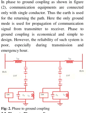
In phase to ground coupling as shown in figure (2), communication equipments are connected only with single conductor. Thus the earth is used for the returning the path. Here the only ground mode is used for propagation of communication signal from transmitter to receiver. Phase to ground coupling is economical and simple to design. However, the reliability of such system is poor, especially during transmission and emergency hour.
Fig: 2. Phase to ground coupling
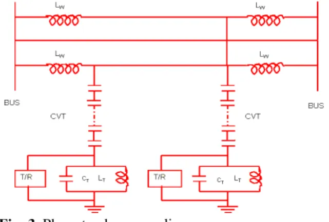
In phase to phase coupling, the conductors of the two phases are used for coupling the communication equipments as shown in figure [3]. Here the signals are fed to transmission lines in differential mode and outer conductors of the phases are generally used for enhancing the reliability though the coupling equipment in the scheme is doubled. Thus, the cost of such coupling scheme is higher to phase to ground coupling.
Fig: 3 .Phase to phase coupling
[VI]DIGITAL COMMUNICATION
Digital communication refers to the transmission of digital data. The data could be transmitted to originate from any source of information. Therefore, the objective of the digital communication system is to communicate digital information, i.e. a sequence of binary information digits over a channel at as high bit rates as possible.
This is in contrast to analog communications. While analog communications use a continuously varying signal, a digital transmission can be broken down into discrete messages. Transmitting data in discrete messages allow for greater signal processing capability so that errors caused by random processes can be detected and corrected. Alternatively, an analog source output can be converted into a digital form and the message can be transmitted via digital modulation [8]. The most important reason is that signal fidelity is better controlled through digital transmission than analog transmission.
The term digital communication covers a broad area of communication techniques including digital transmission and digital radio. Digital transmission involves transmission of digital pulses from a digital source or transmission of analog signals after converting these into digital pulses from analog sources. Digital radio involves the transmission of digitally modulated analog carriers between two or more points in a communication system [9].
Digital transmission system requires a physical channel between the transmitter and receiver, such as a metallic wire pair or a coaxial cable. Digital radio system, the transmission medium could be free space or a physical channel such as optical fiber cable.
[VII] OBJECTIVES OF THE STUDY
The objective of this research is to examine the systematic model for the power-line using a small set of parameters. This model is applied for a high voltage power line. This project is oriented to the application of OFDM to the power-line carrier. In brief, the objectives of the present dissertation are: 1- Design the OFDM scheme for multifunctional power transmission line.
2- Effect of line length on the attenuation of broadband channel.
3- Effect of frequency on characteristic impedance.
[VIII] MODULATION METHOD FOR
Modulation [9], [10] is the process of varying some characteristic of a periodic wave with an external high frequency signal. It is utilized to send an information bearing signal over long distances. These high frequency carrier signals can be transmitted over the transmitted lines or air, and are capable of traveling long distances. The carrier signal can be an electrical current, a radio or microwave frequency or light. The process of extracting the information at the receiving end is called demodulation.
The characteristics (amplitude, frequency, or phase) of the carrier signal are varied in accordance with the information bearing signal. This information bearing signal is also known as the modulating signal. This modulating signal is a slowly varying signal as opposed to the rapidly varying carrier frequency.
Therefore, there are three basic types of modulation: amplitude modulation (AM) varies the amplitude; frequency modulation (FM) varies the frequency, and phase modulation (PM) varies the angle of the wave.
Carriers are used to transmit multiple channels simultaneously within a wire or fiber. For example, several voices, data and video signals can travel over the same line, each residing in its own carrier vibrating at a different frequency [11]. Instead of sending a separate stream of data in each carrier, multiple carriers can be used for only one channel of data. For example, the widely used Orthogonal Frequency Division Multiplexing (OFDM) method uses numerous carriers (sub carriers) for only one transmitting channel and one stream of data [12], [13].
[IX] SYSTEM MODELING
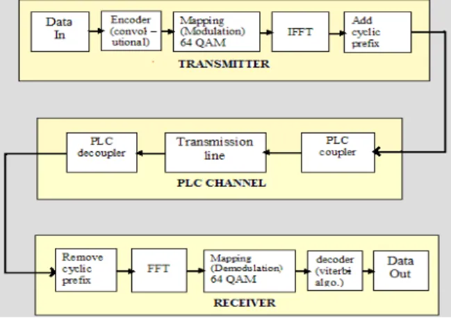
Figure (2) shows a simplified flowchart of the MATLAB simulation code. The simulation model can be divided into three main parts:
1. The transmitting part — it is responsible for encoding and modulation of signals into a form suitable for the transmission channel. After this, a guard period is added, followed by Inverse Fast
Fourier Transform (IFFT) to generate the OFDM signal.
2. The transmission channel (high voltage power line) — this part of the model accounts for the negative influences of the PLC environment on the transmitted signal. Above all, these are the insertion loss and characteristic impedance. Coupler and decoupled are provided at the transmitting and receiving end for proper communication.
3. The receiving part — it is conceptually inverse in comparison with the transmitter. Its main functions are removal of guard period; perform Fast Fourier Transform, demodulation and correction of error information bits.
Fig: 4. System Flowchart
9.1. Transmitting Part
A detailed description about signal generation is given in Chapter-3. The base band signal from legacy networks to provide backend infrastructure support has been generated as a random binary data with a given length as shown in figure (5).
0 1 2 3 4 5 6 7 8
x 10-7 0
0.1 0.2 0.3 0.4 0.5 0.6 0.7 0.8 0.9 1
ti
m
e
(s
e
c
)
generated data
9.2. Encoder
In order to reduce the bit error probability the channel encoder adds redundancy viz. Extra control bits of the bit sequence in a controlled way. When an error appears in the bit stream the extra information is used by the channel decoder, to detect, and possibly correct, the error. The redundancy added is depending on the amount of correction needed, but is also tuned to the characteristics of the channel.
Two coding techniques often used are block codes [4] and convolutional codes [4], [14]. In the present work, convolutional coding is used as an error-control coding.
Convolutional coding is a special case of error-control coding. A convolutional coder is not a memoryless device. Even though it accepts a fixed number of message symbols and produces a fixed number of code symbols, its computations depend not only on the current set of input symbols but on some of the previous input symbols [15].
9.3. Modulation
At this stage, the data are converted to a form of signal that is suitable for propagating over the channel. There are several modulation techniques, described in Chapter-3. In this study, 64-QAM is used as a modulation technique for the mapping of the encoded data. By using this technique, a large number of bits can be sent together. Figure (6) given below, shows the 64-QAM modulated data.
0 1 2 3 4 5 6 7 8
x 10-7 -8
-6
-4
-2
0
Time(sec)
A
m
p
lit
u
d
e
Inphase modulated data
0 1 2 3 4 5 6 7 8
x 10-7 0
2 4 6 8
Time(sec)
A
m
p
lit
u
d
e
Quadrature modulated data
Fig: 6. 64-QAM modulated data
9.4. IFFT
The modulated signal is in the time domain. Therefore, IFFT is used to convert this signal into the time domain. Before performing the IFFT, zeros are added to the modulated signal to achieve over-sampling and to center the spectrum.
An inverse Fast Fourier transform converts the frequency domain data set into samples of the corresponding time domain representation of this data. Specifically, the IFFT is useful for OFDM because it generates samples of a waveform with frequency components satisfying orthogonality conditions [15]. Table (1) shows the OFDM system parameters that are used in programming.
No Parameter Value
1 Carrier Modulation used 64 QAM 2 FFT size 1024 3 Guard interval 1/8
Table: 1. OFDM system parameters used in
programming
9.5. Cyclic Prefix
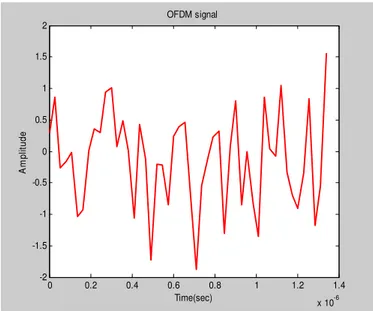
The prefix is added after doing the IFFT just once to the composite OFDM signal. The guard time is cyclically extended for the prefix to a signal. A detailed description about the guard interval is given in Figure (7) given below, shows the OFDM signal.
0 0.2 0.4 0.6 0.8 1 1.2 1.4
x 10-6 -2
-1.5 -1 -0.5 0 0.5 1 1.5 2
Time(sec)
A
m
p
lit
u
d
e
OFDM signal
This signal cannot readily pass through transformers, as their high inductance makes them act as low-pass filters, blocking high-frequency signals; therefore coupling equipment is required at the transmitting end .Therefore, this signal is sent through the power-line using PLC coupler. [X] THE TRANSMISSION CHANNEL
In this thesis, the power-line is used as a transmission channel. Different types of Power line communications use different frequency bands, depending on the signal transmission characteristics of the power wiring used. Since the power wiring system was originally intended for transmission of AC power, the power wire circuits have only a limited ability to carry higher frequencies.
The HV power line is a Multiconductor line and signal propagation is defined by the eigenvector and eigenvalue of a propagation matrix [7]. Impedance and admittance matrices are frequency dependent and can be found using propagation matrix [7] that depends on the line parameters R, L, C.
The total signal attenuation on the PLC channel consists of two parts: coupling losses and line losses [7]. The negative influences of the PLC environment upon the signal transmission depend to the parameters of power-line (core material, cable insulation, cable length, core diameter, the number, position and properties of additional wires tapered from the main path) as well as on the number and properties of points of non homogeneity (instrument panels, PLC signal coupling units, regenerator units). To achieve exact results from the simulation, all these factors must be accepted. But, this acceptance leads to a complicated and complex PLC simulation model. Therefore, for modeling of the PLC transmission channel, a generalized model is used because of its accuracy, easy implementation and understandability [17], [15].
Since in a high-voltage power line system one of the most important limiting factors can be a line mismatch between the transmitter and the receiver station due to the coupling, switching or bypass
devices, therefore a channel characterized by the strong attenuation is considered here. The communication equipment can be coupled to the power line in different ways utilizing different power- line conductors.
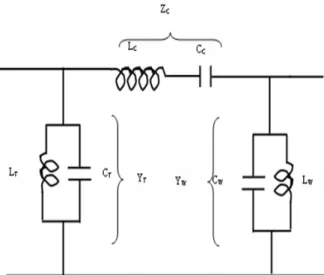
[XI] POWER LINE CARRIER COUPLING EQUIPMENT
The major power line carrier coupling components are shown in figure 8. The inductance of the wave trap LW with capacitance CW and inductance of
tuning coil LT with capacitance CT for two parallel
tuning circuits, while the capacitance CC of the
coupling capacitor with the inductance LC of the
stack tuning coil form a series tuning circuit. All the tuned circuits have a common midband frequency f0. Thus, the coupling equipment at one
end forms a
section band-pass filter.Fig: 8. Simplified equivalent circuit of coupling equipment
Where
T
L ,LW are the inductance of the tuning coil and
wave trap respectively,
T
C , CW are the capacitance of the tuning coil
and wave trap respectively,
T
Y , YW are the admittance of the tuning coil and
wave trap, respectively, and
C
R0 represents the matching termination which is
equal to the source resistance. In [18], it is shown that for LT = 0.5 CC R02
The optimum bandwidth at the half power points under maximally flat conditions can be calculated from f = 4
f02
CC R0
In [7], a mathematical model of a transmission line which takes into account the coupling equipment has been developed. In this, the system is terminated by its characteristic impedance to avoid excessive mismatch losses. Characteristic impedance is the inverse of characteristic admittance.
According to [18], characteristic admittance is defined by using propagation matrix. The propagation matrix has an important property that any function of being a function of only the diagonal propagation matrix1/2, and is defined as
1 2 /
1
Q
Q
Where is the propagation matrix
Q is the eigenvector corresponding to the
eigenvalue
and1 2 / 1 0
YQ Q
Y
Where Y0 is the characteristic admittance.
Therefore, the characteristic impedance is given
as: Z0=Y01
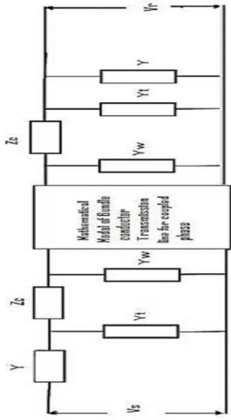
11.1. Effect of coupling equipment
The effect of coupling equipment is to introduce additional losses due to mismatches in the carrier channel. These effects of coupling equipment have been considered by using a
equivalent circuit as shown in figure (9). The coupling capacitor impedance ZC and two shunt admittanceYW and YT corresponds to wave trap and shunt
tuning coil, respectively.
A1= (
ai) and B1= (
bi) are the equivalent towire admittance parameters of the coupled transmission lines.
Fig: 9. Representation of bundle conductor transmission line including coupling equipment
Then the insertion loss As' of the circuit of figure
(9) as described byis given as
'
s
A = ln
R S
V V
= ln(A1 ')
R
Y
+
ln{1ZC(YTY)} + ln{1ZC(YWYS')} -
ln(B1)-ln (YYS)
Where
)} (
1 /{ ) (
'
R YW YT Y ZC Y YT
Y
) 1 /( 1
1 2 '
'
R
S A B A Y
Y
)} (
1 { )'
( W S' C W s'
T
S Y Y Y Z Y Y
Y
Y is the source impedance.
For the sake of simplicity, wave trap and a tuning coil coupling capacitor are assumed as pure inductance and capacitance, respectively.
11.1.1. Receiving Part
removed before packet data is sent to FFT for demodulation.
After the signal has arrived at the receiver, first the prefix is removed to get back the perfectly periodic signal so it can be FFT’d to get back the symbols on each carrier. The received signal is then demodulated followed by performing an FFT.
The demodulated signal is then decoded using Viterbi algorithm [14], [20] as it is a decoding method for the convolution codes.
Finally, the corrected sequence is compared with the original transmitted message and the error rate is calculated.
[XII] CONCLUSION
This paper presents the data transmission by means of PLC technology. Together with the PLC transmission environment, a modulation technique-OFDM is introduced in order to create a complete picture of the PLC transmission path. The basic scheme of the proposed theory is composed of 3 parts: transmitter, transmission channel and receiver. Here, every single component of the transmission path is not considered, but is analyzed as a whole. A power-line model of the complex frequency response up to 1MHz is considered and the model is derived from the physical effects of these elements. The MATLAB results show that the Bit Error Rate is 0.40069.
REFERENCES
1. P. Amirshahi, M. Kavehrad, “On The Channel
Characteristics of Overhead Medium Voltage Power lines for Broadband Communications,” Annual Review of communications, Volume 58, ISBN: 978-1-931695-36-7, December 2005.
2. V. Akarte, N. Punse, A. Dhanorkar, “Power
Line Communication Systems,” International Journal of Innovative Research In Electrical,
Electronics, Instrumentation and control
Engineering Vol. 2, Issue 1, January 2014
3. G. Gong, “ Multicarrier Modulaion and
OFDM”, E & CE 411, Spring 2005.
4. R. C. T. Lee, Mao- Ching Chiu, Jung-Shan
Lin, “Communications Engineering”, IEEE Communications Society, John Wiley & Sons Ltd, 2007.
5. Thomas C. Kutz ,“Broadband over Power
Line: A New Technology for the Future”, The Telecommunications Review 2005.
6. M. Rikaz, N. Landerz, T. Shantharahavan, S
Jeyagopikrishna, “Design Of Domestic Power Line Carrier Communication,” Mar 30, 2014.
7. P.K. Gupta, N.K. Mehta, M. Selot, “Some
Studies on Intrabundle PLCC in Overhead Lines,” Institution of Engineers (I), journal EL, volume 66, 5 April 1986.
8. J. G. Proakis, “Digital Communications”, 2nd
Ed. New York: McGraw-Hill, 1989.
9. Simon Haykin “Communication Systems”, 4th
Edition, John Wiley & Sons, Inc. 2004
10.Kennedy, Davis, “Electronic Communication
system”, Tata McGraw-Hill, 1993.
11.Raju Hormis, Inaki Berenguer, Xiaodong
Wang, “A Simple Baseband Transmission Scheme for Power Line Channels”, IEEE Journal on Selected Areas in Communications, vol. 24, no. 7, july 2006.
12.Louis Litwin, Michael Pugel, “The principles of OFDM”, January 2001.
13.S.B. Weinstein, and P.M. Ebert, “Data
Transmission by Frequency-Division
Multiplexing Using the Discrete Fourier
Transform,” IEEE Transactions on
Communications, 19, 5, pp. 628-634. 2003.
14.Andre Neubauer, Jurgen Freudenberger,
Volker Kuhn, “Coding Theory- Algorithms, Architectures and Applications”, John Wiley & Sons Ltd, 2007.
15.T. L. Singal, “Wireless Communications”, Tata
McGraw-Hill, 2010.
16.A. Peled, and A. Ruiz, “Frequency Domain
Data Transmission Using Reduced
Computational Complexity, Algorithms,” in
Conference on Acoustics, Speech, and Signal Processing (ICASSP’80), pp. 964-967. 2008.
17.H. Meng, S. Chen, Y. L. Guan, C. L. Law, P.
L. So, E. Gunawan, T. T. Lie. “Modeling of Transfer Characteristics for the Broadband Power Line Communication Channel”, IEEE Transactions on Power delivery, vol. 19, no. 3, July 2004.
18.L.M. Wedopohl and E.G. Wasley.
“Propagation of carrier signals in
Homogeneous, Non- homogeneous and mixed Multiconductor system”, Proceeding of IEE, volume 115, January 1968, p179.
19.Halid Hrasnica, Abdelfatteh Haidine, Ralf
Lehnert, “Broadband Powerline