Abstract— This research proposes the automatic visual inspection from three-dimensional characteristics of Hard Disk Drive case tightening process by machine vision system using laser light sectioning. The machine vision camera captures a number of features of HDD perpendicular to a conveyor belt as seen by a laser strip light. The narrow band pass filter (650 nm.) was mouthed in front of lens in order to cut off the unwanted wavelength. After image pre-processing, the laser profiles were calculated the center of gravity to extract the image coordinate. The features used here are the laser strip profile at various locations along the HDD formulating the 3D data. The homography computation was used to transform the image coordinate to the real world distance (in metric system). This scheme can be used to inspect the completeness of screwing process of the HDD which the 2D visual inspection cannot perform on the top view.
Index Terms— Hard disk drive, Metric Vision, 3D inspection
I. INTRODUCTION
ARD disk drives (HDDs) are highly demanded consumer information technology products, e.g. personal computers, laptop and other data storage equipment for cost-effectively storing large-scale information. The inspection process is very important for quality control of HDDs production. HDDs that have failed the final quality and functional testing are sent to a tear down stage. The HDD components that have failed the re-tested process will be sent for scrapping [1]. Many researches in HDD inspection process have been mostly focused on the HDD media surface inspection [1],[2],[3]. However, the final assembly of HDD process is also essential for the mass production such as the screws fastening of HDD housing. Nowadays, manual visual inspection is currently used in the modern Hard Disk assembly process to solve the following problems.
A. Problem statements
1. The screw putting on the HDD housing by the robot is missing. This defect can be checked by 2D automatic visual inspection.
Manuscript received December 29, 2014; revised January 18, 2015. This work was supported in part by Dept. of Instrumentation and Control Engineering, Faculty of Engineering, King Mongkut’s Institute of Technology Ladkrabang, Bangkok, 10520
S. Gulphanich is with department of Instrumentation and Control Engineering, Faculty of Engineering, King Mongkut’s Institute of Technology Ladkrabang, Bangkok, Thailand 10520 (corresponding author e-mail: [email protected]).
N. Nunak is with the King Mongkut’s Institute of Technology Ladkrabang, Faculty of Engineering, Ladkrabang, Bangkok, 10520 Thailand (e-mail: [email protected]).
T.Suesut is with department of Instrumentation and Control Engineering, Faculty of Engineering, King Mongkut’s Institute of Technology Ladkrabang, Bangkok, Thailand 10520 (e-mail: [email protected]).
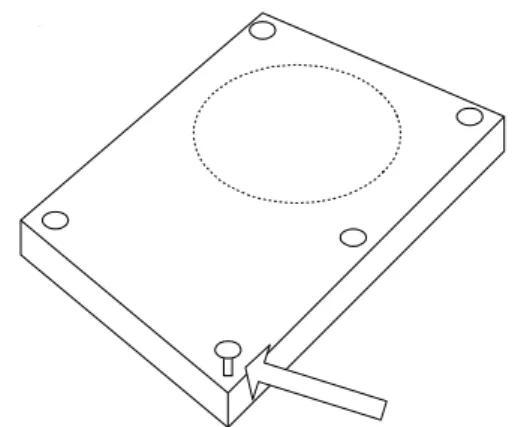
2. The screw has already put on the HDD housing but it is not complete as shown in figure 1. This defect needs to check the tighten screw on HDD assembly by 3D inspection.
This paper shows a feasible design to automate the visual inspection for the completeness of the HDD screwing process based on 3D inspection using Laser Light Sectioning which the 2D visual inspection cannot perform on the top view.
Fig. 1. The incomplete screwing process on the HDD housing
The aim of this paper is to improve the accuracy of measuring the size of the hard drive, such as width, length and checking the tighten screw on HDD assembly by vision system (Metric Vision) in real-time. Moreover, this work can be guided to development of an automated inspection system for the HDD manufacturing as well as other industries.
II. RELATED WORKS
Two-dimensional (2D) computer vision has been dedicated to the development of automated visual inspection systems. However, these systems have had limited success primarily due to the variability in the appearance of the components and their surroundings. The electronic components usually have varying colors, textures, and shapes, which may result in low contrast gray-scale imaging. They have been many techniques developed to enhance certain features of the components being inspected. Even though many component types may be imaged and detected with these techniques, intensity image information obtained from a 2D sensor is not always sufficient to correctly determine the actual condition of the components under inspection; this is particularly true for real-time quality monitoring processes. Therefore, more sophisticated methods or a tool that provides an additional dimension of measurement should be seriously considered.
3D Inspection for HDD Production Process
using Laser Light Sectioning
S.Gulphanich, N. Nunak, and T.Suesut
H
Proceedings of the International MultiConference of Engineers and Computer Scientists 2015 Vol I, IMECS 2015, March 18 - 20, 2015, Hong Kong
ISBN: 978-988-19253-2-9
ISSN: 2078-0958 (Print); ISSN: 2078-0966 (Online)
E. Guerra et al, [4] have designed a monitoring system for three-dimensional integrated circuit manufacturing process on the surface (Surface Mount Technology) to check the original two-dimensional system can be good for validation to the number of text and code on the device. The two-dimensional system cannot distinguish disorders dimensional height. Their research aims to design a 3D scanning laser beam to capture the height dimension. The conversion of images from three dimensions to two dimensions by the intensity of the two-dimensional image has been performed using a histocompatibility cate to distinguish abnormal circuits. This study did not measure up in any unit of measurement.
Peter Schalk and Paul O’Leary [5] bring a laser beam to cut through to the measurement and analysis of cross-sectional diameter steel pipe manufacturing process to determine the quality of production by moving through the process of hot-rolled steel pipes. The problem is that the diameter of the pipe is not a pipe-shaped, not round and does not meet this metric to measure the radius of the cylinder from the estimation of the circumference and validity of the pipe from the deviation of the center. Resolution of the measurement is 1 mm. estimation using least squares method of splitting a single value (Singular Value Decomposition) and calibrated using actual size by the homography transformation.
In various applications, the need to monitor and measure in three dimensions (length, width, height) presented a method for measuring the size of the fruits and vegetables that are symmetrical shapes [6]. The previous work for measuring the size of fish [7] and the symmetrical objects [8] using the laser light sectioning technique were developed.
III. PRINCIPLE OF THE OPERATION
A. Laser light sectioning system
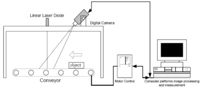
The prototype 3D inspection system consists of a red line laser module 650 nm of wavelength 16 mW 3VDC providing a structured light along the sample perpendicular to the conveyer.
Fig. 2. The prototype of 3D inspection system
The machine vision camera from Basler model SCA 1000 (color 1000x750 pixels) was used to capture the image of projected laser on the HDD housing. The conveyor system consists of 24VDC motor with the belt speed controller. The prototype inspection system has shown in Figure 2. The idea of laser light sectioning can be explained
by Figure 3. and the real experiment with the HDD housing shows in Figure 4.
Fig. 3. The laser light sectioning technique
Fig. 4. The red line laser light on HDD housing
B. Image processing
The image processing was performed using MATLAB and BCAM driver to acquired image from Basler machine vision camera.
Start
Acquire Image
Morphological process
Segmentation
Profiles extraction and Transform to the
measurement coordinate
Reconstruction the 3D surface of HDD housing
End
Fig. 5. The image processing flow chart Proceedings of the International MultiConference of Engineers and Computer Scientists 2015 Vol I, IMECS 2015, March 18 - 20, 2015, Hong Kong
ISBN: 978-988-19253-2-9
ISSN: 2078-0958 (Print); ISSN: 2078-0966 (Online)
The morphological process was used to enhance the image before segmentation process such as image threshold and clear border. The profile extraction was calculated by the principle of center of gravity or first moment [5]. The captured images of laser profiles were transformed to the cross section coordinate for each image frame. The homography transformation can be transformed the image coordinate (a number of pixel) to the measuring coordinate (SI unit). All of cross section profiles will be combined to reconstruct the three dimension image. The highest point and the lowest point on the top of HDD housing can be identified the defect of screw fastening.
C. Metric vision
The planar metrology is the metric vision method to measure the geometry on plane [5]. We must know the real world data being the reference coordinate. In two dimensions, the homography matrix maps the homogeneous point from the homogeneous coordinate as follows. A point in the plane is defined in homogeneous coordinates as
x p y w (1)
In two dimensions, the homography projection H of p to a point p’ on another plane can be formulated as
p’= Hp (2)
' ' ' ' x p y w (3)
where p’ and p are the homogeneous coordinates of the corresponding points p (pixel coordinates) and p’ (real -world), and H is a homography matrix as,
w
y
x
h
h
h
h
h
h
h
h
h
w
y
x
33 32 31 23 22 21 13 12 11 (4)One of the nine parameters with in H can be interpreted as scaling. The remaining eight entries can be determined by using 4 points given in the two planes. A linear algorithm can be derived by expanding equation (4) for a given point correspondence and normalizing with respect to the homogeneous component to yield,
' 11 12 13 ' 21 22 23
31 32 33 31 32 33
,
i i i i
i i
i i i i
h x
h y
h
h x
h y
h
x
y
h x
h y
h
h x
h y
h
(5)In this case, the point correspondences are assumed to be image coordinates, hence homogeneous component wi = w’i = 1 then the homography matrix can be rewritten as
follows: 0 0 0 0 0 0 0 0 0 1 0 0 0 1 0 0 0 0 0 0 1 0 0 0 1 33 32 31 23 22 21 13 12 11 4 4 4 4 4 4 4 1 1 1 1 1 1 1 4 4 4 4 4 4 4 1 1 1 1 1 1 1 h h h h h h h h h y y y x y y x y y y x y y x x y x x x y x x y x x x y x (6)
The solution of the homography matrix can be determined by a linear equation system. Singular value decomposition (SVD) is a least square estimation that can be applied on this matrix to find the non-trivial solutions of the homography. Then the real world coordinate can be calculated using the multiplication of matrix H and p.
IV. EXPERIMENT RESULTS
The area of 3D surface getting from the cross section can be used to classify size of the hard drive (3.5-inch or 5.5-inch). The error from the screwing robot can be checked by measuring the height of screw. The experiment results in this paper were performed in the laboratory. The HDD size 3.5-inch and 5.5-inch from Hitachi Global Storage Company were done by removing the screw on the top of HDD in order to simulate the defect sample.
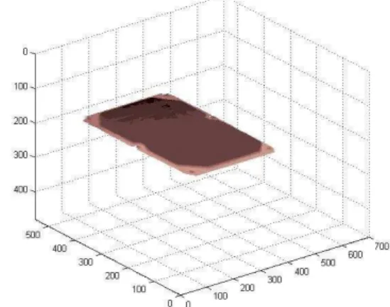
Fig. 6. The 3D image result of HDD housing without defect
Fig. 7. The 3D image result of HDD housing with defect Proceedings of the International MultiConference of Engineers and Computer Scientists 2015 Vol I,
IMECS 2015, March 18 - 20, 2015, Hong Kong
ISBN: 978-988-19253-2-9
ISSN: 2078-0958 (Print); ISSN: 2078-0966 (Online)
The 3D image results are illustrated in figure 6, and 7. According to figure 6, the 3D surface image is complete. There is not found the error or the missing part of the screw. In figure 7, the screw on the corner of HDD is missing.
V. CONCLUSION
This paper presents a 3D object measurement and inspection from the camera which is called Metric Vision. This technique based on laser light sectioning can be applied to measure the size and volume of the object. And converting the image data into three-dimensional coordinate system based on the Planar Metrology and theory to find the distance between two planes adapted to the size, width, length and height of the object. The aim of this paper is to improve the accuracy of measuring the size of the hard drive, such as width, length and checking the tighten screw on HDD assembly by vision system in real-time. Moreover, this work can be guided to development of an automated inspection system for the HDD manufacturing as well as other industries.
REFERENCES
[1] Zhi Sheng Chow, Melanie Po-Leen Ooi , Ye Chow Kuang, and Serge Demidenko “Automated Visual Inspection System for Mass Production of Hard Disk Drive Mediak”, Procedia Engineering, Volume 41, Pages 450–457, 2012.
[2] L. Hepplewhite, T.J. Stonham, and R.J. Glover, “Automated Visual Inspection of Magnetic Disk Media,” in ICECS ‘96, Rodos, Greece, pp. 732-735, 1996
[3] T. Shimakura , Y. Takahashi, M. Sugaya, T. Ohnishi, M. Hasegawa, and H. Ohta “Mirror electron microscope for inspecting nanometer-sized defects in magnetic media”,
Microelectronic Engineering, Vol. 85 pp 1811–1814, 2008. [4] E.Guerra, J.R. Villalobos “A three-dimensional automated
visual inspection system for SMT assembly”, Computers and Industrial Engineering , Volume 40, page 175–190, 2001. [5] Peter Schalk, Paul O’Leary, Ronald Ofner and Anton Gfrerrer
“Measuring and Analyzing Cross-Sectional Profiles of Rotating Objects Using Light Sectioning”, IEEE Transaction on instrumentation and Measurement, Volume 57 No. 10 page 2329–2338, 2008
[6] N.Nunak and T.Suesut, “Measuring geometric mean diameter of fruit and vegetable using computer vision”, PSU-UNS International Conference on Engineering and Environment-ICEE-2007, 2007
[7] N.Nunak and T.Suesut, “Fish Size Measurement by Computer Vision using Laser Light Sectioning”, The 10th Annual Conference of Thai Society of Agricultural Engineering, Thailand, 2009.
[8] Suphan Gulphanich, Maethinee Songthai and Taweepol Suesut, “ Volume Estimation of Symmetrical object using Laser Light Sectioning”, IASTED conference on Modelling, Identification and Control (MIC 2014), Austria 2014.
Proceedings of the International MultiConference of Engineers and Computer Scientists 2015 Vol I, IMECS 2015, March 18 - 20, 2015, Hong Kong
ISBN: 978-988-19253-2-9
ISSN: 2078-0958 (Print); ISSN: 2078-0966 (Online)