ISSN: 2322-2093
Investigation of the Influences of Track Superstructure Parameters on
Ballasted Railway Track Design
Sadeghi, J.1*, Hasheminezhad, A.2, Essmayil Kaboli, M.3
1
Centre of Excellence in Railway Transportation, School of Railway Engineering, Iran University of Science and Technology, Tehran, Iran
2
Research Assistant, School of Railway Engineering, Iran University of Science and Technology, Tehran, Iran
3
M.Sc. Student, School of Railway Engineering, Iran University of Science and Technology, Tehran, Iran
Received: 15 Jan. 2014 Revised: 09 Feb. 2015 Accepted: 10 Feb. 2015
Abstract :The main design criteria of ballasted railway tracks include rail deflections, rail bending stresses, rail wheel contact stresses, sleeper bending moments and ballast sleeper contact pressures. Various criteria have been defined for the design of ballasted railway tracks due to the various mechanical properties of track components and their complex interaction. Therefore, the railway track design is a difficult and time-consuming process. These complications highlight the need to focus attention on the necessity of a thorough investigation into the effect of the track and rolling stock parameters on the design criteria. In an attempt to overcome this problem, a sensitivity analysis of the main railway track design criteria was conducted in this study. Consequently, the roles of track and rolling stock parameters (including track modulus, sleeper spacing, train speed and axle load) in the design of railway track were investigated for various track design criteria. The research findings provide new and practical suggestions in the analysis and design of ballasted railway tracks.
Keywords: Ballasted Railway Track, Design Approach, Sensitivity Analysis, Track Superstructure Components
INTRODUCTION
Railway is a means of smooth and safe transpiration of passengers and goods. Track structures are supposed to sustain the lateral, longitudinal and vertical loads as considered in the design. Steel rails, rail fasteners, timber, steel or concrete sleepers, granular ballast, sub-ballast, and subgrade materials are the main components of a ballasted railway track (Sadeghi, 2012). Due to the wide range of mechanical characteristics of the track complements as well as their complex interaction, there is a lack of a comprehensive and precise understanding of the mechanical behaviour
Corresponding author E-mail: [email protected]
and the pressure transferred to the supporting layers underneath the track (Esveld, 2001). Thus, a deeper understanding of the track operating conditions and a more precise analytical and mechanistic approach is needed to make more accurate and appropriate assumptions in the design process. Moreover, a thorough identification and simplification of the current procedure of ballasted railway track design seems necessary. Herein, a sensitivity analysis of design criteria was performed to achieve a desirable design process and a profound understanding of the behaviours of ballasted railway tracks components. Similarly, the main design criteria of ballasted railway tracks have been presented and their affecting factors have been identified.
BALLASTED RAILWAY TRACKS DESIGN PROCEDURE
Despite the minor differences in the design methods of ballasted railway tracks, one basic approach is followed in almost all available codes. Due to the availability of a great variety of structural elements of a track system, the railway standards consider each track component as a single structural unit and suggest independent design of each component. Subsequently, such an approach includes the interaction between track components by defining suitable boundary conditions and load transfer patterns (Sadeghi, 2008). Therefore, design criteria for different components of ballasted railway tracks are developed independently. Rail bending stress, rail deflection along vertical direction and the contact stress between wheel and rail are considered as the criteria for rail design; load on the rail seat, the contact pressure between the sleepers and the ballast layer, and the sleeper bending stress are considered as the criteria for the sleeper design; and the least required depth is regarded as the main criterion for the
ballast and sub-ballast layers design procedure (Sadeghi, 2008; Gu and Choi, 2013). Design procedure of ballasted railway tracks is generally based on allowable stresses. Thus, internal forces in railway components are calculated and compared with the allowable amounts specified by the standards. Several important criteria that have been defined for each component of the railway track are discussed below.
Current practices in the calculation of rail bending moments and vertical deflections are mainly based on the theory
of “beam on elastic foundation model”
(Greisen et al., 2009). This model was proposed for the first time by Winkler (1867) and thereafter developed by Zimmerman (1888). The basic assumption in the Winkler model is that the deflection of rail at any point is proportional to the supporting pressure under the rail. Acknowledging the Winkler theory of beam on elastic foundation, bending moment (bending stress) and vertical deflection of rail were calculated and compared with the allowable values. Accordingly, the following equations were developed to calculate the rail bending moment and rail deflections:
1 4
0 1 2
n xi xii i
i P
M x e cos x sin x
i , , ,... , n
(1)
x x , y M x , y I
(2)
1 2
0 1 2
n xi xixi xi
i P
y x e cos sin
u i , , ,... , n
(3)
where y(x) and M(x): are the vertical deflection and the bending moment of the
rail at the distance “x” from the load point,
0 254
u .
EI (4)
where u: is the track modulus in N/mm2, E: is the rail modulus of elasticity in N/mm2 and I: is the rail moment of inertia in m4.
Recognition of rail-wheel interactions remains an interesting area of research. However, considering the complexity of this concept and its uncertainties, some authors (Van Dyk, 2014; Sadeghi, 2012) have proposed simplified solutions in railway track design. Eqs. (5) and (6) were applied to calculate the contact stress between the wheel and the rail and the maximum shear stress.
3
10 43 4
mean . Q
r (5)
0 3
min . mean (6)
where Q: is the static wheel load in kN and
r: is the wheel radius in mm.
The longitudinal stress in rail was obtained using Eq. (7), as follows:
L t d a g c
g
t d a c
L
F
F F F F
A A A A A
(7)
where t, d, a, g, c: are the longitudinal stresses due to temperature changes, aerodynamic resistance, acceleration, gradient, and curves, respectively. These values are obtained using the following equations (Sadeghi, 2008).
2
t d
a g
c
F E .A. . t , F C .V
F M . .q , F p.i
k F
R
(8)
where Ft, Fd, Fa, Fg, Fc: are the longitudinal forces due to temperature changes, aerodynamic resistance, acceleration, gradient, and curves,
respectively. The detailed parameters of Eqs. (7) and (8) have been discussed in (Sadeghi, 2008).
The current practices in the analysis and design of sleepers comprise of three steps: i) estimation of vertical rail seat load, ii) assuming a stress distribution pattern under the sleeper, and iii) applying vertical static equilibrium to a structural model of the sleeper (Kerr, 2003). Vertical wheel load is transferred through the rail and distributed on certain numbers of sleepers, due to rail continuity; this process is generally referred to as vertical rail seat load. The exact magnitude of the load applied to each rail seat depends upon several parameters, including the rail weight, sleeper spacing, track modulus per rail, the amount of play between the rail and sleeper, and the amount of play between the sleeper and ballast (Powrie and Clayton, 2007). As vertical loads on railway track have significant effects on the ultimate design, results of each track components and vertical load on the rail seat have important effects on the sleeper design process (Plenge and Lammering, 2003). Various equations have been proposed for rail seat loads. Based on the theory of continuous beam on an elastic foundation, Eq. (9) is applied to calculate the vertical component of the load on the rail seat, as follows.
1
r max
q s.u. y .F (9)
where s: is the sleeper spacing in mm, u: is the track modulus in N/mm2, ymax: is the maximum vertical deflection in mm, and
F1: is the track support variation safety factor.
2
r
a
q
P .F
B .L (10)
where B: is sleeper width in m, L: is sleeper effective length in m and F2: is a factor accounting for adjacent wheels interactions.
Once the sleeper loading pattern is determined, the sleeper can be analysed. Another important design criterion is the bending stresses due to the wheel load. Calculation of sleeper bending stress is required to determine the values of their established bending moments. Values of bending moments are usually calculated in three cross-sections along the sleepers’ length (two at rail seats and at the central part of the sleeper). Eqs. (11) and (12) can be used to calculate the bending moments on the rail seat point and at the centre of the sleepers, respectively.
8 r r l g
M q (11)
2 1
2 4 4
c r r
g g l
M q q (12)
where g: is the distance between the centre of the rails in mm. Consequently, the bending stresses at the rail-seat positions and at the middle section of the sleepers can be calculated by the Eqs. (13) and (14).
2 3 3 4 10 r r l g q .B .t (13)
2 3 2 1 3 2 10 c r g q .B .t (14)
where t: is the thickness of timber sleeper in mm.
The sizes of the aggregates in the ballast and sub-ballast layers have been proposed in the majority of railway standards or codes of practices. Theoretical, semi-empirical and empirical methods are used to determine the depth of
these layers. Appropriate thickness for ballast and sub-ballast layers is the most important aim in the design of these layers (Prakoso, 2012). Eq (15) is considered as the basis for the calculation of the thickness in the ballast and sub-ballast layers (Talbot, 1919).
4 5 0 17
a min c . P h P (15) Sensitivity Analysis
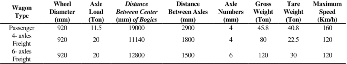
Several assumptions have been made in this paper, including that track structure is ballasted; the rail is a continuous welded rail; track gauge is 1435 mm; the distance between central axes of two rails is 1500 mm; the rail is UIC60; the range of track modulus is 10-40 MPa; type of the sleeper is timber; dimensions of the sleeper are 2400, 2500 and 2600 mm in length, 220, 230, and 240 mm in width, and 115 mm in thickness, range of the sleeper spacing is 500 - 700 mm; allowable bending stress for timber sleeper is 7.6 MPa; effective length for the sleeper is one third of the total sleeper length; and allowable contact pressure between ballast layer and the sleeper is 450 KPa. In this study, three wagons including one passenger wagon and two freight wagons were considered. A schematic view of the selected wagons is presented in Figure 1. Some of the significant characteristics of these wagons are summarized in Table 1.
Passenger wagon
4-axles freight wagon 6-axles freight wagon Fig.1. Schematic view of selected wagons.
Table 1. Main characteristics of selected wagons.
Maximum Speed (Km/h) Tare Weight Ton) ) Gross Weight ( Ton ) Axle Numbers ( mm ) Distance Between Axles ( mm ) Distance Between Center of Bogies ( mm ) Axle Load ( Ton ) Wheel Diameter ( mm ) Wagon Type 160 40.8 45.8 4 2900 19000 11.5 920 Passenger 120 22.5 80 4 1800 11140 20 920 4- axles Freight 120 30 120 6 1500 12800 20 920 6- axles Freight
The effect of different track superstructure parameters on the track responses was investigated in this research. The obtained results are presented in the following figures. Figure 2 represents the effects of track modulus variations on bending stress and vertical deflection of the rail. Figure 2(a) indicates an inverse
and nonlinear relationship between the vertical deflection and the track modulus for values >10 MPa. On the other hand, a linear relationship exists between rail deflections and track axle loads. According to Figure 2(b), there is a considerable increase in the bending stress for track modulus < 10 MPa.
(a) (b)
Fig. 2.Variations of a) rail deflection and b) bending stress as a function of track modulus and wagon speeds. 0
5 10 15 20
0 10 20 30 40 50
R ail V ert ical D ef lect ion ( mm )
Track Modulus (MPa)
P-80 km/h P-100 km/h
P-120 km/h P-160 km/h
F4-80 km/h F4-100 km/h
F4-120 km/h F6-80 km/h
0 50 100 150 200
-10 10 30 50
R ail B end ing Stres s (MP a)
Track Modulus (MPa)
P-80 km/h P-100 km/h
P-120 km/h P-160 km/h
Variations in the contact stress for different wheel radiuses are presented in Figure 3. According to Figure 3, the contact stress between wheel and rail has a linear relationship with the axle load and an inverse relationship with the wheel radius.
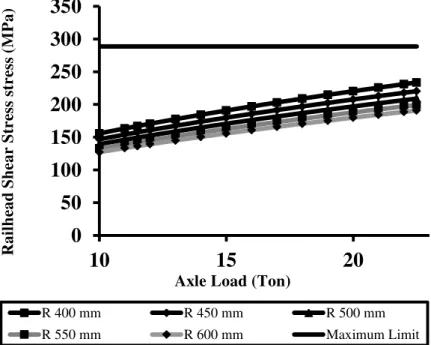
Figure 4 represents the shear stress variations as a function of effective load and wheel radius. According to Figure 4, the rail shear stress was less than the allowable limit, which is in good agreement with the suggestion of AREMA.
Fig. 3. Variations of contact stress spalling with axle load for different wheel radiuses.
Fig. 4. Shear stress variation in railhead for different wheel radiuses. 0
100 200 300 400 500 600 700 800 900
10 15 20
C
on
tact
Stres
s
-
Sp
all
ing
(
MP
a)
Axle Load (ton)
R 400 mm R 450 mm R 500 mm R 550 mm R 600 mm Maximum Limit
0
50
100
150
200
250
300
350
10
15
20
R
ai
lhead
Sh
ear
Str
es
s
st
re
ss
(
MP
a)
Axle Load (Ton)
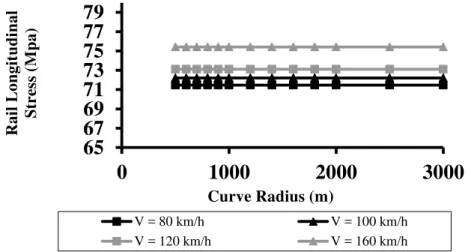
The effects of temperature, speed (wagons) and curve radius on the longitudinal stress are presented in Figures 5 and 6. According to Figure 5, there exists a direct and linear relationship between the longitudinal stress and the rail temperature. At a constant temperature, increasing the speed of rail vehicles slightly affects the rail longitudinal stress. Figure 6 presents the longitudinal stress in UIC60 rail section, indicating suitability of 1000 m for curve radius.
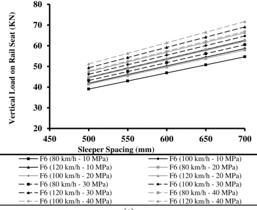
Figure 7 represents the variations in the vertical load applied to the rail seat as a function of sleeper spacing and the
distance between sleepers for the passenger and freight trains. As depicted, some of the graphs are very similar and even overlapped which indicates that different values of speed and track stiffness impose the same amount of vertical load on the rail seat. By selecting an appropriate rail cross-section for the 4-axle freight wagons, a range of 48- 65 kN is expected to be suitable for the vertical rail seat load. These results indicate a larger amount of vertical load on the rail seat for freight wagons in comparison to those for passenger wagons.
Fig. 5. Longitudinal stress variation along the UIC60 rail due to temperature variation for different wagons.
Fig. 6. Longitudinal stress variation along UIC60 rail for different curve radiuses and wagons.
0
20
40
60
80
100
120
140
160
0
20
40
60
R
ai
l
longit
ud
inal
Str
es
s
(MP
a)
Temperature (celsius)
V = 80 km/h V = 100 km/h V = 120 km/h V = 160 km/h Maximum Limit
65
67
69
71
73
75
77
79
0
1000
2000
3000
R
ai
l
L
ongit
ud
inal
Str
es
s
(Mpa)
Curve Radius (m)
(a)
(b) 10
20 30 40 50
450 500 550 600 650 700
V
er
ti
cal
L
oad on
R
ai
l
Seat
(
K
N
)
Sleeper Spacing (mm)
P (80 km/h - 10 MPa) P (100 km/h - 10 MPa) P (120 km/h - 10 MPa) P (160 km/h - 10 MPa) P (80 km/h - 20 MPa) P (100 km/h - 20 MPa) P (120 km/h - 20 MPa) P (160 km/h - 20 MPa) P (80 km/h - 30 MPa) P (100 km/h - 30 MPa)
20 30 40 50 60 70 80
450 500 550 600 650 700
V
er
ti
cal
L
oad on
R
ai
l
Seat
(
K
N
)
Sleeper Spacing (mm)
(c)
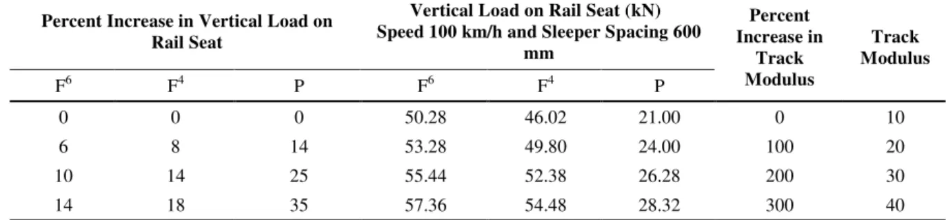
Fig. 7. Variations of vertical load on rail seat for a) passenger train, b) 4- axles freight train, c) 6- axles freight train. Table 2 presents a summary of the
effects of track modulus variations on the magnitude of vertical load transferred onto the rail seat. An increase in the track modulus leads to an increase in the rail seat load.
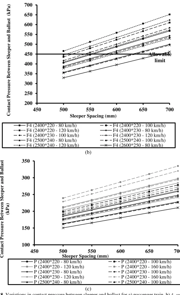
The graphs depicted in Figure 8 illustrate the variations in the contact pressure between timber sleeper and ballast layer. These graphs indicate that by increasing sleeper spacing, the contact pressure between the sleeper and ballast layer also increases. A similar relationship exists between the rolling stock speed and the contact pressure between the sleeper and ballast layer. However, an inverse relationship was noted between the lower face of the sleeper area and the stress intensity between the sleeper and the ballast layer. In terms of the structural design (i.e., when the maximum stress under the sleeper does not exceed the allowable stress value), the results indicate that the passenger wagons (except 4- and 6-axle freights) satisfy the design criteria. Based
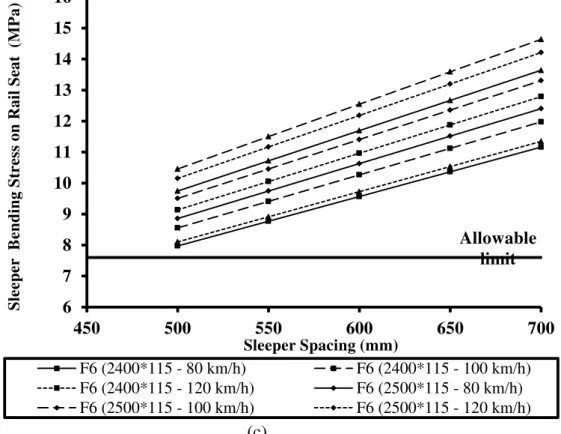
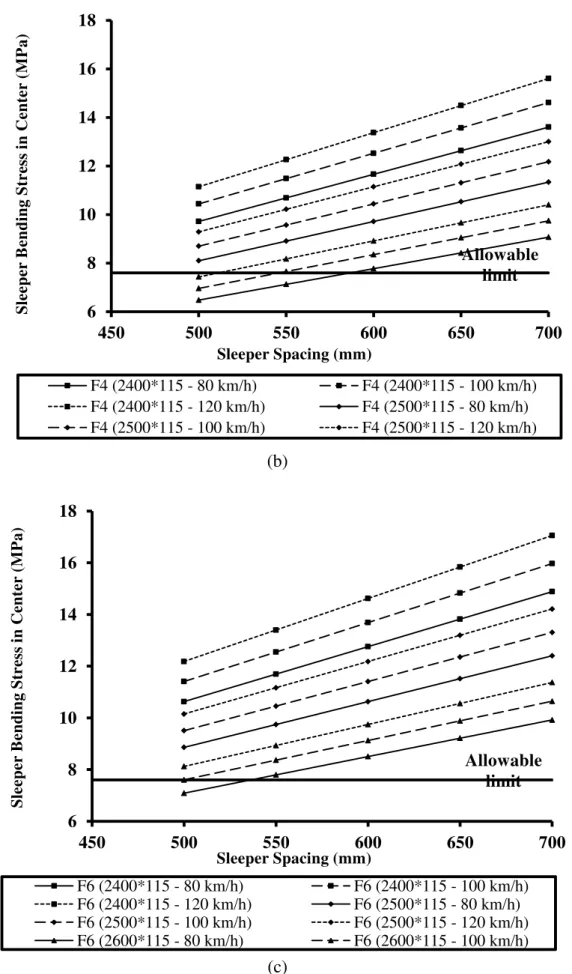
on the graphs presented in Figures 9 and 10, variations in sleeper bending stress occur at two critical cross- sections (rail seat and sleeper centre), which act as a function of rolling stock speed, sleeper length and the spacing between them. Moreover, the spacing between sleepers has a direct relationship with the established bending stress. In case of a constant value for the sleeper length and the spacing, an increase in the speed leads to an increase in the bending stress in the sleeper. On the other hand, if the spacing of the sleeper and the speed of the rolling stock remain unchanged, an increase in sleeper length leads to an increase in the sleeper bending stress in the rail seat along with a decrease in the centre of the sleeper. In addition, the rate of the established bending stress in a sleeper has a direct relationship with the sleeper spacing. These results indicate that timber sleeper is not suitable for railway freight tracks (heavy haul).
20 30 40 50 60 70 80
450 500 550 600 650 700
V
er
ti
cal
L
oad on
R
ai
l
Seat
(
K
N
)
Sleeper Spacing (mm)
Table 2. Effect of track modulus changes on vertical load on rail seat for speed of 100 km/h and sleeper spacing of 600mm (F6, F4 and P represent the 6-axles freight train, 4-axles freight train and passenger train,
respectively).
Track Modulus Percent
Increase in Track Modulus Vertical Load on Rail Seat (kN)
Speed 100 km/h and Sleeper Spacing 600 mm
Percent Increase in Vertical Load on Rail Seat
P F4
F6 P
F4 F6
10 0
21.00 46.02
50.28 0
0 0
20 100
24.00 49.80
53.28 14
8 6
30 200
26.28 52.38
55.44 25
14 10
40 300
28.32 54.48
57.36 35
18 14
(a)
Allowable limit
200 300 400 500 600 700 800
450 500 550 600 650 700
C
ontac
t
P
re
ss
ure
B
et
w
ee
n
Sle
eper
and
B
al
last
(
kP
a)
Sleeper Spacing (mm)
(b)
(c)
Fig. 8. Variations in contact pressure between sleeper and ballast for a) passenger train, b) 4- axles freight train, c) 6- axles freight train.
Allowable limit
200 250 300 350 400 450 500 550 600 650 700
450 500 550 600 650 700
C
ontac
t
P
re
ss
ure
B
et
w
ee
n
Sle
eper
and
B
al
last
(
kP
a)
Sleeper Spacing (mm)
F4 (2400*220 - 80 km/h) F4 (2400*220 - 100 km/h) F4 (2400*220 - 120 km/h) F4 (2400*230 - 80 km/h) F4 (2400*230 - 100 km/h) F4 (2400*230 - 120 km/h) F4 (2500*240 - 80 km/h) F4 (2500*240 - 100 km/h) F4 (2500*240 - 120 km/h) F4 (2600*250 - 80 km/h)
100 150 200 250 300 350
450 500 550 600 650 700
C
ontac
t
P
re
ss
ure
B
et
w
ee
n
Sle
eper
and
B
al
last
(kP
a)
Sleeper Spacing (mm)
(a)
(b) Allowable limit
2
3
4
5
6
7
8
450
500
550
600
650
700
Sle
eper
B
ending
Str
es
s
on R
ai
l
Seat
(
MP
a)
Sleeper Spacing (mm)
P (2400*115 - 80 km/h) P (2400*115 - 100 km/h) P (2400*115 - 120 km/h) P (2400*115 - 160 km/h) P (2500*115 - 80 km/h) P (2500*115 - 100 km/h) P (2500*115 - 120 km/h) P (2500*115 - 160 km/h) P (2600*115 - 80 km/h) P (2600*115 - 100 km/h)
Allowable limit
6 7 8 9 10 11 12 13 14 15
450 500 550 600 650 700
Sle
eper
B
ending
Str
es
s
on R
ai
l
Seat
(
MP
a)
Sleeper Spacing (mm)
(c)
Fig. 9. Variations in the sleeper bending stress on the rail seat under loading for a) passenger train, b) 4- axles freight train, c) 6- axles freight train.
(a)
Allowable limit
6 7 8 9 10 11 12 13 14 15 16
450 500 550 600 650 700
Sle
eper
B
ending
Str
es
s
on R
ai
l
Seat
(
MP
a)
Sleeper Spacing (mm)
F6 (2400*115 - 80 km/h) F6 (2400*115 - 100 km/h) F6 (2400*115 - 120 km/h) F6 (2500*115 - 80 km/h) F6 (2500*115 - 100 km/h) F6 (2500*115 - 120 km/h)
Allowable Limit
2 3 4 5 6 7 8 9
450 500 550 600 650 700
Sle
eper
B
ending
Str
es
s
in C
ent
er
(
MP
a)
Sleeper Spacing (mm)
(b)
(c)
Fig. 10. Variations in the sleeper bending stress at the center of the sleeper under loading for a) passenger train, b) 4- axles freight train, c) 6- axles freight train.
Allowable limit
6 8 10 12 14 16 18
450 500 550 600 650 700
Sle
eper
B
ending
Str
es
s
in C
ent
er
(
MP
a)
Sleeper Spacing (mm)
F4 (2400*115 - 80 km/h) F4 (2400*115 - 100 km/h) F4 (2400*115 - 120 km/h) F4 (2500*115 - 80 km/h) F4 (2500*115 - 100 km/h) F4 (2500*115 - 120 km/h)
Allowable limit
6 8 10 12 14 16 18
450 500 550 600 650 700
Sle
eper
B
ending
Str
es
s
in C
ent
er
(
MP
a)
Sleeper Spacing (mm)
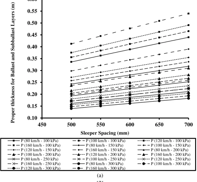
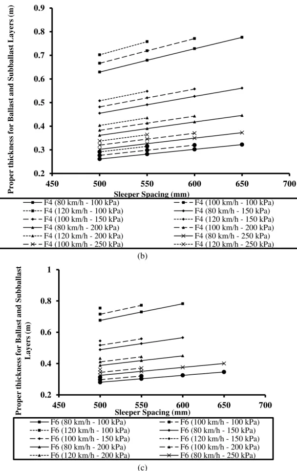
Figure 11 indicates the variations in the thickness of ballast and sub-ballast layers against the sleeper spacing, speed of the rolling stock and the allowable limit of subgrade layer stress. According to these graphs, a linear relationship exists between the required thickness of ballast and sub-ballast layers and the sleeper spacing. In other words, with similar rolling stock characteristics, the greater the sleeper spacing, the higher thickness is required for the ballast and sub-ballast layers. This observation indicates a direct relationship between the thickness of ballast and sub-ballast layers and the sleeper spacing. If the sleeper spacing and rolling stock speed remain constant, increased allowable stress of subgrade layer reduces the need for thicker ballast and sub-ballast layers; and if the sleeper spacing and allowable stress
of subgrade layer remain constant, a larger rolling stock speed leads to an increase in the required thickness of the ballast and sub-ballast layers. In fact, increasing the allowable stress of the subgrade layer reduces the required thickness of the ballast and sub-ballast layers. Notably, these effects have a descending rate. According to Table 3, increasing the subgrade allowable stress leads to a decrease in the required thickness of the ballast and sub-ballast layers. In Table 3, some rows are blank, which indicate that the contact stresses between the sleeper and ballast layer exceed the allowable limits. These limits are in accordance with the considered operating conditions, including axle load, speed, sleeper spacing, track modulus and rail type.
(a) 0.10
0.15 0.20 0.25 0.30 0.35 0.40 0.45 0.50 0.55 0.60
450 500 550 600 650 700
P
roper
t
hic
kn
es
s
for
B
al
last
and
Su
bb
al
last
L
ayer
s
(m
)
Sleeper Spacing (mm)
(b)
(c)
Fig. 11. Changes in the required thickness of the ballast and sub-ballast layers for a) passenger train, b) 4- axles freight train, c) 6- axles freight train.
0.2 0.3 0.4 0.5 0.6 0.7 0.8 0.9
450 500 550 600 650 700
P
roper
t
hic
kn
es
s
for
B
al
last
and
Su
bb
al
last
L
ayer
s
(m
)
Sleeper Spacing (mm)
F4 (80 km/h - 100 kPa) F4 (100 km/h - 100 kPa) F4 (120 km/h - 100 kPa) F4 (80 km/h - 150 kPa) F4 (100 km/h - 150 kPa) F4 (120 km/h - 150 kPa) F4 (80 km/h - 200 kPa) F4 (100 km/h - 200 kPa) F4 (120 km/h - 200 kPa) F4 (80 km/h - 250 kPa) F4 (100 km/h - 250 kPa) F4 (120 km/h - 250 kPa)
0.2 0.4 0.6 0.8 1
450 500 550 600 650 700
P
roper
t
hic
kn
es
s
for
B
al
last
and
Su
bb
al
last
L
ayer
s
(m
)
Sleeper Spacing (mm)
Table 3. Effect of sub grade allowable stress variation on the ballast and sub-ballast layers thickness (sleeper spacing 600mm, UIC 60 rail section).
Subgrade Allowable Stress (kPa) Increase Percent
in Subgrade Allowable Stress The Thickness of Ballast and
Sub-Ballast Layers (m) (for Track Modulus of 10 MPa and Speed of 100
Km/h) Decreased Percent in The
Thickness of The Ballast And Sub-Ballast Layers
P F4
F6 P
F4 F6
100 0
0.41 0.77
***
0 0
***
200 100
0.24 0.44
***
41 43
***
300 200
0.17 0.32
***
59 58
***
CONCLUSIONS
The main design criteria of railway track superstructure were discussed in this paper, including those of rail (i.e., bending stress, vertical deflection and contact stress between the wheel and the rail), sleepers (i.e., vertical load on rail seat, sleeper bending stress and contact pressure between the sleeper and ballast layer), and the ballast and sub-ballast layers (i.e., thickness of the ballast and sub-ballast layers). The effects of railway track superstructure parameters on the design criteria were investigated by conducting sensitivity analyses of the track systems. The analyses were performed for various track parameters characteristics and track operation conditions. The results of sensitivity analysis have been presented in the form of graphs and tables.
Based on the results obtained, a linear relationship exists between the magnitude of bending stress and the train speed. In addition, a non-linear and inverse relationship exists between the vertical deformation and track modulus. By increasing the track modulus, the vertical load applied on the rail also increases. Similarly, increasing the sleeper spacing leads to an increase in the contact pressure between the sleeper and the ballast layer. Timber sleepers are not suitable for heavy haul tracks (freight railway tracks) as they do not meet the design requirements. A linear relationship was observed between the sleeper spacing and the required thickness of the ballast and sub-ballast layers. The more the sleeper spacing, the
greater was the required thickness of the ballast and sub-ballast layers.
REFERENCES
Esveld, C. (2001). Modern railway track, MRT Press, The Netherlands.
Gu, G., and Choi, J. (2013). “The dynamic response of rail support”, Vehicle System Dynamics,
51(6), 798-820.
Greisen, C., Lu, S., Duan, H., Farritor, S., Arnold, R., GeMeiner, B., and Carr, G. (2009).
“Estimation of rail bending stress from
real-time vertical track deflection measurement”, In
2009 Joint Rail Conference, American Society of Mechanical Engineers, pp. 175-182.
Kerr, A.D. (2003). Fundamentals of railway track Engineering, Simmons-Boardman Books, Inc.
Plenge, M., and Lammering, R. (2003). “The
dynamics of railway track and subgrade with
respect to deteriorated sleeper support”, In
System dynamics and long-term behaviour of railway vehicles, track and subgrade, pp. 295-314, Springer Berlin Heidelberg.
Powrie, W., Yang, L.A., and Clayton, C. R. (2007).
“Stress changes in the ground below ballasted railway track during train passage”,
Proceedings of the Institution of Mechanical Engineers, Part F: Journal of Rail and Rapid Transit, 221(2), 247-262.
Prakoso, P.B. (2012). “The basic concepts of modelling railway track systems using
conventional and finite element methods”,
Jurnal Infoteknik, 13(1), 57-65.
Remennikov, A.M., and Kaewunruen, S. (2008).
“A review of loading conditions for railway
track structures due to train and track vertical
interaction”, Structural Control and Health Monitoring, 15(2), 207-234.
Sadeghi, J., and Yoldashkhan, M. (2005).
“Investigation on the accuracy of current practices in analysis of railway track sleepers”,
Sadeghi J. (2008). Fundamentals of analysis and design of railway ballasted track, IUST Publication Survive, Tehran.
Sadeghi J. (2012). “Reliability and safety in railway, Chapter 3 - New advances in design of railway track system”, In-Tech Publication Service, Perpinya, X. (Ed.), ISBN: 978-953-51-0451-3.
Lei, X., and Noda, N. A. (2002). “Analyses of
dynamic response of vehicle and track coupling system with random irregularity of track
vertical profile”, Journal of Sound and Vibration, 258(1), 147-165.
Talbot, A.N. (1919). “Stresses in railroad track,
Report of the Special Committee on Stresses in
Railroad Track”, Proceeding of the AREA, Second Progress Report, 21(1), 645-814. Van Dyk, B.J., Dersch, M.S., Edwards, J.R.,
Ruppert Jr, C.J., and Barkan, C.P. (2014).
“Evaluation of dynamic and impact wheel load factors and their application for design”, In