Mestre em Engenharia Civil
Viability and Applicability of Simplified Models
for the Dynamic Analysis of Ballasted Railway
Tracks
Dissertação para obtenção do Grau de Doutor em
Engenharia Civil
Orientadora: Zuzana Dimitrovová, Professora Auxiliar, Universidade Nova de Lisboa
Júri
Presidente: Prof. Doutor Fernando José Pires Santana Arguentes: Prof. Doutor Geert Degrande
Prof. Doutor José Nuno Varandas da Silva Ferreira Vogais: Prof. Doutor Michaël Steenbergen
Prof. Doutora Zuzana Dimitrovová Prof. Doutor Corneliu Cisma¸siu
Copyright © André Filipe da Silva Rodrigues, Faculdade de Ciências e Tecnologia, Uni-versidade NOVA de Lisboa.
A Faculdade de Ciências e Tecnologia e a Universidade NOVA de Lisboa têm o direito, perpétuo e sem limites geográficos, de arquivar e publicar esta dissertação através de exemplares impressos reproduzidos em papel ou de forma digital, ou por qualquer outro meio conhecido ou que venha a ser inventado, e de a divulgar através de repositórios científicos e de admitir a sua cópia e distribuição com objetivos educacionais ou de inves-tigação, não comerciais, desde que seja dado crédito ao autor e editor.
Este documento foi gerado utilizando o processador (pdf)LATEX, com base no template “unlthesis” [1] desenvolvido no Dep. Informática da FCT-NOVA [2].
all models are wrong; some models are useful.
The work described in this thesis would have not come to fruition without the guidance, help and support of several individuals and institutions to which I am deeply indebted and wish to express my sincere gratitude:
To my supervisor, Professor Zuzana Dimitrovová, for her continued guidance, sharing of knowledge and encouragement, not only over the course of the doctoral program, but since the start of our collaboration in 2007, when she introduced me to the field of railway transportation. She played a fundamental role in my desire to pursue this topic, and my present and future achievements would not have been possible without her.
To the many Professors that accompanied me over my education atFaculdade de Ciên-cias e Tecnologia da Universidade Nova de Lisboa, but in particular to the Professors Manuel Gonçalves da Silva, José Varandas and Corneliu Cismaşiu, which contributed greatly to
my interest in and knowledge of numerical models in Engineering.
To the members of the project SMARTRACK, which provided an opportunity to test the water before diving in to the PhD. Besides the aforementioned Professors Dimitro-vová, Gonçalves da Silva and Varandas, I want to thank Filipe Correia and Ruben Silva for their collaboration and exchange of ideas in that formative period.
ToFundação para a Ciência e a Tecnologiafor their financial support through the PhD grant (SFRH/BD/75375/2010) and the project SMARTRACK (PTDC/EME-PME/101419-/2008).
To my many colleagues and friends at the Department of Civil Engineering, for shar-ing their knowledge and their good humour and for the heated discussions at lunch. Special thanks go to Nuno Deusdado, which helped me get through moments of self doubt with his encouragement and wise advice.
To my friends outside academia, both old and recent, for filling my life with laughter and always sharing different points of view and interests.
To my parents, Vítor and Jacinta, and to my brother Paulo, for their unconditional love and support. They taught me to always strive to be the best version of myself, both with their words and with their actions.
The numerical models of the railway track are fundamental tools for the study of their dynamic behaviour, with implications for the safety and comfort of rail transport and the degradation and need for maintenance of the track. The importance of these models has increased alongside the speed and capacity of the railway vehicles over the last decades. Although the use of three-dimensional finite element models is becoming common practice, simplified models are still relevant, due to their simplicity of implementation and results interpretation, and low computational cost. However, the general validity of these models has not yet been demonstrated in the relevant literature.
The present thesis aims to establish the applicability and viability of such simplified models in the analysis of the dynamic behaviour of the ballasted railway track. The following questions are considered:
1. Are these models able to approximate the real rail displacement due to the passage of rail vehicles, despite their simplicity?
2. If yes, for which situations (i.e., track properties and loading conditions) can they be used reliably?
3. In these situations, is it possible to define adequate parameters for the simplified models based on the track’s geometry and mechanical properties?
To that end, three linear elastic models are implemented: a detailed three-dimen-sional finite element model, a one-dimenthree-dimen-sional beam in discrete supports model, and a one-dimensional beam on elastic foundation model. Transient and steady-state dynamic solutions for a load moving at moderate and high speed are obtained. The vertical dis-placement of the rail is chosen as the reference to measure the equivalence between the models, since it is a common element between all models and is the interface between the load and the track.
The three-dimensional model is validated by comparison with published experimen-tal measurements. Its results cover a representative range of the properties of the ballast and subgrade, and are used as a reference to calibrate the simplified models using genetic algorithms and non-linear programming.
more relevant to the dynamic behaviour of the track, and the simplified models become less reliable.
Following a review of the existing literature, theoretical expressions for the determi-nation of the parameters of the simplified models are proposed. It is concluded that these are suitable for the beam on discrete supports model, but not for the beam on elastic foundation model, whose optimum parameters are less consistent across the different
properties of the track and load speeds.
Os modelos numéricos de vias-férreas são ferramentas essenciais no estudo do seu com-portamento dinâmico, com implicações para a segurança e conforto do transporte ferro-viário e a degradação e manutenção da via. A importância destes modelos tem aumentado juntamente com a velocidade e capacidade de carga dos veículos ferroviários ao longo das últimas décadas.
Embora o uso de modelos de elementos finitos tridimensionais se tenha tornado prác-tica comum, os modelos simplificados têm ainda relevância, devido à sua simplicidade de implementação e interpretação de resultados, além do baixo custo computacional. Con-tudo, a validade geral destes models não foi ainda demonstrada na literatura pertinente. A presente tese tem como objectivo establecer a aplicabilidade e viabilidade dos mo-delos simplificados na análise do comportamento dinâmico da via-férrea balastrada. As questões estudadas são:
1. Estes modelos são capazes de aproximar os deslocamentos reais nos carris devido à passagem de veículos ferroviários, apesar da sua simplicidade?
2. Se sim, em que situações (i.e., que propriedades da via e condições de carregamento) podem ser utilizados com confiança?
3. É possível, nestas situações, definir parâmetros adequados para os modelos simpli-ficados com base nas propriedades geométricas e mecânicas da via?
Para o efeito são implementados três modelos elástico-lineares: um modelo tridi-mensional detalhado de elementos finitos, um modelo biditridi-mensional de viga em apoios discretos e um modelo unidimensional de viga em fundação elástica. São então obtidas soluções dinâmicas transientes e estacionárias para uma carga móvel com velocidade mo-derada e alta. O deslocamento vertical do carril é escolhido como referência para medir a equivalência entre modelos, uma vez que se trata de um elemento comum entre todos eles e serve de interface entre a carga e a via-férrea.
cularmente quando a carga se move a uma velocidade inferior à da propagação das ondas elásticas no solo. Para velocidades elevadas e/ou solos moles, a propagação de ondas elás-ticas torna-se mais relevante para o comportamento dinâmico da via-férrea, e os modelos simplificados tornam-se menos fiáveis.
Após uma revisão da literatura pertinente, são propostas expressões teóricas para determinar os parâmetros dos modelos simplificados. Conclui-se que estas expressões são adequadas para a viga em apoios discretos, mas não para a viga em fundação elástica, cujos parâmetros optimizados são menos consistentes para as diferentes propriedades da via-férrea e velocidades da carga móvel.
List of Figures xix
List of Tables xxvii
List of Symbols xxxv
1 Introduction 1
1.1 Background and motivation to the study . . . 1
1.2 Aim of the research and expected contributions . . . 2
1.3 Summary of the developed work . . . 5
1.4 Thesis outline . . . 8
2 The Ballasted Railway Track 9 2.1 Introduction . . . 9
2.2 Rails . . . 10
2.3 Rail fastening system . . . 12
2.3.1 Baseplate and guide plates . . . 14
2.3.2 Elastic fasteners . . . 14
2.3.3 Rail pads . . . 14
2.3.4 The Vossloh Zw687a EVA rail pad with direct fastening . . . 18
2.4 Sleepers . . . 21
2.5 Ballast . . . 23
2.5.1 Ballast material . . . 25
2.5.2 Particle size distribution of the ballast . . . 27
2.5.3 Geometry of the ballast . . . 27
2.5.4 Elastic properties of the ballast bed . . . 30
2.5.5 Sub-ballast . . . 33
2.5.6 Ballast damping . . . 34
2.6 Subgrade . . . 37
2.7 Other components . . . 40
2.8 Conclusions . . . 41
3.1 Introduction . . . 43
3.2 Geometry of the model . . . 45
3.2.1 Rail . . . 46
3.2.2 Sleepers . . . 46
3.2.3 Ballast layer . . . 48
3.2.4 Subgrade . . . 48
3.2.5 Mesh . . . 49
3.3 Material properties . . . 50
3.4 Convergence study . . . 55
3.4.1 Static analysis . . . 55
3.4.2 Modal analysis . . . 57
3.4.3 Dynamic transient analysis . . . 58
3.5 Boundary conditions . . . 67
3.5.1 Infinite media truncation techniques . . . 68
3.5.2 Local absorbing boundary conditions . . . 69
3.5.2.1 Approximations to the one-way wave equation . . . 71
3.5.2.2 OWWE and viscous boundaries for elastic waves . . . 72
3.5.3 Viscoelastic boundaries . . . 73
3.5.3.1 Bottom boundaries . . . 73
3.5.3.2 Lateral boundaries . . . 75
Static loads in axisymmetric media . . . 75
Wave propagation in axisymmetric media . . . 76
Wave propagation in three-dimensional media . . . 81
3.5.3.3 Rail absorbing boundaries . . . 83
3.5.4 Efficacy of the boundary conditions . . . 84
3.5.4.1 Bottom elastic boundary . . . 85
3.5.4.2 Lateral elastic boundary . . . 87
3.5.4.3 All elastic boundaries . . . 90
3.5.4.4 Absorbing boundary conditions . . . 91
3.5.5 Conclusions on the boundary conditions . . . 94
3.6 Moving loads . . . 95
3.6.1 Convergence study . . . 96
3.6.2 Depth of the subgrade modelled . . . 97
3.6.3 Time discretisation . . . 98
3.6.4 Model length and steady-state solution . . . 99
3.6.5 Conclusions on the moving loads . . . 101
3.7 Validation with experimental results . . . 102
3.8 Conclusions . . . 106
4.2 Beam on elastic foundation . . . 108
4.2.1 Beam on Winkler foundation . . . 108
4.2.2 Beam on Pasternak foundation . . . 109
4.2.3 Other elastic foundation models . . . 110
4.2.4 Timoshenko beam on elastic foundation . . . 112
4.2.5 Experimental values for the track modulus . . . 116
4.2.6 Analytical expressions for the elastic foundation parameters . . . 119
4.2.6.1 Discrete support stiffness . . . 119
4.2.6.2 Substructure stiffness . . . 121
4.2.6.3 Substructure reaction modulus . . . 123
Multiple layers . . . 127
4.2.7 Conclusions on the beam on elastic foundation models . . . 128
4.3 Lumped parameter models . . . 129
4.4 Beam on discrete supports . . . 130
4.4.1 Parameters for the discrete supports . . . 132
4.4.1.1 Ballast stiffness and mass . . . 133
4.4.1.2 Foundation stiffness . . . 135
4.4.1.3 Parameters across the literature . . . 137
4.4.2 Conclusions on the beam on discrete supports models . . . 138
5 Mechanistic expressions for the simplistic models 139 5.1 Introduction . . . 139
5.2 Stiffness . . . 139
5.2.1 Ballast vertical stiffness . . . 140
5.2.2 Subgrade vertical stiffness . . . 144
5.2.3 Ballast and subgrade shear stiffness . . . 144
5.2.3.1 Ballast shear stiffness . . . 145
5.2.3.2 Subgrade shear stiffness . . . 146
5.3 Damping and mass . . . 146
5.3.1 Mass . . . 147
5.3.2 Damping . . . 148
5.3.2.1 Radiation damping . . . 149
5.3.2.2 Material damping . . . 150
5.4 Mechanistic expressions for the elastic foundation models . . . 151
5.4.1 Vertical stiffness and damping . . . 151
5.4.2 Shear stiffness and damping . . . 152
5.4.3 Mass . . . 152
5.5 Parameters for the optimization of the simplistic models . . . 153
5.5.1 Stiffness . . . 154
5.5.2 Damping . . . 155
5.6 Conclusions . . . 156
6 Beam on Elastic Foundation Model 157 6.1 Introduction . . . 157
6.2 Model . . . 158
6.2.1 Beam on Winkler foundation . . . 158
6.2.1.1 Moving load on a beam on Winkler foundation . . . 160
6.2.2 Beam on Pasternak foundation . . . 168
6.2.2.1 Moving load on a beam on Pasternak foundation . . . 170
6.3 Optimization . . . 181
6.3.1 Individual optimization . . . 183
6.3.2 Combined optimization . . . 183
6.3.3 Beam on Winkler foundation . . . 184
6.3.4 Beam on Pasternak foundation . . . 187
6.3.4.1 Static case, individual optimization . . . 188
6.3.4.2 Static case, combined optimization . . . 188
6.3.4.3 Dynamic case, 50 m/s, individual optimization . . . 193
6.3.4.4 Dynamic case, 50 m/s, combined optimization . . . 195
Material damping . . . 199
6.3.4.5 Dynamic case, 100 m/s, individual optimization . . . 201
6.3.4.6 Dynamic case, 100 m/s, combined optimization . . . 202
Material damping . . . 205
6.4 Conclusions . . . 209
7 Beam on Discrete Supports Model 211 7.1 Introduction . . . 211
7.2 Model . . . 212
7.2.1 Rail . . . 213
7.2.2 Masses . . . 213
7.2.3 Spring-dampers . . . 213
7.2.4 Boundary conditions . . . 213
7.2.5 Loads . . . 214
7.3 Optimization . . . 214
7.3.1 Static case, individual optimization . . . 216
7.3.2 Static case, combined optimization . . . 217
7.3.2.1 Reduced subgrade depth . . . 224
7.3.6.1 Material damping . . . 235
7.4 Conclusions . . . 236
8 Validation of the mechanistic expressions 239 8.1 Introduction . . . 239
8.2 Stiffness . . . 239
8.2.1 Ballast vertical stiffness . . . 240
8.2.2 Subgrade vertical stiffness . . . 241
8.2.3 Ballast shear stiffness . . . 244
8.2.4 Subgrade shear stiffness . . . 244
8.2.5 Static vertical displacement . . . 247
8.3 Damping and mass . . . 251
8.3.1 Mass . . . 252
8.3.2 Damping . . . 253
8.3.2.1 Material damping . . . 254
8.3.2.2 Radiation damping . . . 254
8.3.3 Dynamic vertical displacement . . . 255
8.4 Validation with experimental results . . . 258
8.5 Conclusions . . . 259
9 Conclusions and Future Research 261 9.1 Findings . . . 262
1st question . . . 262
2nd question . . . 262
3rd question . . . 263
9.2 Practical Application . . . 264
9.3 Limitations . . . 265
9.4 Future Research . . . 265
Bibliography 267 A Error Measures 289 B The Caughey Absorbing Layer Method 293 C Roots for the solution for a moving load on a beam on elastic foundation 297 D Genetic Algorithm Optimization 301 D.1 Specifications . . . 302
2.1 Traditional ballasted railway track and transmission of the vertical load,
Get-zner Werkstoffe GmbH, 2015. . . 9
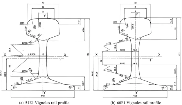
2.2 Vignoles rail profiles for main line applications, EN 13674-1, 2011. Dimen-sions in millimetres. . . 11
2.3 Vossloh’s direct and indirect fastening systems, ThyssenKrupp GfT Gleistech-nik GmbH, 2010. . . 13
2.4 Vossloh W14 direct rail fastening system, Vossloh Fastening Systems GmbH, 2010. . . 13
2.5 Rail pads with respective assemblies, Carmo, 2014. . . 14
2.6 Schematic illustration of static and dynamic load-deflection for a studded rubber rail pad, Nielsen and Oscarsson, 2004. . . 15
2.7 HDPE rail pad stiffness as a function of load frequency, based on Kaewunruen and Remennikov, 2009. . . 15
2.8 Zw687a EVA rail pad; dimensions: 180×158×6 mm3, Knothe, 2013. . . . . 19
2.9 Zw687 EVA static behaviour, adapted from Knothe, 2013. . . 20
2.10 Typical twin-block reinforced sleeper, EN 13230-1, 2009. . . 21
2.11 Typical pre-stressed mono-block sleeper, EN 13230-1, 2009. . . 22
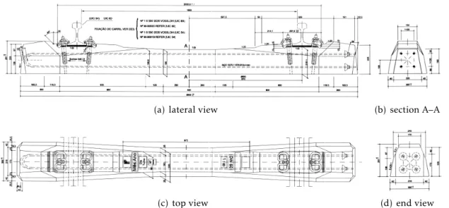
2.12 DW system post-tensioned mono-block concrete sleeper for 54E1 and 60E1 rails, IMV-019, 2000. . . 23
2.13 Ballast bed packed around mono-block concrete sleepers, Wikimedia Com-mons, 2005. . . 23
2.14 Load distribution in the ballast (gradation), Lichtberger, 2005. . . 25
2.15 Schematic representation of skeleton grains, distance grains and filler grains, Lichtberger, 2005. . . 26
2.16 Ballast samples, Wikimedia Commons, 2004, 2009. . . 26
2.17 Ballast gradation curves according to EN 13450, 2003, from Alemu, 2011. . . 28
2.18 A typical cross-section of ballasted track, Selig and Waters, 1994. . . 28
2.19 Load distribution in the ballast (thickness), Lichtberger, 2005. . . 29
2.20 Ballast cross-section for a single-track railway, IT.GER.004, 2004. . . 30
2.21 Histogram of the ballast properties across the consulted literature. . . 32
2.22 Histogram of the sub-ballast properties across the consulted literature. . . . 36
2.24 Histogram of the subgrade properties across the consulted literature. . . 40
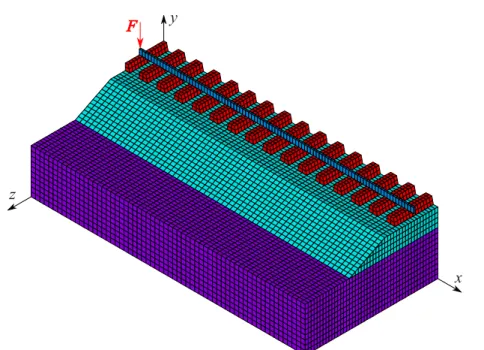
3.1 Three-dimensional FE model of the railway track. . . 45 3.2 BEAM4: 3D elastic beam element, ANSYS Inc., 2009 . . . 46 3.3 SOLID185: 3D homogeneous structural solid element, ANSYS Inc., 2009 . . 46 3.4 Mesh of the three-dimensional FE model of the railway track. . . 49 3.5 Vertical static load applied to the doubly-symmetric FE model. . . 56 3.6 Vertical displacement of the rail as a function of the number of DOFs. . . 56 3.7 First fundamental frequency of the model as a function of the number of DOFs. 58 3.8 First mode of vibration for different meshes (Table 3.3). . . 59
3.9 Propagation of seismic waves, Olivadoti, 2001. . . 59 3.10 Ricker wavelet and respective Fourier transform fortp=ts= 12×10−3s (v= 50
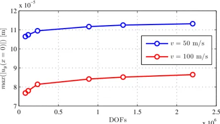
m/s), andFmax= 40 kN. . . 62 3.11 Maximum vertical displacement atx= 0 for both speeds as a function of the
number of DOFs. . . 65 3.12 Relative difference of theL2-norm over time to the last mesh in the rail
dis-placements for both speeds as a function of the number of DOFs. . . 65 3.13 Vertical displacement of the rail atx= 0 for the different meshes. . . 65
3.14 Vertical displacement of the rail at specific time instants for the different
meshes. . . 66 3.15 Amplitude spectrum of the vertical displacement of the rail at x= 0 for the
different meshes. . . 66
3.16 Normalized vertical displacement of the rail atx= 0 for the different values of
the loss factor. . . 67 3.17 Area of influence of a node on a regularly meshed surface. . . 70 3.18 Slice of an axisymmetric cylinder cut at the boundaryr=r1. . . 75
3.19 Spring-damper-mass element for implementation of the radial BCs, Liu et al., 2006. . . 80 3.20 Cross section of the three-dimensional model. . . 84 3.21 Natural modes of vibration of the reference model and the model with
cylin-drical elastic boundaries. . . 92 3.22 Normalized vertical displacement of the rail atx= 0 for the different BCs. . . 94
3.23 Normalized vertical displacement of the rail at x = 0 for the spherical vis-coelastic BCs and the 4th and 5th meshes. . . 94 3.24 Rail vertical displacement at mid-span due to the passage of a moving force
for different number of sub-steps. . . 99 3.25 Amplitude spectrum of the rail vertical displacement at mid-span due to the
passage of a moving force for different number of sub-steps. . . 99
3.26 Normalized vertical displacement of the rail under a moving load for different
3.28 Maximum normalized vertical displacement of the rail under a load moving
at different velocities forEb=Es= 50 MPa. . . 102
3.29 Transition zone, Paixão, 2014 . . . 103
3.30 Alfa Pendular passenger train configuration (in m) and approximate axle loads (in kN), Paixão, 2014 . . . 103
3.31 Vertical displacement of the rail at the S1 section of the Alcácer bypass, Paixão, 2014 . . . 105
4.1 Beam on Winkler elastic foundation, Avramidis and Morfidis, 2006. . . 108
4.2 Beam on elastic Pasternak foundation, Avramidis and Morfidis, 2006. . . 110
4.3 Beam on Kerr elastic foundation, Avramidis and Morfidis, 2006. . . 111
4.4 Modes of vibration for a FE model of a UIC43 rail, Thompson, 1997. . . 113
4.5 Natural frequencies for simply supported Euler-Bernouli and Timoshenko beams (L= 100 m), published in Dimitrovová and Rodrigues, 2010. . . 114
4.6 Critical velocity of the moving load for infinite Euler-Bernouli and Timo-shenko beams. . . 115
4.7 Experimental determination of the track modulus using a single wheel load, Lundgren et al., 1970. . . 116
4.8 Experimental determination of the track modulus using multiple wheel loads, Lundgren et al., 1970. . . 117
4.9 Chart for the determination of the track modulus using a vehicle with two bogies with two wheelsets each, Kerr, 2000. . . 118
4.10 Model of the track as a series of spring layers, adapted from Kerr, 2000. . . . 119
4.11 The Saller assumption, based on Kerr, 2000. . . 121
4.12 Stress-cone load distribution in the ballast, adapted from Cai et al., 1994a, based on Ahlbeck et al., 1975. . . 122
4.13 The Vlasov simplified-continuum model, Teodoru and Muşat, 2010 . . . 124
4.14 Dependence of functionf (y) on the dimensionless parameterγsub=γsubh. . 125
4.15 KsubandKsub,P as a function ofhfor different values ofγsub. . . 126
4.16 Lumped parameter models, adapted from Dong, 1994. . . 129
4.17 Beam on discrete supports models, adapted from Dong, 1994. . . 131
4.18 Beam on discrete supports with sleepers as beams on elastic foundation, Bu-reika and Subačius, 2002. . . 131
4.19 Beam on three-element discrete supports model, based on Zhai et al., 2004. . 132
4.20 Superposition of the stress distribution cones in the longitudinal direction, based on Zhai et al., 2004. . . 133
4.21 Variation of the ballast vertical stiffness as a function of its depth according to Zhai et al., 2004. . . 135
4.23 Variation of the subgrade vertical stiffness as a function of the ballast depth
according to Zhai et al., 2004. . . 136 4.24 Variation of the substructure stiffness as a function of the ballast depth. . . . 137
5.1 Envelope of the vertical stress greater than 10% of its maximum value due to a distributed loading at the surface of the medium, Duncan, 2012. . . 141 5.2 Static vertical stress in the 3D FEM model of the railway track. . . 142 5.3 Superposition of the stress cones in the longitudinal direction. . . 143 5.4 Geometry of the stress-cone with superposition in both directions. . . 143 5.5 Cross-section of the stress cone in the transversal direction. . . 145
6.1 Beam on Winkler elastic foundation, Avramidis and Morfidis, 2006. . . 159 6.2 Normalized vertical displacement of an infinite beam on a Winkler foundation
due to a vertical load atξ= 0. . . 159 6.3 Critical value of the damping ratio,βcr, as a function of the velocity ratio,α. 161 6.4 The contourC, containing two poles off (ω) with positive imaginary
compo-nent. . . 163 6.5 The contourC′, containing two poles off (ω) with negative imaginary
com-ponent. . . 163 6.6 Maximum normalized vertical displacement due to the moving load as a
func-tion ofα. . . 165
6.7 Normalized vertical displacement for a static and moving loads at subcritical speeds (α <1) without damping (β= 0). . . 166 6.8 Normalized vertical displacement for a static and moving loads at supercritical
speeds (α >1) without damping (β= 0). . . 166 6.9 Normalized vertical displacement for a moving load (α = 0.5) for different
values of subcritical and critical damping. . . 167 6.10 Normalized vertical displacement for different load velocities and critical
damp-ing (β=βcr). . . 167 6.11 Normalized vertical displacement for a moving load (α = 0.5) for different
values of supercritical damping. . . 168 6.12 Beam on elastic Pasternak foundation, Avramidis and Morfidis, 2006. . . 168 6.13 Normalized vertical displacement of an infinite beam on a Pasternak
founda-tion due to a vertical load atξ= 0 for different values ofγ. . . 170 6.14 Normalized vertical displacement of an infinite beam on a Pasternak
founda-tion under a vertical load as a funcfounda-tion ofγ. . . 170
6.15 Equivalence of the solution for the beam on Winkler and Pasternak founda-tions in the absence of damping (β=ϕ= 0). . . 172 6.16 Critical value of the damping ratio,βcr, as a function ofαfor different values
6.17 Normalized vertical displacement of an infinite beam on a Pasternak founda-tion forγ > α2and different multiples ofβcr. . . 174 6.18 Normalized vertical displacement of an infinite beam on a Pasternak
founda-tion forα= 0.5,γ > α2+ 1 and different values ofβ. . . 174 6.19 Normalized vertical displacement for a moving load (α∗ = 0.5) for different
multiples ofϕcr. . . 175 6.20 Normalized vertical displacement for different values ofα∗and critical
rota-tional damping (ϕ=ϕcr). . . 176 6.21 Normalized vertical displacement of an infinite beam on a Pasternak
founda-tion forγ > α2and different multiples ofϕcr. . . 176 6.22 Normalized vertical displacement of an infinite beam on a Pasternak
founda-tion forα= 0.5,γ > α2+ 1 and different values ofϕ. . . 177
6.23 Normalized vertical displacement of an infinite beam on a Pasternak founda-tion forα∗= 0.5 and different multiples ofβ
cr andϕcr. . . 178 6.24 Normalized vertical displacement of an infinite beam on a Pasternak
founda-tion forα∗= 1.0 and different multiples ofβcr andϕcr. . . 178 6.25 Normalized vertical displacement of an infinite beam on a Pasternak
founda-tion forα∗= 2.0 and different multiples ofβcr andϕcr. . . 179 6.26 Normalized vertical displacement of an infinite beam on a Pasternak
founda-tion forγ∗= 0.25 and different multiples ofβcr andϕcr. . . 179 6.27 Normalized vertical displacement of an infinite beam on a Pasternak
founda-tion forγ∗= 0.5 and different multiples ofβcr andϕcr. . . 180 6.28 Normalized vertical displacement of an infinite beam on a Pasternak
founda-tion forα= 0.5,γ∗= 1 and different values ofβandϕ. . . 180
6.29 Normalized vertical displacement of an infinite beam on a Pasternak founda-tion forα= 0.5,γ∗= 2 and different values ofβandϕ. . . 181 6.30 Vertical displacement of the rail for the 3D Winkler foundation models for
hs= 6,25,50 m. . . 186 6.31 Vertical displacement of the rail for the 3D and Pasternak foundation models
forhs= 6,25,50 m. . . 189 6.32 Vertical displacement of the rail for the 3D and Pasternak foundation models
forhs= 6 m. . . 193 6.33 Normalized vertical displacement of the rail for the 3D and Pasternak
foun-dation models forv= 50 m/s, individual optimization. . . 194 6.34 Normalized vertical displacement of the rail for the 3D and Pasternak
foun-dation models forv= 50 m/s, combined optimization. . . 198 6.35 Normalized vertical displacement of the rail for the 3D and Pasternak
foun-dation models forv= 100 m/s, individual optimization. . . 202
6.37 Normalized vertical displacement of the rail for the 3D and Pasternak foun-dation models forv= 100 m/s, combined optimization with fixed mass. . . . 206
6.38 Normalized vertical displacement of the rail for the 3D and Pasternak foun-dation models forv= 100 m/s,Es= 50 MPa,η >0. . . 208
7.1 Beam on discrete supports model, basedo on Zhai et al., 2004. . . 212 7.2 COMBIN14: Spring-Damper element, ANSYS Inc., 2009. . . 213 7.3 Error of the solution as a function offK,s andfK,wforEb= 150 MPa,Es= 100
MPa andhb= 0.3 m. . . 217 7.4 Error of the solution as a function offK,b[m]. . . 218 7.5 Error of the solution as a function offK,s. . . 218 7.6 Error of the solution as a function offK,w,b. . . 219 7.7 Error of the solution as a function offK,w,s[m]. . . 219 7.8 Error of the solution as a function offK,bforhs= 6,25,50 m. . . 221 7.9 Error of the solution as a function offK,s,6,fK,s,25andfK,s,50[m]. . . 221
7.10 Error of the solution as a function offK,w,bforhs= 6,25,50 m. . . 221 7.11 Error of the solution as a function offK,w,s,6,fK,w,s,25andfK,w,s,50[m]. . . 222
7.12 Vertical displacement of the rail for the 3D and discrete supports models for
hs= 6,25,50 m. . . 223 7.13 Vertical displacement of the rail for the 3D and discrete supports models for
hs= 3,6,9 m. . . 225 7.14 Error of the solution as a function offC,rad,s. . . 227 7.15 Error of the solution as a function offM. . . 228 7.16 Normalized vertical displacement of the rail for the 3D and discrete supports
models forv= 50 m/s. . . 229 7.17 Normalized vertical displacement of the rail for the 3D and discrete supports
models forv= 50 m/s and different values of damping. . . 230 7.18 Normalized vertical displacement of the rail under the moving load for the 3D
and discrete supports models forv= 50 m/s and different values of damping. 231 7.19 Normalized vertical displacement of the rail for the 3D and discrete supports
models forv= 100 m/s. . . 232 7.20 Normalized vertical displacement of the rail for the 3D and discrete supports
models forv= 100 m/s. . . 234 7.21 Normalized vertical displacement of the rail for the 3D and discrete supports
models forv= 100 m/s and different values of damping. . . 236
8.5 Vertical displacement of the rail for the 3D and Pasternark foundation models forhs= 6, 25 and 50 m. . . 249 8.6 Vertical displacement of the rail for the 3D and Pasternak foundation models
forhs= 3, 6 and 9 m. . . 250 8.7 Vertical displacement of the rail for the 3D and discrete supports models for
hs= 6, 25 and 50 m. . . 250 8.8 Vertical displacement of the rail for the 3D and discrete supports models for
hs= 3, 6 and 9 m. . . 250 8.9 Normalized vertical displacement of the rail for the 3D and discrete supports
models,v= 50 m/s. . . 256 8.10 Normalized vertical displacement of the rail for the 3D and discrete supports
models,v= 100 m/s. . . 257 8.11 Comparison between the experimental measurements by Paixão, 2014 and the
2.1 Geometric and physical properties for the 54E1 and 60E1 rail profiles, EN 13674-1, 2011. . . 11 2.2 Dynamic vertical stiffness of commercial railway pads according to
Kaewun-ruen and Remennikov, 2006. The authors do not specify the frequency range for which the presented values are valid. . . 16 2.3 Dynamic vertical stiffness of railway pads for some European rail lines
(Teix-eira, 2004) . . . 16 2.4 Rail pad dynamic to static vertical stiffness ratio in the literature. . . 17
2.5 Rail pad lateral to vertical stiffness ratio in the literature. . . 18
2.6 Static properties of the Vossloh Zw687a EVA rail pad (clips omitted), Thomp-son and Verheij, 1997. . . 19 2.7 Dynamic properties of the Vossloh Zw687a EVA rail pad with clips and a 40
kN preload, Thompson and Verheij, 1997. . . 19 2.8 Components of the fastening assembly for Vossloh Zw687a pad, IMV-019, 2000. 20 2.9 Skl 1 and Skl 14 tension clamp properties, ThyssenKrupp GfT Gleistechnik
GmbH, 2012. . . 20 2.10 Geometry and weight of the mono-block sleeper, IMV-019, 2000. . . 22 2.11 Ballast gradation according to EN 13450, 2003. . . 27 2.12 The depth of ballast and sub-ballast in use on various railways across the
world, Mittal and Maurya, 2007. . . 29 2.13 Young modulus, Poisson’s ratio and mass density of the ballast across the
consulted literature, sorted by year. . . 31 2.14 Statistical analysis of the Young modulus, Poisson’s ratio and mass density of
the ballast across the consulted literature. . . 32 2.15 Sub-ballast material grading according to IT.GEO.006, 2004. . . 34 2.16 Young modulus, Poisson’s ratio and mass density of the sub-ballast across the
consulted literature, sorted by year. . . 35 2.17 Statistical analysis of the Young modulus, Poisson’s ratio and mass density of
the sub-ballast across the consulted literature. . . 36 2.18 Loss factor of the ballast across the consulted literature, sorted by year. . . . 37 2.19 Young modulus, Poisson’s ratio and mass density of the subgrade across the
2.20 Statistical analysis of the Young modulus, Poisson’s ratio and mass density of the subgrade across the consulted literature. . . 40
3.1 Geometry and volume of sleeper model. . . 47 3.2 Geometry of the ballast layer . . . 48 3.3 The element dimensions of the six meshes tested (in m). . . 50 3.4 Elastic material properties for the three-dimensional railway model. . . 51 3.5 Beta-damping as a function of the load velocity and the material’s loss factor. 53 3.6 Static and dynamic properties of the railpads/fastening system. . . 55 3.7 Static vertical displacement of the rail for the different meshes. . . 56
3.8 First fundamental frequency of the model for the different meshes. . . 58
3.9 Elastic waves velocity as a function of the Young modulus of the ballast. . . . 60 3.10 Elastic waves velocity as a function of the Young modulus of the subgrade. . 60 3.11 Ballast wavelength as a function of the Young modulus for the three wave
types and different vehicle velocities. . . 61
3.12 Subgrade wavelength as a function of the Young modulus for the three wave types and different vehicle velocities. . . 61
3.13 Maximum element size as a function of the Young modulus of the ballast and the subgrade. . . 62 3.14 Maximum vertical displacement of the rail atx= 0 due to the application of a
vertical pulse for the different meshes. . . 63
3.15 L2-norm of the vertical displacement of the rail atx= 0 due to the application of a vertical pulse for the different meshes. . . 64
3.16 L2-norm of the vertical displacement of the rail due to the application of a vertical pulse for the different meshes. . . 64
3.17 Recommended mesh as a function of the Young modulus of the ballast and the subgrade. . . 66 3.18 Maximum vertical displacement of the rail atx= 0 for the different values of
the loss factor. . . 67 3.19 Components of the viscoelastic ABC for axisymmetric media at a distancer1
from the source. . . 80 3.20 Components of the viscoelastic ABC for three-dimensional media at a distance
r1from the source. . . 83
3.21 Static vertical displacement of the rail atx= 0 for the bottom BC. . . 85 3.22 L2-norm of the rail static vertical displacement for the bottom BC. . . 85 3.23 First fundamental frequency of vibration for the bottom BC. . . 86 3.24 First 10 frequencies of vibration for the bottom BC. . . 86 3.25 Maximum error of the first 10 frequencies of vibration for the bottom BC. . . 87 3.26 Static vertical displacement of the rail atx= 0 for the bottom BC forhs= 25
3.28 L2-norm of the rail static vertical displacement for the lateral BCxy. . . 88 3.29 First fundamental frequency of vibration for the lateral BCxy. . . 89 3.30 First 10 frequencies of vibration for the lateral BCxy. . . 89
3.31 Maximum error of the first 10 frequencies of vibration for the lateral BCxy. 89
3.32 Static vertical displacement of the rail atx= 0 for the lateral BCyz. . . 90 3.33 L2-norm of the rail static vertical displacement for the lateral BCyz. . . 90 3.34 Static vertical displacement of the rail at x= 0 andL2-norm of the rail
dis-placement for all BCs. . . 91 3.35 First fundamental frequency of vibration and maximum error of the first ten
frequencies of vibration for all BCs. . . 91 3.36 Error of the maximum vertical displacement of the rail atx= 0 for the different
BCs. . . 92 3.37 L2-norm of the vertical displacement of the rail atx= 0 for the different BCs. 93
3.38 L2-norm of the vertical displacement of the rail for the different BCs. . . 93
3.39 L2-norm of the vertical displacement of the rail at mid-span due to the passage of a moving force for the different meshes. . . 96
3.40 L2-norm of the vertical displacement of the rail due to the passage of a moving
force for the different meshes. . . 97
3.41 L2-norm of the vertical displacement of the rail due to the passage of a moving force for the different meshes, soft subgrade. . . 97
3.42 L2-norm of the vertical displacement of the rail due to due to the passage of a moving force for different values of the modelled subgrade depth. . . 98
3.43 Properties of the various layers on the Alcácer railway track, Paixão, 2014 . . 104 3.44 Properties of the two layers considered in the three-dimensional model. . . . 104
4.1 “Track modulus values for five different types of track”, Doyle, 1980. . . 118 4.2 “Spring rates of individual rail track components”, adapted from Doyle, 1980,
based on Luber. . . 120 4.3 “Results of German railways (DB) track spring rate measurements”, adapted from
Birmann, 1965. . . 120 4.4 substructure reaction modulus, Doyle, 1980; Eisenmann, 1969. . . 123 4.5 Parameters for the discrete support track model with three elements across
the literature, sorted by chronological order. . . 137
5.1 Frequency of vibration of the subgrade layer as a function of the Young mod-ulus forhs= 6 m. . . 150
6.1 Optimum value ofk[MN/m2] for the Winkler foundation. . . 185 6.2 Optimum value ofk[MN/m2] for the Pasternak foundation. . . 190 6.3 Optimum value ofkP [MN] for the Pasternak foundation. . . 191 6.4 Optimum values for the Pasternak foundation, static case, optimized
6.5 Optimum values for the Pasternak foundation, static case, optimized sepa-rately forhs= 3, 6 and 9 m. . . 191 6.6 Value ofk[MN/m2] for the optimized parameters in Table 6.4,hs= 6 m. . . . 192 6.7 Value ofkP [MN] for the optimized parameters in Table 6.4,hs= 6 m. . . 192 6.8 Optimum value ofm[ton/m] forv= 50 m/s, individual optimization. . . 194
6.9 Optimum value ofc[kNs/m2] forv= 50 m/s, individual optimization. . . . 194
6.10 Optimum values forv= 50 m/s, combined optimization with variable mass. 196
6.11 Optimum value ofm[ton/m] for the parameters in Table 6.10. . . 196 6.12 Optimum value ofcfor the parameters in Table 6.10. . . 197 6.13 Optimum values forv= 50 m/s, combined optimization with fixed mass. . . 197 6.14 Optimum value ofcfor the parameters in Table 6.13. . . 199 6.15 Optimum values forv= 50 m/s with material damping, combined
optimiza-tion with variable mass. . . 199 6.16 Optimum value ofcfor the parameters in Table 6.15. . . 200 6.17 Optimum values forv= 50 m/s with material damping, combined
optimiza-tion with fixed mass. . . 200 6.18 Optimum value ofm[ton/m] forv= 100 m/s, individual optimization. . . . 201
6.19 Optimum value ofc[kNs/m] forv= 100 m/s, individual optimization. . . . 201
6.20 Optimum values forv= 100 m/s, combined optimization with variable mass. 202 6.21 Optimum value ofm[ton/m] for the parameters in Table 6.20. . . 204 6.22 Optimum value ofcforv= 100 m/s for the parameters in Table 6.20. . . 204 6.23 Optimum values forv= 100 m/s, combined optimization with fixed mass. . 205 6.24 Optimum value ofcforv= 100 m/s for the parameters in Table 6.23. . . 205 6.25 Optimum values forv= 100 m/s with material damping, combined
optimiza-tion with variable mass. . . 207 6.26 Optimum value ofcfor the parameters in Table 6.25. . . 207 6.27 Optimum values forv= 100 m/s with material damping, combined
optimiza-tion with fixed mass. . . 208 6.28 Geometric parameters for the stiffness of the ballast. . . 209
6.29 Geometric parameters for the stiffness of the subgrade. . . 209
6.30 Geometric parameters for the damping and variable mass. . . 209 6.31 Geometric parameters for the damping and fixed mass. . . 210
7.1 Optimum values for the static case, optimized separately forhs= 6, 25 and 50 m. . . 220 7.2 Optimum values for the static case, optimized simultaneously forhs= 6, 25
and 50 m. . . 220 7.3 Optimum values for the static case, optimized simultaneously forhs= 3, 6 and
7.6 Optimum values for the dynamic case,v= 100 m/s. . . 233 7.7 Optimum values for the dynamic case with material damping,v= 100 m/s. . 235
7.8 Geometric parameters for the stiffness of the ballast. . . 236
7.9 Geometric parameters for the stiffness of the subgrade. . . 236
7.10 Geometric parameters for the damping and mass. . . 237
8.1 Value ofαb,fK,b[m] and respective error. . . 241 8.2 Value ofγs,fK,s[m] and respective error. . . 241 8.3 Value ofγs,fK,s[m] and respective error as a function ofhs. . . 242 8.4 Value offK,w,b[m] and respective error, values ofαbfrom Table 8.1. . . 244 8.5 Value offK,w,s[m] and respective error forhs= 6 m, values ofγsfrom Table 8.2. 245 8.6 Value offK,w,s [m] and respective error as a function ofhs, values ofγsfrom
Table 8.3. . . 245 8.7 Value ofKs,P/Gs[m] for different values ofγsandhs. . . 247 8.8 Error of the static solution for the optimum values and the mechanistic
ex-pressions. . . 248 8.9 Error of the solution as a function ofhsfor the optimum values and the
mech-anistic expressions. . . 251 8.10 Value offM,bandfM,sfor the values ofαbin Table 8.1. . . 252 8.11 Values of the mass and respective error,v= 50 m/s. . . 252
8.12 Values of the mass and respective error,v= 100 m/s. . . 253 8.13 Value ofm[ton/m] for the optimum values offm,s. . . 253 8.14 Empirical value ofcZ. . . 255 8.15 Error of the dynamic solution for the optimum values and the mechanistic
expressions. . . 258 8.16 Parameters for the discrete supports model of the Alcácer bypass studied by
Convention
a,A,α Scalar
a Vector
A Matrix
Subscripts
b Quantity referring to the ballast
s Quantity referring to the subgrade (except where noted) w Quantity referring to the shear stiffness
pad Quantity referring to the rail-pads rail Quantity referring to the rail sleep Quantity referring to the sleepers
sub Quantity referring to the substructure (except where noted)
c Quantity referring to the circumferential direction in cylindrical or spherical coordinates
r Quantity referring to the radial direction in cylindrical or spherical coordinates v Quantity referring to the vertical direction in cylindrical coordinates
x Quantity referring to thexdirection in cartesian coordinates y Quantity referring to theydirection in cartesian coordinates z Quantity referring to thezdirection in cartesian coordinates
Latin symbols
A Cross-sectional area of the rail
Ab Transversal area of the ballast stress-cone A Effective shear cross-sectional area of the rail
Aeff Effective bearing area of half a sleeper
Af Area of the foundation, area of the base of the ballast stress-cone Anode Area of influence of a node at the boundary
b Width of the model
c Vertical damping coefficient of the elastic foundation
ccr Critical vertical damping coefficient of the elastic foundation cLa Velocity of propagation of the Lysmer analog waves
cP Velocity of propagation of the pressure waves cP Shear damping coefficient of the elastic foundation cR Velocity of propagation of the Rayleigh waves cS Velocity of propagation of the shear waves cZ Rate of absorption due to radiation damping E Young’s modulus, modulus of elasticity Eoed Oedometric or P-wave modulus
f Frequency of vibration
F Load intensity
fC,mat Geometric parameter for the optimization of the material damping coefficient
fC,rad Geometric parameter for the optimization of the radiation damping coefficient fi i-th fundamental frequency of vibration
fK Geometric parameter for the optimization of the stiffness coefficients
fm Geometric parameter for the optimization of the distributed mass fM Geometric parameter for the optimization of the mass elements
fs Sleeper passing frequency G Shear modulus
h Depth of a layer, depth of the model
hx Depth of the overlapping region of the stress-cone, longitudinal direction hz Depth of the overlapping region of the stress-cone, transversal direction I Moment of inertia of the rail cross-section
Ib Moment of inertia of transversal section of the ballast stress-cone k Vertical stiffness of the elastic foundation
K Stiffness coefficient
Kd Vertical stiffness of the discrete supports K Reaction modulus
kP Shear stiffness of the elastic foundation
l Length, distance, length of the model
lb Width of the base of the sleepers
le Effective bearing length of half a sleeper
lg Track gauge
ls Distance between sleepers lt Length of the sleepers
lx Width of the base of the stress-cone in the longitudinal direction lz Width of the base of the stress-cone in the transversal direction m Distributed mass of the beam on elastic foundation
M Mass
p(x) External load applied to the beam on elastic foundation
r0 Radius of the equivalent circular foundation rg Radius of gyration of the rail cross-section
s Moving coordinate for the steady-state displacement of the beam
t Time coordinate
u Displacement
uy,0 Measured displacement of the rail under the load
¯
uy Normalized dynamic displacement of the rail
Uy(ω) Fourier transform of the normalized displacement of the beam
uy,stat Static displacement of the beam on elastic foundation under the load
v Load/vehicle velocity
vcr Critical velocity of the beam on elastic foundation
x Coordinate position in the longitudinal direction of the track xF Position of the moving load along the rail length
y Coordinate position in the vertical direction of the track
z Coordinate position in the transversal direction of the track
Greek symbols
α Load velocity ratio of the beam on elastic foundation
α∗ Equivalent load velocity ratio for the Winkler foundation
αb Angle of stress distribution of the ballast
αR Rayleigh damping coefficient for the mass matrix β Vertical damping ratio of the elastic foundation
βcr Critical value of the vertical damping ratio of the elastic foundation βR Rayleigh damping coefficient for the stiffness matrix
χ Inverse of the characteristic lenght of the beam on elastic foundation
δ Dirac delta function
ε Strain
η Loss factor for hysteretic damping
γ Shear stiffness ratio of the elastic foundation
γ∗ Equivalent shear stiffness ratio for the Pasternak foundation
γs Rate of stress dissipation with depth of the subgrade
γsub Rate of stress dissipation with depth for the simplified-continuum model κ Timoshenko shear coefficient of the rail cross-section
φ Shear damping ratio of the elastic foundation
φcr Critical value of the shear damping ratio of the elastic foundation λP Wavelength of the pressure waves
λR Wavelength of the Rayleigh waves λS Wavelength of the shear waves ν Poisson’s ratio
ωp Poles of the integrand for the steady-state solution of the beam ρ Mass density
σ Stress
ξ Dimensionless coordinate for the beam on elastic foundation
Abbreviations
1D One-dimensional 2D Two-dimensional 3D Three-dimensional
ABC Absorbing boundary conditions BC Boundary conditions
DOF Degree-of-freedom FE Finite element
C
h
a
p
t
e
1
I n t r o d u c t i o n
1.1 Background and motivation to the study
Rail transportation as is known today is arguably the first modern mode of transportation, dating back to the early 19th century, when the steam locomotive was used to propel the first mechanised rail transport systems in Great Britain (Gordon, 1910).
Since then, railways became one of the primary forms of land transportation and are still widely used, playing a significant role in the transportation of goods (the so-called rail freight transport), according to The World Bank, 2015.
When compared to other means of transportation, the railway is considered to be the most reliable and energy efficient, and its safety is very close to that of air transportation
(European Commission, 2012). In terms of environmental impact, railway transport is also more sustainable than airplanes and automobiles, with the lowest carbon dioxide emissions per km.ton transported (Cruceanu, 2015).
These advantages of the rail transportation systems have led to renewed interest and increase in development of new railway lines over the last decades, particularly in China (Okada, 2007), Europe (EU, 2001) and Japan (Takatsu, 2007) and, to a lesser extent, the United States (Chester and Horvath, 2012).
However, railway transport requires the existence of a continuous infrastructure over the distance to be travelled—the railway track. This leads to higher construction and maintenance costs, requiring a large initial investment and careful design and planning of the infrastructure. These constraints are aggravated by the increase in rail traffic, axle-loads and vehicle speed observed in the last few decades (López-Pita et al., 2007).
It is in this context that the present thesis aims to study the use of computationally efficient tools (i.e., simplified models) to study the dynamic behaviour of the railway track
1.2 Aim of the research and expected contributions
The aim of the present thesis is to establish the applicability and viability of simplified models in the analysis of the dynamic behaviour of the ballasted railway track. The par-ticular simplified models in study are very simple beam on elastic foundation/supports models and so, the term “simplistic models” is used to distinguish them from more de-tailed simplified models, such as plane (2D) and two-and half dimensional (2.5D) models.
The following research questions are considered:
1. Are these models able to approximate the real rail displacements due to the passage of rail vehicles, despite their simplicity?
2. If yes, for which situations (i.e., track properties and loading conditions) can they be used reliably?
3. In these situations, is it possible to define adequate parameters for the simplistic models based on the track geometry and mechanical properties?
The two types of simplistic models under study are the beam on elastic foundation model (namely the Winkler and Pasternak formulations) and the beam on discrete sup-ports model.
The Winkler and Pasternak foundations are very simple analytical models of the railway track, where the rail is modelled as an one-dimensional beam and the behaviour of all underlying structural elements is represented by a distributed elastic support under the beam. Analytical or semi-analytical solutions for static and moving loads are relatively easy to compute.
The beam on discrete supports model is similar to the one above, with two main differences: the supports are discretised instead of distributed, and the elasticity, damping
and inertia of the different structural elements are represented individually. This model is closer to the real configuration of the ballasted railway track and therefore it is usally assumed to better approximate its behaviour. Although the model can be described analytically, it is much simpler to solve numerically.
These simple models have some significant advantages over the more detailed three-dimensional models, which model the geometry of the track in more detail, but present some significant difficulties in their application:
• high computational cost;
• need to solve the problem over the whole time domain;
• large number of results to analyse;
• need for special boundary conditions;
• several uncertainties in the input data;
In particular, for structural dynamics problems where high frequency vibrations are involved, the finite element method is especially time consuming, due to the need to refine the mesh to capture the high frequency behaviour. Even with the additional com-plexity due to the increase in the number of degrees of freedom, Cottrell et al., 2006 have shown that the highest modes of vibration available in these models cannot be accurately evaluated in standard finite elements analysis.
The simplistic models, on the other hand, are much less costly to evaluate computa-tionally and their output is reduced to a few key results that are of interest to the problem in study. In fact, they are still widely used in the railway industry—for example, it is common practice in the design of railway tracks to calculate the stresses in the rails us-ing the Winkler foundation model, estimatus-ing its vertical stiffness using the so-called
Zimmermann method, which has been in use for over a century (Doyle, 1980; Esveld, 2001).
Given their computational efficiency, they are often used to study complex interaction
phenomena that arise in different railway transportation problems that are much more
costly to model when considering the full track geometry using solid finite elements. Examples of published work dealing with specific railway problems include:
• modelling the vehicle-track dynamic interaction to determine wheel-rail contact forces, rail displacements and the loads on the sleepers and substructure (Knothe and Grassie, 1993; Zhai and Sun, 1994; Dahlberg, 1995; Zhai and Cai, 1997; Oscars-son and Dahlberg, 1998; OscarsOscars-son, 2002a, 2002;Bureika and Subačius, 2002; Lei
and Noda, 2002; Kouroussis et al., 2011a; Dimitrovová, 2016a, 2016b), as well as other track components/structures, such as:
– railway bridges (Zhang et al., 2001; Podworna, 2004; Chen et al., 2015);
– concrete slabs (Cui and Chew, 2000; Wu et al., 2010);
– transition zones (Ribeiro et al., 2007; Varandas, 2013; Varandas et al., 2014);
– ground vibration (Xia et al., 2010; Triepaischajonsak and Thompson, 2015);
• assessing and diagnosing deterioration of the components of the railway track (Mauer, 1995; Esveld and De Man, 2003; Kaewunruen and Remennikov, 2005; Azoh et al., 2014), including:
– degradation of rail switches and crossings (Markine et al., 2009, 2011; Tejada et al., 2017);
– rail wear/corrugation (Igeland, 1996, 1997a, 1997b; Ilias, 1999; Sun and Sim-son, 2008; Jin and Wen, 2008);
– hanging sleepers (Nielsen and Igeland, 1995; Zhu et al., 2011);
– the effect of wheel flats (Dong et al., 1994; Zhai et al., 2001; Wu and Thompson,
2002; Nielsen and Oscarsson, 2004; Uzzal et al., 2008; Liu and Zhai, 2014);
– the phenomenon of rolling noise (Vincent et al., 1996; Thompson et al., 1996a, 1996; Gry and Gontier, 1997; Wu and Thompson, 1999a, 1999b; Wu and Thompson, 2001).
Despite the wide use of such simplistic models, there are still relatively few stud-ies about their overall applicability, and even less on the topic of selecting appropriate parameters for these models based on the properties of the railway track—most works use experimentally determined properties by fitting the response of the model to exper-imental measurements from the track being modelled. This means that the range of applicability of the methods developed and the conclusions reached in these works are always, to some extent, limited.
Published literature with the aim of defining the properties of these simplistic models includes:
• the Zimmermann model, developed in 1888 (Doyle, 1980), which provides an esti-mate for the vertical stiffness of the Winkler foundation;
• the Saller assumption, developed in 1932 (Kerr, 2000), a more developed version of the Zimmermann model;
• Ahlbeck et al., 1975, who proposed determining the vertical stiffness of the ballast
and subgrade by applying a stress-cone model for the stress distribution in the ballast;
• Zhai and Sun, 1994 adapted the stress-cone method developed by Ahlbeck et al. to also determine the mass of the model;
• Zhai and Cai, 1997; Zhai et al., 2004 improved upon this work to account for the superposition of stress-cones between adjacent sleepers.
However, these works have two notable limitations: (i) they do not propose theoretical expressions for all the elements of the models used (with the exception of the Zimmer-mann and Saller methods, which only require the vertical stiffness of the foundation)—in
particular, the model used by Zhai and Sun, 1994; Zhai and Cai, 1997; Zhai et al., 2004 includes damping for all track elements and models the shear behaviour of the ballast, but no expressions are given for these parameters, relying instead in experimentally de-termined values; (ii) they each validate their models and theoretical expressions by com-parison with experimental measurements of a single railway track, and therefore cannot prove that their models are widely applicable to a range of different track properties.
unequivocally determine if the other parameters are intrinsic to the physical phenomena, or if the good approximation is obtained simply by virtue of the fitting process.
Since the general validity of these models has not yet been demonstrated in the liter-ature, the present work aims to determine how correctly they simulate the steady-state vertical displacement of the rails under moving forces (representing railway vehicles) depending on a wide range of representative values for:
• the elastic properties of the ballast and subgrade;
• the hysteretic or viscous properties of the ballast and subgrade (i.e., material damp-ing);
• the depth of the ballast and subgrade; • the velocity of the moving force.
Besides defining the applicability of the models, this work also investigates the va-lidity of the theoretical expressions proposed by Zhai et al., 2004 for the range of track properties considered, proposing improvements and developing further theoretical ex-pressions for the properties of the simplistic models that are not yet covered in the rele-vant literature.
Therefore, the two main contributions that the present work makes in this field are:
1. establishing the range of applicability of the beam on Winkler and Pasternak foun-dations and on discrete supports models in terms of track properties and load velocity;
2. propose and validate theoretical expressions to determine all the necessary param-eters for these models based on the track geometry and mechanical properties.
1.3 Summary of the developed work
To evaluate the applicability of the simplistic models and develop theoretical expressions for their parameters, it is necessary to compare their solutions with reference results. For that purpose, using detailed numerical models to provide reference solutions has a significant advantage over experimental results—the numerical models provide absolute control over the geometrical and mechanical properties of the track, leading to a well defined reference solution for each possible combination of those properties, besides providing results for the whole length of the track modelled, instead of just a few discrete locations.
to be fully developed using general-purpose programming software), while accurately representing the complete geometry of the track.
This detailed three-dimensional linear elastic finite element model includes all the relevant structural components, and provides the vertical displacement of the rails when subjected to static and dynamic loads (namely, a force moving at a constant speed), and is validated by comparison with experimental measurements published by Paixão, 2014.
The reference results obtained using this model are the static vertical displacement of the rail for a single load, and the steady-state displacement for a load moving at moderate (50 m/s) and high speed (100 m/s), for a representative range of the properties of the ballast and subgrade. These velocities are chosen because they are representative of current rail vehicle speeds, and go up to the lowest velocity of elastic wave propagation in the soil considered. For load velocities between 50 and 100 m/s, the amplitude of the steady-sate rail displacements varies gradually between the two solutions, since there are no other elastic wave velocities being excited.
The use of steady-state vertical rail displacements as a proxy for the overall perfor-mance of the simplistic models is for theoretical and practical reasons—since the rail is the interface between the vehicle and the track, and it is the only track component whose geometry and mechanical/material properties is explicitly modelled in the simplistic models being considered, obtaining a good approximation to the rail displacements for the elastic steady-state solution is a necessary prerequisite to study the more complex phenomena listed in the literature above.
Another advantage of using the steady-state displacement instead of accelerations or a receptance function for a wide frequency band, is that the the latter two are less stable and mores sensitive to small changes in the properties of the track, which is a significant challenge when optimizing results obtained using numerical models or semi-analytical solutions.
The fact that the reference model is linear elastic and the materials are assumed to be continuous presents a possible limitation, since the soil materials are known to exhibit linear behaviour for certain load conditions and, in the case of the ballast, to be non-cohesive. However, this type of model is known to provide a good approximation to the short-term/transient dynamic displacements of the railway track (Varandas, 2013), and this assumption is confirmed by the fact that no significant tractions occur in the ballast for the static and steady-state solutions, and by the good agreement with experimental results observed in the aforementioned validation. The use of linear elastic continua also has the significant advantage of allowing results superposition, which means that the solution for a single moving load can be used to determine the solution for multiple loads moving at the same velocity.
The use of moving forces instead of moving masses or multibody models to simulate the vehicles is considered to be adequate for this particular case study, because the focus is on steady-state behaviour, i.e., no significant transient effects are present. In the absence
component of the mass in the solution vanishes, making the moving force and moving mass solutions equivalent (Frýba, 1972). This also allows to maintain the possibility of results superposition afforded by the linear elastic model. Again, this assumption is
validated by comparison with experimental results.
The simplistic models are then calibrated using genetic algorithms and non-linear programming to minimize the difference between the vertical displacement of the rail on
those models and on the detailed three-dimensional model.
The applicability of the simplistic models is evaluated according to the optimum solution—a high difference indicates that the simplistic model does not provide a good
approximation to the reference solution, while a low difference shows good agreement
between the simplistic and detailed models.
First, the models are optimized individually for each combination of track parameters, to evaluate their ability to approximate the results obtained using the 3D model, deter-mine their range of applicability and define simple relationships between the properties of the track and those of the simplistic models.
These optimizations show that the beam on Winkler foundation is unable to approx-imate the reference solution, while the beam on Pasternak foundation and on discrete supports models show a very good approximation, particularly when the load speed is lower than the velocity of propagation of the elastic waves in the soil—in the case in study, up to 75% of the Rayleigh wave speed.
The aforementioned relationships between the properties of the track and those of the simplistic models are then calibrated by optimizing the results of the simplistic models for various combinations of track parameters simultaneously.
Based on these results, and following a review of the existing literature, theoretical expressions for the determination of the parameters of the simplistic models based on the geometry and mechanical properties of the track are proposed. The resulting theoretical parameters are compared with the optimum parameters obtained by fitting the simplistic models to the detailed model, and shown to be a good approximation for the beam on discrete supports model. For the beam on elastic foundation model, the optimum parameters are less consistent across the different properties of the track and load speeds,
and therefore no general relation can be established between the two.
1.4 Thesis outline
This thesis consists of nine chapters. Chapter 2 provides an overview of the structure and substructure of traditional ballasted railway tracks, with focus on the main structural components and their geometric and mechanical properties.
Chapter 3 describes the implementation and validation of the detailed three-dimen-sional linear elastic finite element model of the railway track used as reference to calibrate the simplistic models.
Chapter 4 discusses in depth the various simplified models of the railway track, focus-ing on the two simplistic models in study: the beam on elastic foundation (in particular the Winkler and Pasternak formulations) and the beam on discrete supports.
In Chapter 5, theoretical expressions for determining the parameters of the simplistic models are proposed.
Chapter 6 discusses the analytical solutions for the beam on elastic foundation models (both the Winkler and Pasternak formulations), for static and moving loads, and their calibration to fit the reference results using non-linear programming.
Likewise, Chapter 7 discusses the implementation of the beam on discrete support models for static and moving loads, as well as their calibration using genetic algorithms. Chapter 8 analyses the optimized parameters of the simplistic models and compares them with the ones predicted by the theoretical expressions proposed in Chapter 4. These expressions are validated for the discrete supports model by comparison with the same experimental results used to validate the three-dimensional model.
C
h
a
p
t
e
2
T h e Ba l l a s t e d R a i lway Tr a c k
2.1 Introduction
The railway track, also known as the railroad track or permanent way, is the structure over which trains and other railway vehicles run. The railway track supports the weight of the vehicles and guides them, unlike most forms of land transportation, where roads act simply as an adequate surface for vehicles to run on.
Traditional railway tracks, in the modern meaning of the term, have been employed since the early 19th century. They consist of two parallel rolled metal rails, kept at a fixed distance by connecting them to a sleeper or tier, which in turn rests over a ballast bed, a layer of crushed stone that keeps the above structural components in place and transmits the vertical loads to the underlying soil (the subgrade). Figure 2.1 shows a typical implementation of the ballasted railway track and the transmission of the vertical load.
Concrete sleepers Steel rails Fastening
system
Ballast