Abstract— In this paper a new Interphase power controller (IPC) is presented to control the active power. Generally, IPC is equipped with the phase shifting transformer (PST), which controls the output power. In this model, the voltage source converter (VSC) is utilized for substitution of the PST in the IPC. This structure is called VSC-IPC, which has many characteristics of IPC. In addition, it controls the output power effectively, while the voltage oscillation and also a change in the phase angle of two suppliers alter the input power.
Index Terms— Interphase power controller, phase shifting transformer, voltage source converter, output power.
I. INTRODUCTION
ontrolling real power is one of the most significant purposes in designing and running modern distribution networks. FACTS devices play a fundamental role in controlling the active power. Recently, the new technology of IPC has developed to control the active power. Generically it is a series-connected device, which its main component in each phase is a reactive or a capacitor. These elements are subjected to separately phase-shifted voltages, which are created by phase shifting transformers (PST). In [1] an algorithm for calculating the value of IPC elements is proposed. At [2-4], characteristics of IPC are discussed. Various models based on IPC applications in the network and phase shifting ability have been presented [5-8]. IPC has only passive elements, such as reactor, capacitor and phase shifting transformers. It is a new technology, which effectively limits fault currents and control power flow in normal conditions.
Manuscript received August 18, 2012; revised August 21, 2012. This work was supported in part by the State University of New York at Buffalo.
M. A. Chitsazan is with the Electrical Engineering Department of Amirkabir University of Technology, Tehran 15875-4413 Iran (phone: 98-919-5181703; E-mail: [email protected]).
G. B. Gharehpetian is with the Electrical Engineering Department of Amirkabir University of Technology, Tehran 15875-4413 Iran. (E-mail: [email protected]).
M. A. Arbabzadeh is with the Electrical Engineering Department, State University of New York at Buffalo, Buffalo, NY 14260-1660 USA (E-mail: [email protected]).
It can also improve the phase shifting transformer capabilities. For short circuit mitigation application, the reactance of the inductor and capacitor are selected to be equal and tuned to the fundamental frequency, in order to impose infinite impedance to the short circuit current. Under these circumstances, each terminal of the IPC behaves as a voltage dependent current source and provides the IPC with the unique decoupling effect property [9].
This device can absorb or inject reactive power to the network. The positive or negative amount of reactive power injected to or taken from is equal at both terminals of IPC. Un-tuned IPC can be used for power flow control, specifically for increasing the transfer capability of the existing system [10]. Active power through the IPC is held almost constant for a large range of power angles at its terminals [11]. IPC also improves the stability characteristics of the power system [12]. Also practical applications of IPC are discussed in [13-14].
The phase shifting angle can be controllable, while phase shifting device could be a normal phase shifting transformer or equipped with power electronic switches. In this paper, VSC (Voltage Source Convertor) is the phase shifting device. It is shown that VSC-IPC not only maintains IPC characteristics, but also controls active power properly while changing the input power.
II. SYSTEM MODELING
A. IPC
In the IPC, PST is used for power transmission and phase shifting.
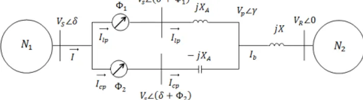
Fig 1 Tuned IPC in series with transmission line connecting two power systems
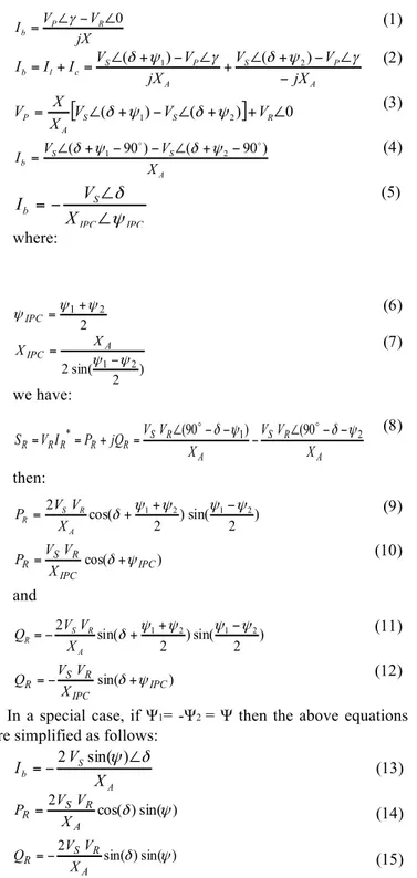
Fig 1 shows a tuned IPC in series with a transmission line connecting two power systems. Voltage and current equations modeling the behavior of the IPC are given as follows:
Application of Voltage Source Convertor in
Interphase Power Controller
M. A. Chitsazan, G. B. Gharehpetian, M. Arbabzadeh
) 1 ( jX V V
I P R
b 0 ∠ − ∠ = γ ) 2 ( A P S A P S c l b jX V V jX V V I I I − ∠ − + ∠ + ∠ − + ∠ = +
= (δ ψ1) γ (δ ψ2) γ
) 3 (
[
∠( + 1)− ∠( + 2)]
+ ∠0= S S R
A
P V V V
X X
V δ ψ δ ψ
) 4 ( A S S b X V V
I ( 1 90) ( 2 90) − + ∠ − − + ∠
= δ ψ δ ψ
(5) IPC IPC S b
X
V
I
ψ
δ
∠
∠
−
=
where: ) 6 ( 2 2 1 ψ ψ ψIPC = +) 7 ( ) 2 sin( 2 ψ1−ψ2
= A IPC X X we have: ) 8 ( A R S A R S R R R R R X V V X V V jQ P I V
S = *= + = ∠(90 −δ−ψ1)− ∠(90 −δ−ψ2)
then: ) 9 ( ) 2 sin( ) 2 cos(
2 δ ψ1+ψ2 ψ1−ψ2
+ = A R S R X V V P ) 10 ( ) cos( IPC IPC R S R X V V
P = δ+ψ
and ) 11 ( ) 2 sin( ) 2 sin(
2 δ+ψ1+ψ2 ψ1−ψ2
− = A R S R X V V Q ) 12 ( ) sin( IPC IPC R S R X V V
Q =− δ+ψ
In a special case, if Ψ1= -Ψ2 = Ψ then the above equations are simplified as follows:
) 3 1 ( A S b X V
I =−2 sin(
ψ
)∠δ
) 4 1 ( ) sin( ) cos( 2 ψ δ A R S R X V V P = ) 15 ( ) sin( ) sin( 2 ψ δ A R S R X V V Q =−
According to there equations for current, active and reactive transmitted power, they can be controlled by adjusting Ψ in PST. According to (14), the active power is related to cos (δ). It means that the output power is not influenced in a large scale by a change in δ. For example, by changing δ from -25 to 25, the minimum power in this range is only 9% less than the rated power. This is about 42% according to the fact that the reactive power is related to sin(δ). Changes in input power caused by voltage shifting can cause great changes in output power as above equations.
B. SSSC and IPFC
Series compensator based on VSC, i.e. static synchronous compensator (SSSC) injects the compensating voltage to the transmission line independent of the line current. Therefore, the equation between the power transmitted PR and δ becomes
a function of injected voltage and in a two-machine system it can be written as follows:
(16) ) 2 sin( ) sin( 2 δ δ X V V X V
PR= S + S Q
On the other hand, in Interline Power Flow Controller (IPFC), normally, series compensating capacitor is used for increasing the transmitted active power of a line and balancing load in a transmission system with parallel lines. However, regardless of their operations, series reactive compensators cannot control reactive power flow of the transmission lines and balance their loads properly especially when the ratio of the reactance to the resistance impedance (X/R) is low. Series reactive compensators decrease only the reactive part of the impedance therefore reduces X/R considerably and increase the flow reactive power and loss of the line. IPFC design, along with controllable series reactive compensator of each line cause the active power to flow in compensated lines directly. Thus, the active and reactive power flow becomes equal between lines. The active power flow reduces the pressure on overloaded lines, compensates voltage drop and reactive power demand as well as compensating dynamic disturbances more efficiently.
C. VSC-based IPC
As shown in Fig 2, in steady state condition, VSC-based IPC model is similar to IPC model, while in this model VSC creates phase shifting instead of PST. An active power source (synchronous diesel generator) is required due to voltage injection to the line current with different angles. Admittedly, it can be replaced by battery or the active power given the main source. This source provides the active power in steady state conditions in accordance to injected voltage and also variations in angle and magnitude of injected voltage in fault condition. IPC can omit the disturbances and reduce the active power variations. Thus, VSC-based IPC can do so and it can also inject active power to stabilize the output active power balance.
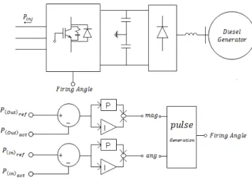
Fig 2 Circuit of VSC-based IPC
Fig 3 Switching control and control circuits
This equation shows that active power transmitted and its direction is independent of δ, which is the phase difference of two networks and has a small value. The cosines variation is
small from Λ
−25 to25Λ. So, controlling the active power and
its direction is done by phase variation in control voltage. It is driven from the equation that phase difference between two networks does not specify the active power direction, and also it has a little impact on the transmitted active power value.
As (16), the power transmission direction can be changed by the negative phase difference. According to vector addition law, if the angle of injected voltage is set between (-180+ δ,
δ), negative phase difference is generated and power in equation (17) will be positive and if this angle is set between (180+ δ, δ), positive phase difference is generated and the power in equation (17) will be negative. While the sign of the phase difference is independent of the magnitude of the injected voltage due to vector addition law, its magnitude is dependent to it. Therefore, the angle of injected voltage is appropriate for controlling the transmitted power and input power. The modulation (the magnitude of the injected voltage) is also used for controlling the injected power.
VSC structure, synchronous diesel generator, switching control and control circuits are shown in Fig 3. In VSC-based IPC the input active power and its direction is controlled by phase control. On the other hand, in case of phase or input source voltage variations and the active power alternation, the phase injected alternation can preserve the direction of the transmitted power (even if the input source is lagging to the network) and also reduce the input power variation by changing the phase of the injected voltage. The output active control is done by the magnitude of the injected voltage. Therefore, controlling these two parameters can control the injected voltage, and so injected and transmitted power. For IGBTs fire pulse production, the magnitude and the angle of the reference sinusoidal wave is produced by proper phase shifting for three phases with modulation and angle, and is compared to sawtooth pulse, which oscillates with switching frequency. Thus fire pulses are produced.
As shown in Fig 3, the required active power is stored in the capacitor by diesel generator, and power transmission is done via capacitor. Therefore, time delay of power transmission, which is produced when diesel generator is connected to the network, is eliminated. On the other hand, fuel consumed and its control are not significant. One of the other disadvantages of IPC is the usage of a discrete structure for producing a specified phase shifting, so as a specified phase shifting requires a specified circuit design and a new structure is used when the circuit condition changes and a new phase shifting is required. The strategy of phase shifting in VSC-based IPC eliminates this drawback so voltage injection -with proper magnitude and angle- can produce the line voltage with desired magnitude and angle. The vector addition of the line and injected voltages results in Vk. Due to vector addition law, if the modulation index is a small value; the phase variations have little impact on the magnitude of the resulted voltage that is then approximately equal to the input voltage.
III. SIMULATION
The advantage of using VSC-based IPC is that it can compensate the active power considerably via the injected voltage alternations as well as having IPC characteristics.
TABLEI
PARAMETER VALUES OF THE SYSTEM
Sender Source Voltage 20∠15KV
Network voltage 20∠0KV
Frequency 50 Hz Inductor L=31.8mH Capacitor C=318.2 µF Switching frequency F=2050 Hz
The suggested model is carried out in PSCAD environment. The system parameter values are shown in Table I. First the simulation results of uncontrolled VSC-based IPC and then the suggested VSC-based IPC are presented. Injected voltage to the line by VSC is constant in Uncontrolled VSC-based IPC like ordinary IPC. Thus it is expected that uncontrolled VSC-based IPC can eliminate the active power variations due to δ
alternations like IPC.
The variation values and their duration in input source parameters are shown in Table II. The purpose of these alternations is power flow variations in different conditions and analyzing the VSC-based IPC in operation in these situations.
(17) )
2 sin( ) 2 cos(
2
ψ
2ψ
2δ
++ −=
A R S R
It should be noted that these alternations are created by outside controlling of input source parameters.
TABLEII
THE VARIATION VALUES AND THEIR DURATION IN SIMULATION
0.3-0.45 sec 0.7-0.85 sec 1.05-1.2 sec Voltage
Variations 1 kV -3 kV
±3 kV Sinusoidal Phase
Variations 3 deg -8 deg
±3 deg Sinusoidal
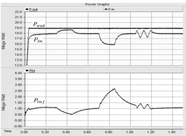
Fig 4 and Fig 5 show simulation results in case of power alternation in uncontrolled VSC-based IPC. As shown, POUT is the given active power to the network. PIN is the input active power and PINJ is the injected active power by VSC. Simulation is done in 3 times for δ and voltage.
Fig 4 shows simulation results of the power variations due to voltage alternations. As mentioned above, because of maintaining the intrinsic structure of IPC and injecting constant voltage, which decreases considerably the input voltage alternations in one of VSC-IPC branches, the active power variations are limited. Fig 4 illustrates active power variations due to voltage alternations.
Fig 4 Power flow variations due to voltage alternation in uncontrolled VSC-based IPC
According to (17), the magnitude of the transmitted power is directly dependent to the voltage variations and only a little portion of power variations due to voltage alternation reduction can be compensated by voltage injection. Therefore, as shown in Fig4 the main part of the input active power variation exists in the output active power. Simulation results of the variations in the active power due to δ alternations are shown in Fig 5. According to (13), the active power is almost independent of δ alternations. However, in these situations, the output active power still has oscillations while a noticeable portion of the input active power variations is omitted. As derived from Fig 4 and Fig 5, uncontrolled VSC-based IPC, which has a function similar to IPC, cannot control and stable the active power properly nevertheless its unique features.
This disability is more vital when the power variations are due to voltage alternation.
Fig 5 Power flow variations due to δalternation in uncontrolled VSC-based IPC
On the other hand, it can cause more problems if the VSC-based IPC is used for connecting the wind power plant due to great oscillations and disturbances of these power plants. Thus, the need for the active power control to give the desired and proper active power to the network is necessary.
Fig 6 Active power flow variations due to input voltage alternation in VSC-based IPC
Therefore, VSC-based IPC not only maintains the unique IPC features, but can also compensate the input active power variations properly with injecting the defined active power. Fig 6 and Fig 7 show the simulation results of suggested VSC-based IPC in case of the input active power variations.
Fig 7 Active power flow variations due to δalternation in VSC-based IPC TABLEIII
INPUT SOURCE PARAMETERS VALUE ALTERNATION AND THEIR DURATION IN
SIMULATION
0.3-0.45 sec 0.7-0.85 sec 1.05-1.2 sec Voltage
Variations 1 kV -3 kV
±3 kV Sinusoidal Input Power
Variation (Uncontrolle d VSC-IPC)
9.6% 27.4% 13.3% Uncontrolled
VSC-IPC 4.5% 13.6% ±8.5% Input Power
Variation (controlled VSC-IPC)
5.3% 18.3% ±7.9% Controlled
VSC-IPC 1.05% 1.84% ±1.31% TABLEIV
INPUT SOURCE PARAMETERS VALUE ALTERNATION AND THEIR DURATION IN
SIMULATION
0.3-0.45 sec 0.7-0.85 sec 1.05-1.2 sec Phase
Variations 3 deg -8 deg
±3 deg Sinusoidal Input Power
Variation (Uncontrolle d VSC-IPC)
6.38% 12.8% ±4.2% Uncontrolled
VSC-IPC 3.1% 4.3% ±1.77% Input Power
Variation (controlled VSC-IPC)
4.44% 11.67% ±3.35% Controlled
VSC-IPC 0.05% 0.31% ±0.12%
In Fig 7 the active power variations due to δ alternation is shown. It is driven that injecting the active power by VSC, can
control active power with appropriate quality as well as picking up many advantages of IPC for eliminating the active power variations due to δ alternations. Injecting voltage with proper phase difference while the power is changing due to δ
alternations can reduce the input active power variations. This will improve system dynamism, increase active power stability and supply the output active power properly.
TABLE III and TABLE IV represent the variations of the active power while the voltage or δ change in the defined pattern.
IV. CONCLUSION
In this paper, a new topology of IPC called VSC-based IPC is presented. This structure creates phase difference in line voltage by injecting proper voltage. VSC-based IPC has the majority of IPC characteristics, such as short circuit limiting, resonance creating at short circuit situation, no output power variations due to δ alternations and eliminating disturbances. Furthermore, this system can neutralize thoroughly active power oscillation due to voltage variations and stabilize output active power effectively in different conditions. VSC-based IPC can also provide a large range of injecting active power and producing desired angle and magnitude for voltage injection. In addition, it does not require a different structure for phase shifting as IPC. As a result, VSC-based IPC is a more powerful device for controlling the active power when the active power oscillation and disturbance happen a lot.
REFERENCES
[1] J. Brochu, P. Pelletier, F. Beauregard, G. Morin, "The interphase power controller, a new concept for managing power flow within AC networks", PWRD IEEE Trans., vol. 9, No. 2, Apr. 1994, pp. 833-841 [2] J. Brochu, F. Beauregard, G. Morin, J. Lamay, P. Pelletier, S. Kheir,
“Simulator Demonstration Of The Interphase Power Controller Technology”, IEEE Transaction on, Vol 11, No 4, October 1996, pp 1985-1992.
[3] P. Pelletier, J. Lamay, J. Brochu, F. Beauregard, G. Morin, “The Interphase Power Controller – A Robust Solution For Synchronous Interconnections And Management Of Flows”,AC and DC Power Transmissim , 29 April -3 may 1996, pp 291-296.
[4] J. Brochu, F. Beauregard, G. Morin, J. Lamay, P. Pelletier, S. Kheir, “The IPC Technology – A New Approach for Substation Uprating with Passive Short-Circuit Limitation”, Power Delivery, IEEE Power Delivery, vol. 13, 1998, pp. 233–240.
[5] F. Beauregard, J. Brochu, G. Morin, P. Pelletier, “Interphase Power Controller with Voltage Injection”, Power Delivery, vol. 9, Oct 1994, pp 1956-1962.
[6] J.Brochu, “Interphase Power Controllers”, Book, Polytechnics International Press, 1999.
[7] M.Mohamadi, G.B.Gharepetian "Study Of Power System Stability Using Thyristor Controlled -Interphase Power Controller”, ACMOS'05 Proceedings of the 7th WSEAS international conference on Automatic control, modeling and simulation, 2005, pp 208-214
[8] J. Brochu, F. Beauregard, J. Lamay, G. Morin, P. Pelletier, R.S.Thallam, “Application Of The Interphase Power Technology For Transmission Line Power Flow Control”,IEEE Transaction on, Vol 12, No 2, April 1997, pp 888- 894.
[10] J. Brochu, F. Beauregard, G. Morin, J. Lamay, P. Pelletier, S. Kheir, “Interphase Power Controller Adapted To The Operating Conditions Of Networks”,IEEE Transaction on, Vol 10, No 2, April 1995, pp 961-969. [11] E. Wirth, A. Kara, "IPCs With Conventional Or Electronically Switched
Phase- Shifting Devices-New Power System Components", Power Engineering Journal, vol. 14, No. 2, pp. 77 -80, Apr. 2000
[12] G.B.Gharepetian, H.Rastegar, M.Mohamadi, "Power System Stability Improvement Using Thyristor Controlled Interphase Power Controller" 36-th Universities Power Engineering Conference, UPEC 2001, Paper No.439, Swansea, Uk. , Sep. 2001.
[13] K.Habashi, J.J.Lombard, S.Mourad, P. Pelletier, G.Morin, F. Beauregard J. Brochu, J. Lamay “Steady-State Analysis of Power Flow Controllersusing the Power Controller Plane”, IEEE Transactions on Power Delivery, Vol. 14, No. 3, July 1999.
[14] J. Lemay, P. Berube, M.M. Brault, M.Gvozdanovic, M.I. Henderson, M.R.Graham, G.E.Smith, R.F. Hinners, L.R.Kirby, F. Beauregard, J. Brochu, "The Plattsburgh Interphase Power Controller", IEEE Transmission and Distribution Conference, vol. 2, pp 648-653, 1999.
1) Date of modification: 10/16/2012 2) Description of changes:
a. “Convertor” instead of “Convector” in the title
b. “Ψ1= -Ψ2 = Ψ” instead of “Ψ1=Ψ2 = Ψ” in the first line after Equation 12 (page 2). c. “(14)” instead of “(6)” in the third line after equation 15 (page 2).
d. Line 6 after Fig. 3 is written as: It is driven from the equation that phase difference between two networks does not specify the active power direction, and also it has a little impact on the transmitted active power value. (Page 3)