Improvement of Voltage Quality in Isolated Power Systems by
Using Series Compensation
K. Rajashekar Chowdary
1, V.L.Sumanthi
2, S.Hari
3, P.Ratnakumar
4, D.Ashoka
51
(Asst. professor Department of Electrical and Electronics Engineering, Lendl Institute of Engineering and Technology, Jonnada, Vizianagaram-535005)
2
(U.G Student Department of Electrical and Electronics Engineering, Lendl Institute of Engineering and Technology, Jonnada, Vizianagaram-535005)
3
(U.G Student Department of Electrical and Electronics Engineering, Lendl Institute of Engineering and Technology, Jonnada, Vizianagaram-535005)
4
(U.G Student Department of Electrical and Electronics Engineering, Lendl Institute of Engineering and Technology, Jonnada, Vizianagaram-535005)
5
(U.G Student Department of Electrical and Electronics Engineering, Lendl Institute of Engineering and Technology, Jonnada, Vizianagaram-535005)
ABSTRACT
The main objective of this proposal project is use of series compensator in improving voltage quality in isolated power system. It is observed that power system contains fluctuating non-linear load and high levels of harmonic distortions. The s.c is designed to maintain the fundamental frequency component of terminal voltage of protective load. In this process the power exchange exists between the s.c and external network. Based on this a new sc control strategy is proposed to adjust fundamental frequency component of load terminal voltage. The loads are also sensitive to short duration disturbance in the form of voltage sag/swells. Validity of the proposed technique is illustrated through mat lab simulation. As it is applied on the sc to achieve improved quality of supply in the power system.
Index
terms
- Harmonic power flow, isolated power system, phase shift, series compensation, voltagerestoration
I.
INTRODUCTION
Isolated power systems are commonly founded in rural and remote area of the world. These systems represent the alternative to grid connection, where interconnection to a large grid is not viable due to high cost and/or geographical obstacles. Furthermore, power systems such as those onboard of ships, in oil exploration areas and remote mining districts are characterized by limited generating capacity, supplying loads which can consist of significant amount of motor drives and power converters. The power systems are often considered weak in that they possess relatively low short-circuit ratio, in comparison to a grid. Network voltage control becomes a challenging task as a result. The power-quality (PQ) problem is compounded as the drive-converter loads are likely to fluctuate in conjunction with the mining or exploration activities.
consequence would be distortions in the voltage/current waveforms in the supply system, the extents of which are likely to fluctuate as the load changes [1], [2].
In addition to the drive load, one can also expect the presence of lower power capacity-sensitive loads, such as computers or electronic controllers in the power system. The equipments needed to ensure the proper functioning of the exploration/mining activities. The sensitive loads would be connected in parallel with the nonlinear drive. Often such sensitive loads also contain input rectifiers that are capacitive in nature. The combined sensitive loads may be represented by the parallel Circuit shown in Fig. 1. While the total capacity of the sensitive loads could be much smaller than that of the main drives, the distorted supply voltage is harmful to the sensitive loads. Excessive voltage distortions could cause the sensitive loads to maloperate. The loads are also sensitive to short-duration disturbances, in the form of voltage sags or swells. The disturbances can be due to faults or most likely, the fluctuating load cycles of the main drives. In the latter case, voltage flickers can occur and they can be of major concern. Thus one important consideration in the design and operation of the power system would be to ensure that the quality of supply to the sensitive loads comply with that prescribed under industry standards, such as the ITI curve
[3].A traditional method to achieve improved PQ is to use passive filters connected at the sensitive load terminals [4]. However, this practice has some shortcomings: the effectiveness of the scheme could deteriorate as the source impedance or load condition changes; it can lead to resonance between the filter and the source impedance. For these reasons, active filters such as that described in [5] may be used. Essentially an active filter, connected at the sensitive load terminal, injects harmonic currents of the same magnitude but of opposite polarity to cancel the harmonics present there. However, as noted earlier, harmonic distortions are only part of the problem faced in such a network: the variations in the drive load would result in voltage sag/swell or flickers appearing in the upstream voltage VS. Thus, the challenge is to regulate the sensitive load terminal voltage VL so that its magnitude remains constant and any harmonic distortion is reduced to an acceptable level. In a recent study, [6] proposes a series compensation method to mitigate the harmonics problem for the
compensation for voltage sag/swell or flicker has not been considered. Series voltage compensation methods have been discussed in [7], [8]for the mitigation of short-duration voltages/swells but the presence of harmonic voltages/current in the networks has been ignored This paper intends to fill this gap. Specifically, the investigation is to develop a method to control the fundamental component of VL . The control is achieved by regulating power flow via phase angle adjustment. Unlike the previous methods of [6]–[8], the investigation also shows that the voltage-sag ride through capability of the sensitive load can be improved through importing harmonic power from the external system into the SC.
II.
HARMONIC MITIGATON AND
POWER FLOW
With regard to the problem in hand, it is assumed that the nonlinear converter and the sensitive loads are balanced. In what follows, symbols with the subscript ―S‖ denote quantities which are associated with the upstream source, ―L‖ for those associated with the sensitive load, ―D‖ with the downstream main converter drive and ―C‖ with the series compensator. Subscript ―h‖denotes the harmonic component and ―1‖ that of the fundamental. Voltage and current phasors are denoted with a symbol―→‖ on the top of the respective quantities. Their magnitudes (rms) are shown as capital letters while their peak values are denoted ―^‖ on top. Vectors are denoted by bold
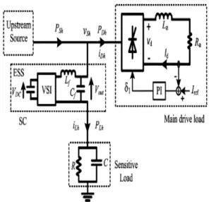
letters. As shown in Fig. 1, the central part of the SC is the voltage source inverter (VSI) and the energy storage system (ESS). As PWM switching scheme is often used in the VSI, harmonics are generated and filtering is required. Lf and Cf are the filter inductance and capacitance. While the detailed function of the SC under voltage sag/swell can be found in [7], [8], suffice to state that the VSI synthesizes the required voltage quantity V (out) which would be injected in series with. VLThe ESS would act as a buffer and provides the energy needed for load ride through during a voltage-sag. Conversely, during a voltage-swell, excess energy from the network would be stored in the ESS so that VL can be controlled.
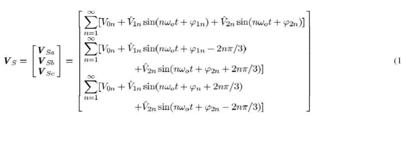
CONTROL OF HORMONIC DISTORTION Distorted phase voltage Vs on the upstream source-side of the sensitive load can be expressed as shown in (1) at the bottom of the page for phases a, b, and c where � is the fundamental frequency, n is the harmonic order; V0n is the zero phase sequence voltage component; V1n and� � are the peak and phase of the positive phase sequence voltage
component; V2n and � � are the peak and phase of the negative phase sequence voltage component. When expressed in this manner, Vs would be completely general and would include unbalances in the network.
Clearly, distorted voltage is undesirable at the sensitive load terminals.
Fig. 2. Equivalent circuits of the sensitive load-SC branch Fig.3.Sensitive load-sc branch. (a) For (a) fundamental component and (b) hth harmonic Equivalent circuit describing harmonic Component compensation (b) phasor diagram for the Hth harmonic
The fundamental components of the voltages contained in (1) are
Where, Vsh contains all the harmonic components in (1). The proposed voltage injection method shown in [6] is to inject voltage components in series with VS and the desirable injected voltages
would contain all the harmonic components in (1). Hence, from (1) and (2), the injected voltage from the
SC would be
Thus far, one has only considered the condition that Vs contains harmonic distortions. However, a voltage sag/swell may appear in Vs and hence, Vs1 could differ from specified desirable value. Assume the desirable load side fundamental voltage components are
Ideally, the injected voltage from the SC would then have to be
Extracting the fundamental component Vout of and denoting it by the phasor V1, one obtains
In this way, the equivalent circuit describing the sensitive load branch can then be decomposed into the fundamental frequency component and harmonic component circuits, as shown in Fig. 2(a) and (b), respectively.
Under such an ideal compensation situation, there will be no harmonic component in the sensitive load current IL and thus, no harmonic energy exchange can exist between the SC and the external system. Energy exchange is only due to the fundamental frequency components of Vout andIL. In practice, however, the SC has a finite bandwidth. A phase lag inevitably exists between Vsh and IL the actual injected voltage from the SC. The lag results in voltage pulses appearing at the terminals of the sensitive load. As the RC sensitive load impedance decreases with frequency, the voltage Pulses will cause large harmonic current distortions to appear in a practical method to limit the THD in IL to a prespecified level has been proposed in [6]. It involves a new strategy to control Vout and the use
of a series filter. Essentially, is obtained from IL, through a lead-lag feedback scheme while the series filter reduces high-frequency harmonics in. Hence, there will be harmonic current ILh in the circuit, as shown in Fig. 3(a). As Vsh contains harmonic components, harmonic power flow can exist between the SC and the external system.
Power Flow Control through SC
Having described the harmonic mitigation principle and noting that harmonic power flow would exist in the SC circuit, detailed analysis will be carried out next. For the convenience of Analysis and assuming Negligible in the network, a single-phase equivalent system (phase ―a‖) is used to describe the three-phase system shown in Fig. 1.
Let the frequency component of the sensitive load current, , IL1betaken as the reference phasor.
Suppose the upstream load change has resulted in momentary sags/swells inVS1. The aim of the compensation is to ensure the magnitude of VL1is maintained constant. If one were to introduce
phase-shift into ����� , one would obtain a new injection voltage from that described by (6), i.e.,
Where h is harmonic order, VS1and�� are the peak value and phase of the harmonic component of the actual injection voltages ILh and �ℎ are the peak value and phase shift Of the hth harmonic
component in IL The cycle-average value of PC (t) is seen to contain two terms: a contribution each from the Fundamental frequency component and the harmonics
Where PC1 corresponds to the power flow of the fundamental frequency component. It is controllable through the introduced phase shift ��o VL1in. Thus, Pc can be varied through Pc1 via adjustments in�.Pch Corresponds to the power flow of the harmonic components. In the process of varying Pc1, Pch is assumed constant over the time interval when is being adjusted. This is a reasonable assumption because the adjustments in� can be accomplished in a much shorter time, as the rate by which the electro-mechanical drive load and therefore the harmonic level can vary is slow in comparison. Also, as the only significant source of energy storage in the SC is the ESS, would indicate an export of power from the SC to the external system. It will cause a decrease in the voltage across the ESS. Conversely will begin to rise if the SC starts to import from the external system. Variations of will affect the compensation capability of the SC and excessive voltage rise will damage the ESS. Hence,
In Fig. 4, the main load is shown as a dc drive system. The dc motor, represented by the equivalent RL circuit, is assumed to be fed by a six-pulse controlled converter. The firing angle of the converter determines the average value (VD) of the output voltage. The converter output current can be controlled via a PI regulator which changes � 1In this way, the effect of a load change can be readily studied by altering the reference current Iref. Details of the control technique can be found in [9].The main converter load is the dominant harmonic source in the power system due to its much larger capacity, compared to the SC and sensitive load. The SC is assumed to be ―ideal‖ in that whatever harmonics generated by the VSI are effectively dealt with by its LC filter. The SC is a harmonic ―sink.‖ In this way, the harmonic power (PDh) produced by the nonlinear main drive load is dissipated in the upstream source impedance and is absorbed by the sensitive load. The harmonic power flow to the upstream source (PSh) and into the sensitive load (PLh) is as shown in Fig. 4
FIG: Harmonic power flow in the isolated system: hth harmonic component.
To assess the value of (PDh), the harmonic contents of VS (t) and Id (t) have to be known. In order to do so, the following Assumptions are made: the upstream source consists of balanced sinusoidal EMF of constant voltage with equal inductances; its phase ―a‖ terminal voltage is of the formVS1 (t) = Vm ����� and Id is assumed to be ripple free The firing angle� changes as load condition varies and in general� , and the overlap angle of the converter determine the exact waveform of VS (t) [10]. Harmonic components of VS (t) and Id (t) could be obtained through Fourier analysis and can be evaluated. Furthermore, once VS (t) has been determined, can also be determined as the source
harmonic power (PLh) is diverted to the SC branch. Part of this harmonic power will be absorbed by the sensitive load. Once, (PDh), (PSh) and (PLh) have been obtained, the harmonic power imported by the SC, Pch could be evaluated. Numerical examples will now be used to illustrate how the harmonic power flow in the network can be assessed.
III.
VOLTAGE RESTORATION
Having considered harmonic power flow in the isolated power system, voltage restoration will be examined next. As stated earlier, voltage control of the ESS is necessary to ensure the proper operation of the SC and to protect the device. Thus it is desirable to regulate the power transfer between the SC and the external system so that Vdc across the ESS of the SC can be maintained. Once this is achieved, the SC will be able to exercise network voltage control, in a manner described in [7] and [8]. The SC will assume this role of voltage control until such time when the excitation system of the upstream generator becomes effective in forcing the generator to share the voltage regulation duty. However, if the excitation system is a slow-acting electro mechanical type, the sensitive load would have to rely very much on the SC to achieve a VL constant. It is therefore necessary to examine the extent by which the SC can exercise such control. Furthermore, in terms of voltage quality, it is the fundamental component of VL which is of the greatest importance. Hence in what follows, the focus is on maintaining the magnitude of this Voltage component denoted VL1. The condition of zero power transfer between the SC and the
External system is examined first. From (11), this means that, that is Pch>0, when (24) As shown in Section II, it is concluded that the SC absorbs harmonic power from the external system, that is, . Thus, from (24), at zero power transfer, the SC should export power of the fundamental frequency component equal to an amount Pch in order to balance the imported harmonic power. Next, define an equivalent fundamental frequency component voltageof the SC injected voltage V (out) such that VP IL1=PCh
The last expression means that when the projection of the fundamental frequency component of V (out) (shown as VL1in Fig. 5) onto IL1 is VP, the condition for zero power transfer is reached. As shown in the previous Section, IL1and Pch are known quantities for a given power system operating condition.
VOLTAGE SWELL
where is shown as the reference phasor. Since VL1denotes the desired voltage magnitude at the sensitive load terminals, the aim is to maintain it constant through the action of the SC. Assume the sensitive load is of constant power factor at the fundamental frequency. Therefore from (11),, �=� +�that is, the phase angle between
IL1and�� is constant at .� �is the phase shift described in Section II. From (7), the SC injected voltage is
V1=VL1-VS1 PC1=Re{V1*IL1}
IV.
VOLTAGE SAG
The above analysis can be extended to deal with the event of voltage sag, that is, . Fig. 5(b) shows a general phasor diagram during voltage sag. By similar reasoning as shown for voltage swell, when
V.
ILLUSTRATIVE EXAMPLES
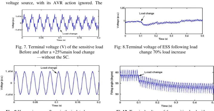
The example shown on Fig. 4 may now be used to verify the effectiveness of the SC in enhancing the voltage quality of the power system. The upstream generator is represented as a220-V voltage source, with its AVR action ignored. The
source impedance (ZS) is assumed to be 0.05 p.u. and .q=20 the main load converter is assumed to be a six-pulse controlled rectifier. The dc motor, as shown in Fig. 4, has Ra=2ohm and La=25mH. The rating of the dc load is 2 kW and it is also the base value chosen for the system. The current of the motor is controlled and load change is simulated by changing (Iref) the of the motor. The capacity of the sensitive load is assumed to be0.2 kVA (i.e.,) k=10 and its power factor at the fundamental frequency is 0.75 leading. The sensitive load level is assumed to be at full load in these examples. The SC was modeled as a PWM inverter and its detail model is given in [13]. A capacitor is used as the ESS. The simulations were accomplished using MATLAB. The voltage at the sensitive load terminals is as shown in Fig. 7 when a load change occurs but without the SC in service. Before the load change, the motor drive is at 0.5-p.u. loading and it can be shown that VL has a THD level of 30%.Fig. 8 shows the corresponding waveforms when the SC is in-service. With harmonics compensation by the SC, the sensitive load is protected against the harmonic distortion and the THD of the voltage has been significantly reduced to 3%.
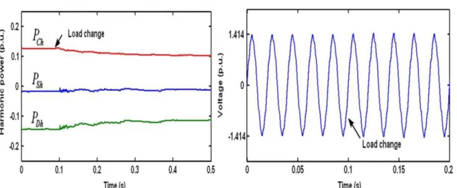
The harmonic power flow (expressed on the base of the sensitive load capacity of 0.2 kVA) in the isolated power system is shown in Fig. 9. Prior to a 25 % load change Pch, imported by the SC during compensation is about 0.13 p.u. Ona0.2-kVA base, IL1=1p.u. and from (25),VP=0.23 p.u. Thus, �=�. 13 p.u. According to (33), the sag ride
through limit
Fig. 7. Terminal voltage (V) of the sensitive load Fig: 8.Terminal voltage of ESS following load Before and after a +25%main load change change 70% load increase —without the SC.
Fig. 9 Harmonic power flows in the isolated power Fig12: Terminal voltage of the sensitive load with system prior to and after the 25% main load increase sc 40% load increase.
is about 0.62 p.u. The % load change has resulted in a70% voltage sag, as shown in Fig. 7, when the SC is not in service. The load change has caused to decrease to about 0.1p.u. This means that also decreases correspondingly. Is now about 0.65 p.u. but it is still less than the load power factor. Hence the SC can still assist the load in riding through the sag,
Fig. 13. Terminal voltage of ESS for a 40% load increase.
As shown in Fig. 8. Fig. 10 shows the ESS voltage during restoration: decreases marginally and is a restored in10 cycle or so in the face of the voltage sag. Fig. 9 shows that as the load changes, also varies because the firing angle is adjusted. This can be seen in Fig. 11.From the above results, the VA capacity of the SC has been evaluated using Fig. 5(b) and is estimated to be some 36% of the sensitive load rated capacity. The corresponding .Fig. 12 shows the waveform of during a 50% voltage sag when the dc motor load is increased by 40%. The sensitive load Fig. 10. Terminal voltage of ESS (V) following load change: 70% voltage sag. Fig. 11. Firing angle of rectifier during main load changes due to the 70%voltage sag. Fig. 12. Terminal voltage (V) of the sensitive load: with SC for a 40% load increase. Fig. 13. Terminal voltage of ESS for a 40% load increase. Is seen restored through the voltagesag.However, the load increase is so large that it has resulted in to be below the limit predicted by (33). Is sustained only through the continuous of from the ESS. Hence, the
voltage of the ESS cannot be maintained, as is shown in Fig. 13.
Similar studies have also been carried out under voltage swell conditions to confirm that the SC can indeed provide satisfactory ride through performance for the power system. A full prototype of the SC is under development, with the view to use it to validate the results of the analysis described earlier
VI.
CONCLUSION
REFERENCES
[1] I. Jonasson and L. Soder, ―Power quality on ships-a questionnaire evaluation Concerning island power system,‖ in Proc. IEEE Power Eng. Soc. Summer Meeting, Jul. 2001, vol. 15–19, pp. 216–221.
[2] J. J. Graham, C. L. Halsall, and I. S. McKay, ―Isolated power systems: Problems of waveform distortion due to thyristor converter loading,‖ in Proc. 4th Int. Conf. Power Electronics and Variable-Speed Drives, Jul. 1990, vol. 17–19, pp. 327–330.
[3] ITI (CBEMA) Curve Application Note, [Online]. Available: http://www.itic.org., Inf. Technol. Ind. Council (ITI).
[4] J. C. Das, ―Passive filter—Potentialities and limitations,‖ IEEE Trans. Ind. Appl., vol. 40, no. 1, pp. 232–241, Jan. 2004.
[5] H. Akagi, ―New trends in active filter for power conditioning,‖ IEEE Trans. Ind. Appl., vol. 32, no. 6, pp. 1312–1322, Nov.
1996.
[6] S. S. Choi, T. X.Wang, and E. K. Sng, ―Power quality enhancement in an isolated power system through series compensator,‖ presented at the 15th Power System Computation Conf., Liege, Belgium, Aug. 2005.
[7] N. H. Woodley, L. Morgan, and A. Sundaram, ―Experience with an inverter-based dynamic voltage restorer,‖ IEEE Trans. Power Del., vol. 14, no. 3, pp. 1181– 1186, Jul. 1999.
[8] S. S. Choi, B. H. Li, and D. M. Vilathgamuwa, ―Dynamic voltage Restoration with minimum energy injection,‖ IEEE Trans. Power Syst., vol. 15, no. 1, pp. 51–57, Feb. 2000.
[9] P. C. Sen., Principles of Electric Machines and Power Electronics, 2nd ed. New York: Wiley, 1997.
[10] E. W. Kim bark, Direct Current Transmission. New York: Wiley, 1971. [11] J. P. Tamby and V. I. John, ―Q’HARM-a
harmonic power-flow program For small power systems,‖ IEEE Trans. Power Syst., vol. 3, no. 3, pp. 949–955, Aug. 1988. [12] G. J. Wakileh, Power System Harmonics:
Fundamental, Analysis and Filter Design. New York: Springer, 2001.