Abstract— This article presents a different topology for the magnetic circuit of permanent-magnet motors, using the concept of Axial Flux Concentration. By means of longitudinal extension of the rotor length beyond the stator core, a substantial increase in the flux per pole is enabled, improving the general performance of the machine. Even in low cost motors with ferrite magnets, this improvement is easily achieved utilizing the proposed scheme. With rare-earth magnets this technique permits a higher torque density, contributing to the compactness of the machine. This configuration is suitable for several magnetic topologies, but particularly for small diameter and low pole number permanent-magnet motors of the embedded-magnet type.
The proposed topology is briefly described and the theoretical aspects presented. It is shown that, from the stator point of view, this scheme behaves like a conventional motor with fictitious equivalent magnets with augmented remanent flux density and recoil permeability. A 3D finite element modeling is performed to validate the theoretical analysis permitting some additional conclusions concerning magnetic saturation. The methodology is applied to a prototype DC brushless motor constructed for research purposes, composed of a stator and two rotors of different lengths, both with embedded NdFeB magnets. Various characteristics are compared, concerning flux per pole, torque, power density and efficiency. The improvement in the performance of the axial flux concentration rotor is confirmed by experimental results, in accordance with the theoretical previsions.
Index Terms— DC Brushless rotating machines, Magnetic circuits, Permanent-magnets, Flux concentration, Synchronous motors.
I. INTRODUCTION
Permanent-magnet (PM) machines have been increasingly utilized in the last years, both in
fractional and integral horsepower drives. In domestic appliances and on-board automotive systems,
among others, brushless motors are progressively substituting those with conventional technology.
More recently, brushless PM motors have been systematically proposed for electric and hybrid
vehicle propulsion. In low power applications, they are usually excited by Ferrite PMs, mainly due to
their low cost and prompt availability [1]-[2]. In motors with improved performance or in applications
where low weight and high power densities are required, as in vehicle propulsion systems [3],
Magnetic topology with axial flux
concentration: a technique to improve
permanent-magnet motor performance
Raul D. Paiva Jr., Viviane Cristine Silva, Silvio Ikuyo Nabeta, Ivan E. Chabu
Department of Electrical Energy and Automation Engineering, Polytechnic School, University of São Paulo, São Paulo, Brazil ( email: [email protected], [email protected], [email protected],
stronger rare-earth magnets are preferred, despite their high cost and manipulation difficulties inherent
to their use [4].
Regardless of the magnet material, various topologies [5] are possible for the magnetic circuit of
brushless machines. Surface-mounted and interior PM motors present in general similar performances
[6]-[7], the choice between them being a matter of design optimization depending on the particular
application [8]. Rotors with surface-mounted magnets have simpler construction, but present severe
limitations in high speed machines or in drives installed in harsh environment [9]. Buried magnets are
a common practice in rotor design, generally resulting in a more rugged construction. At the same
time, these embedded-type configurations permit some degree of magnet flux accumulation, mainly in
high-pole-number motors [10]. In such cases, radial magnets with great depth compared to rotor
diameter, or large h/D ratio (see Table II), as well as arrangements with inclined magnet pieces, permit individual magnet fluxes to add and increase the airgap flux density level [11]-[13]. In small
diameter rotors with low-pole-number, this accumulation effect is practically nonexistent.
A different scheme for magnet flux concentration, called Axial Flux Concentration (AFC), was
firstly proposed in a previous work [14], in order to achieve an appreciable increase in the airgap flux
density, even with low pole number and small diameter rotors. By that means, an overall
improvement in the machine performance becomes possible, even with the utilization of Ferrite
magnets. In motors with rare earth magnets, this technique leads to an increased torque density,
contributing to machine compactness and low weight, needed in some critical applications.
The AFC technique, briefly revised in section III, allows the magnetic circuit of the machine to
operate with an increased airgap flux, which would be the same as that provided by fictitious
equivalent magnets with higher remanent flux density and higher recoil permeability. This concept is
particularly suited for machines with embedded magnet rotors, and the required additional magnet
area can be easily accommodated even in small diameter rotors. This topology is suitable for PM
synchronous motors and generators, as well as brushless DC motors.
This paper presents an extension of [14] with more discussions and numerical simulations, as well
as enhanced experimental results. Moreover, a prototype was constructed in order to validate the
proposed topology.
II. MAGNETICCIRCUITTOPOLOGY
Motors with magnets embedded in the rotor are the prime choice for high speed applications, as
well as for drives subjected to high temperatures or submitted to intense vibration or shocks [15]. This
topology is also well suited for field weakening motors, due to minor risk of PM demagnetization
[16]. In addition, this configuration is in general preferred when utilized in sensorless control due to
more precise rotor position detection [17] - [18]. Unfortunately, machines with this configuration
g o p
p
B B
(1)
where p is the number of pole pairs and Bop is the flux density in the magnets at the operation point of the magnetic circuit1 . Since Bop is slightly lower than the remanence of the magnet Br , the airgap flux density approaches this value only in motors with more than 6 poles. In typical 4- or 6-pole
motors with conventional embedded Ferrite magnets, whose Br is about 0.4 T, the resulting Bg usually ranges from 0.25 to 0.40 T. These are very low values if a reasonable performance is required.
A conventional embedded magnet motor is described in [14]. The flux per pole in that rotor
configuration is given by:
2
p g f
D L B k p
(2)
where D is the rotor diameter, L is the core length and kf is the form factor of the spatial distribution of flux density in the airgap.
The operating point of the magnetic circuit [19] is obtained combining the demagnetization
characteristic of the magnet (where μrec is its recoil permeability) with the magnetic circuit load curve. In reference [14] a direct relationship between the peak value of magnetic flux density in the airgap,
Bg, and Br is obtained, as follows:
4
1
g r
f d
p h A
B B
D k k A
(3)
The constant A is given by:
8
f d
r e c g s
D b k k A
p h l k
(4)
where kd is the fringing and leakage flux factor, h is the height of the magnet pieces, lg is the airgap length including Carter's coefficient, b is the magnet thickness and ks the saturation factor of the whole magnetic circuit.
The operating flux density of the magnet, Bop, is calculated by:
1
o p r
A
B B
A
(5)
The airgap flux density, Bg, is the most relevant parameter to evaluate motor characteristic, as well as an important design constraint [9]. With the aid of (3) and (4) one can easily estimate Bg from Br , since those equations are dependent only upon dimensional parameters and on design factors.
Therefore, in motors with few number of poles, the parameter A given by (4) is far larger than unity. Considering that in small rotors the height of the magnets is in general appreciably smaller than
rotor diameter, (3) becomes approximately equal to (1). As already stated, this means that the
conventional embedded magnet motor presents modest characteristics when a poor magnet material is
utilized, such as Ferrite.
1
Eq.1 applies only for small number of poles, e.g. 2 to 8. When p becomes too large (p→ ∞), the small space available in
III. THEAXIALFLUXCONCENTRATIONCONCEPT
With the purpose of increasing the airgap flux density, a modified topology of the embedded
magnet rotor is proposed. The first idea was based in the Halbach magnet array, where additional
suitably-positioned magnet pieces may “guide” the flux through the magnet itself, thereby increasing
its value [20]-[21]. Here, additional magnets are also utilized, but the flux takes an axial path by using
an appropriate magnetic circuit configuration.
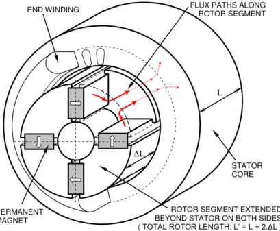
The proposed AFC topology, illustrated in Fig. 1, has the same cross-section as the conventional
embedded magnet rotor. The main difference is that the rotor, including the magnets, is extended
axially to a length L’, larger than the stator length, L. In this new configuration, there is an additional amount of flux produced by the portion of the magnet that exceeds the stator length, in both sides of
the rotor. This extra flux enters circumferentially in the rotor segment extensions, and flows axially
through the ferromagnetic material, towards the center of the rotor. Except for a small amount of
fringing flux, most of this additional flux takes the axial direction due to a lower magnetic reluctance
in the center of the rotor, placed inside the stator bore. Once this flux reaches the center of the rotor it
is added to the flux created by the magnets located in there. Then, the total flux turns up and leaves
the rotor in the radial direction, towards the stator. Hence, the total flux that crosses the airgap is
increased when compared with the conventional rotor (with same length as the stator). The arrows in
Fig. 1 indicate schematically the axial flux paths, which will be shown again ahead, in section V, with
the aid of a 3D Finite Element Analysis (FEA).
Fig. 1. Schematic drawing of the magnetic topology for the embedded magnet rotor with the proposed AFC concept.
It can be noticed in Fig. 1 that the additional length of rotor stays beneath the stator end windings,
which is a partially empty space in electrical motors. In practical machines this space may be
occupied by bearings and occasionally by rotor position sensors. Less common in PM motors, it may
STATOR CORE
L
ΔL END WINDING
PERMANENT MAGNET
FLUX PATHS ALONG ROTOR SEGMENT
be necessary to accommodate yet some kind of ventilating blades in this region. However, in low pole
number motors the stator end windings are relatively large, even with fractional pitch coils. Moreover,
even in optimized designs there usually remains sufficient space for a certain amount of rotor
extension, keeping the overall length of the motor unchanged.
The mechanical supporting of rotor segments may be accomplished through many ways. The use of
non-magnetic retaining rings, in the portions of the rotor protruding out of stator core, is an efficient
solution for solid ferromagnetic segments made of mild steel or soft magnetic composites [14].
Punched rotor segments with ferromagnetic steel bars inserted in appropriate holes is also a usual
construction [22]. The steel bars are used for mechanical retaining of the whole rotor and serve at the
same time, in this AFC scheme, as axial flux conducting paths.
In the proposed topology, by neglecting in a first moment the extra saturation of the rotor segments
or other flux paths, the equations utilized to obtain the flux per pole or flux in the magnets hold,
provided that appropriate lengths are considered, as shown in [14]. Performing the same development
as in section II, the relationship between the peak value of magnetic flux density in the airgap, Bg, and
Br is now given by:
4 '
'
g r
f d
p h A L
B B
L L
D k k A L (6)
Comparing equations (6), (3) and (5) one can establish an equivalent operating condition for the
magnetic circuit:
' '
'
o p r
A B B L A L (7)
where B’op is the flux density in the equivalent permanent-magnet at the operation point of magnetic
circuit and B’r is the equivalent permanent-magnet remanent flux density.
This is the flux density associated with an equivalent PM exhibiting the following equivalent
remanence:
' 'r L rB B
L
(8)
Considering appropriately B’r and B’op , the following equivalent recoil permeability, μ’rec , for the
magnet can be written:
' '
r e c L L r e c
(9)
The meaning of such equivalence resembles a conventional embedded magnet rotor, with the
original rotor length, excited by a hypothetic magnet material with an increased Br and a higher μrec, when seen by the stator. Fig. 2 illustrates this equivalence, where the dashed line stands for the curve
of the actual PM, whereas the solid line represents the fictitious magnet characteristic.
At this point a question may arise concerning the appropriate choice of the new length L’, namely
how long it could be. It can be noticed from (6) to (8) that the longer the rotor, the higher the flux
might offset the expected effect of increasing Bg.
Fig. 2. Characteristic curve for the equivalent PM in the magnetic circuit with AFC [14].
IV. THEPROTOTYPEMOTOR
Aiming to quantify the effects of the proposed AFC technique, a three-phase PM brushless DC
motor was developed for research purposes. The prototype was constructed with one stator and two
rotors: the first one, ROTOR 1, with the same axial length of the stator, L, and the second one,
ROTOR 2, with an increased rotor length, L’, where the AFC concept has been applied. The rated data of the motor with ROTOR 1 are summarized in Table I.
TABLE I. RATED DATA OF THE MOTOR1
Mechanical power 1.12 kW
Speed 2100 RPM
Torque 5.1 N.m
Fundamental frequency 70 Hz
Line voltage 300 V
Current 4.2 A
Number of poles 4
Number of phases 3
Cooling method TENV2
1Normal rotor, without AFC 2Totally Enclosed Non Ventilated
The prototype was manufactured with a conventional stator core, made of silicon-steel laminations,
as well as a standard three-phase star-connected winding [23]. The slots are skewed aiming to reduce
the pulsation in the airgap flux density distribution. The rotors were made of carbon steel laminations,
retained by a ferromagnetic steel bar, which has the additional function of providing an axial flux path
in the longer rotor. The two rotors have exactly the same cross section, the only difference being the
axial length of the core, as well as the length of the magnets. As standardized magnet pieces are
utilized, the increased rotor length is determined by the width of four magnet pieces utilized in each
pole, instead of three for the normal length rotor. The shaft was made of non-magnetic stainless steel
and the PMs are of rare-earth NdFeB type, which were radially retained in the rotor slots by means of
HcH’op
MAGNETIC FIELD
μ
recHop
MAGNETIC FLUX DENSITY
EQUIVALENT PERMANENT MAGNET CURVE
ACTUAL PERMANENT MAGNET CURVE
MAGNETIC CIRCUIT CHARACTERISTIC
μ
’
rec B’opBop
Br
brass wedges. Fig. 3 depicts the prototype structure.
Fig. 3. Drawing of the manufactured brushless motor prototype. (A) Motor with normal or original rotor. (B) Motor with longer rotor where AFC occurs. (C) Cross-section view.
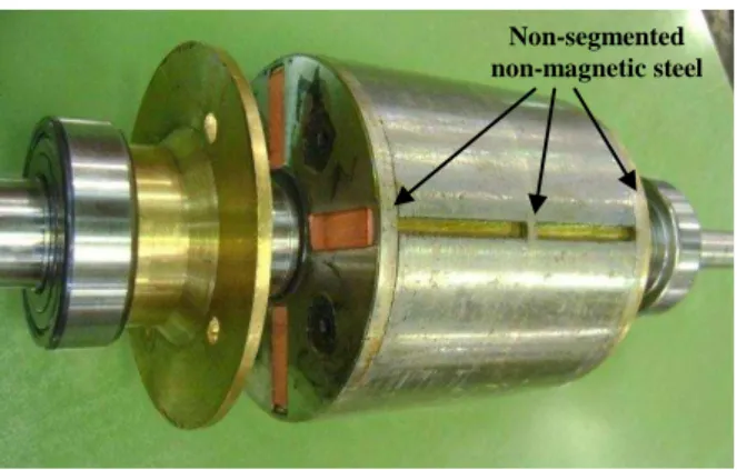
In both sides of the rotor and in its middle position there are non-magnetic, non-segmented steel
plates, which are used for sustaining the magnetic steel bars and the rotor segments as well. This set is
press fitted against the shaft. The entire rotor is a very rugged structure, suited for operating at high
speeds and in harsh environments subjected to shock and intense vibration.
Fig. 4 shows a picture of both prototype rotors. Details of the rotor construction are shown in Fig. 5.
The PMs are standardized components made from rare-earth NdFeB in the form of prismatic pieces,
inserted along the four rotor slots. Limiting operational temperature of the magnets is 150°C.
The main dimensions and parameters of the prototype are listed in Table II. The form factor is
obtained from the flux plot in the airgap, considering a smooth surface stator. The leakage factor is
evaluated by computing the permeance paths of the leakage flux in the rotor. The saturation factor is
evaluated by computing the magneto motive force required by the ferromagnetic parts of the magnetic
Fig. 4. Rotors of the prototype. Upper rotor is the conventional - ROTOR 1, with the same length of the stator. The lower rotor - ROTOR 2, is that where the AFC occurs, due to its extended length.
Fig. 5. Details of the rotor construction. Radial slots are for PM assembly. Lateral plates are for rotor mechanical supporting.
TABLE II. MOTOR DIMENSIONS AND PARAMETERS
Parameter Value
Stator outer diameter 182 mm
Stator length –L 78 mm
Number of stator slots 24
Rotor diameter –D 94 mm
Original rotor length –L–ROTOR 1 78 mm
Extended rotor length –L’–ROTOR 2 104 mm
Airgap –lg–Carter’s factor included 1.057 mm
Magnet height –h 25.4 mm
Magnet thickness –b 8 mm
Number of magnets - ROTOR 1 3 pieces per slot
Number of magnets - ROTOR 2 4 pieces per slot
Form factor –kf 0.938
Saturation factor –ks 1.071
Leakage factor –kd 1.228
Salience ratio –Xd / Xq 0.479
Magnet remanence –Br 1.18 T
Recoil permeability –μrec 1.06
Stator phase turns –Nph 152 turns/phase
Conductor / Slot fill factor # 16 AWG / 57 %
Phase resistance @ 20°C 1.02 Ω/ph
Winding factor –Kw 0.909
1 / 0.9662
Skew factor –Ksk 0.9171 / 0.9872
1
Rectangular flux density distribution 2 Fundamental component of flux density distribution Non-segmented
Using values of Table II in (4) and (3), the following parameters and flux densities results for
ROTOR 1: A = 5.58, Bg = 0.598 T. However, with ROTOR 2, by applying (6), one gets Bg = 0.758 T, which represents an increase of 26.8%.
From the stator point of view, this is equivalent to use a conventional rotor, with the same stator
length, excited by fictitious equivalent magnets with B’r = 1.57 T, as computed by (8), and 33%
higher recoil permeability, μ’rec. These modified values can be used in a 2D Finite Element (FE) modeling of the AFC motor, as an alternative to the high computational cost and effort of a 3D FEA.
This appreciable increase in Bg, while keeping the original stator winding and current, affects the capability of the motor in the same rate, namely 26.8% in both torque and power, at the same speed.
The overall dimensions of the motor remained the same, as shown in Fig. 3.
The weight of the stator active part, including magnetic core and winding is 14.1 kg. The weight of
ROTOR 1 active part, including core and PMs, is 4.9 kg, and for ROTOR 2 it is 6.6 kg. The weight of structural parts, such as frame, end shields, shaft and bearings, totalize 8.4 kg. Thus, the AFC allows
torque and power densities to be increased in a rate comparable to that of Bg, namely 16.3% considering only the active part, and 20.3% considering the total motor weight. The manufacturing
cost of the motor with AFC is increased in 16.1% considering only the active materials, and is mainly
due to the high price of the NdFeB PMs. The overall increase in manufacturing cost was about 8.3%.
These values are summarized in Table III.
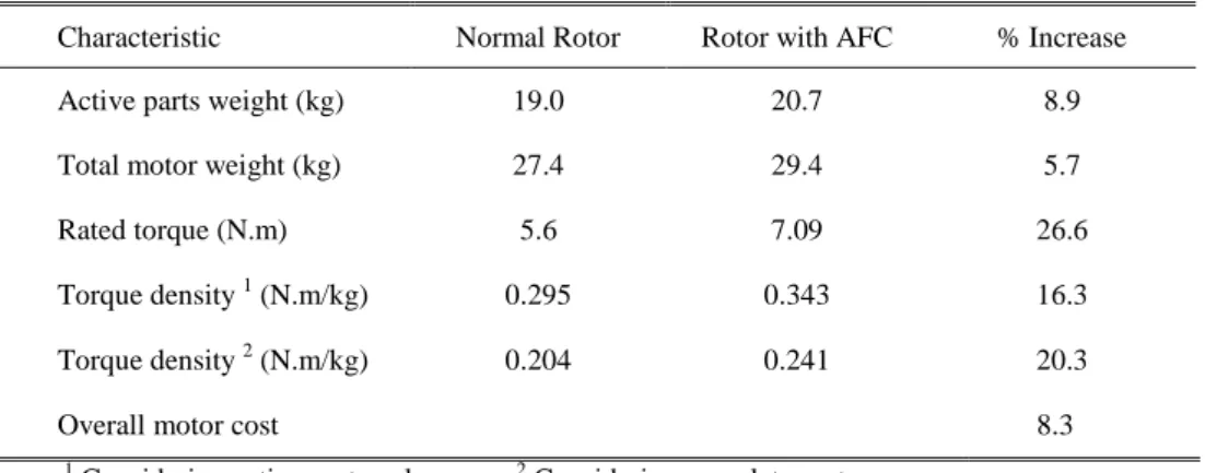
TABLE III MOTOR WEIGHTS AND SPECIFIC CHARACTERISTICS
Characteristic Normal Rotor Rotor with AFC % Increase
Active parts weight (kg) 19.0 20.7 8.9
Total motor weight (kg) 27.4 29.4 5.7
Rated torque (N.m) 5.6 7.09 26.6
Torque density 1 (N.m/kg) 0.295 0.343 16.3
Torque density 2 (N.m/kg) 0.204 0.241 20.3
Overall motor cost 8.3
1
Considering active parts only 2 Considering complete motor
From Table III it is possible to observe that the absolute values of torque densities are modest2 for a
rare-earth PM motor. This is due to the bulky construction and to the conservative dimensioning of a
TENV machine. It is worth mentioning that, as the main goal of building the prototypes was to
evaluate the effectiveness of AFC concept compared to the conventional topology, their design was
absolutely not optimized with regard to torque and power densities.
Fig. 6 illustrates the internal construction of the stator prototype, partially assembled, showing large
internal empty spaces. This indicates yet a great potential for optimization.
2
Fig. 6. Prototype partially assembled, with rotor inserted in stator bore.
From the airgap flux density it is possible to estimate the electrical and mechanical characteristics
of the motor. The peak value of phase voltage can be calculated as follows:
2
p h g p h
D L
E B f N
p
(10)
where f is the frequency and Nph is the number of turns per phase for the stator winding and Bg was obtained from (6).
The RMS phase voltage of the machine operating as a no-load generator is obtained by integrating
the fundamental component of the Bg distribution along one pole pitch. For the magnetic circuit of the prototype, with uniform airgap along nearly the whole polar pitch, the fundamental component of this
voltage is given by:
4 2
g p h w s k
p h r m s
D L
E B f N K K
p
(11)
where Kw and Ksk, defined in Table II, are used.
In brushless DC motors, the peak value of the static torque can be evaluated by:
2 g a p h
T B L D I N (12)
considering two phases conducting the rated current Ia, and an ideal angle between stator magneto motive force and rotor flux density. The quantities calculated by (3), (6), (10), (11) and (12) for both
rotors are presented in Table IV.
TABLE IV CALCULATED CHARACTERISTICS FOR THE PROTOTYPE
Characteristic ROTOR 1 ROTOR 2 % Increase
Airgap flux density (T) 0.598 0.758
26.8
Peak phase voltage1 (V) 73.30 92.90
RMS phase voltage1 (V) 62.90 79.80
Static torque2 (N.m) 5.60 7.09
1
V. 3DFINITEELEMENTMODELING
In order to verify the effectiveness of the proposed topology to increase the flux, as well as to
validate the analytical methodology presented in Sections III and IV, a finite element simulation in
three dimensions has been carried out with the aid of a commercial finite element package. The
simulation has been performed by using the non-linear Magnetostatic approach, with the only
excitation in the magnetic circuit being provided by the magnets. The laminations of both stator and
rotor iron cores have been taken into account in the simulations through the homogenization
technique [24]-[25].
Fig. 7 shows a view of the meshed finite-element model (only one eighth of the motor is modeled
due to symmetry). The slot skewing was not taken into account in the model, because it doesn’t affect
airgap flux density values, it only affects induced voltage, which is not object of this simulation.
Fig. 7. Finite element model of the prototype with the proposed topology.
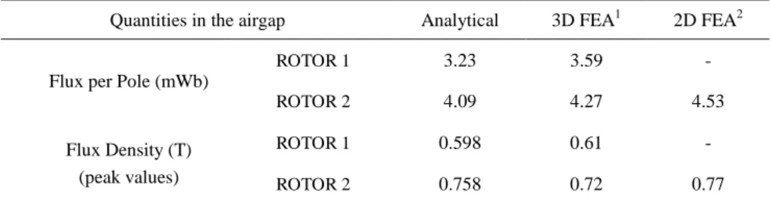
Table V presents the values of flux density and flux per pole for both configurations. The analytical
values were calculated by (3) for ROTOR 1 and by (6) for ROTOR 2. In the case of the FEA, three FE computations were performed. Two of them are in 3D, for ROTOR-1 and ROTOR-2 configurations, respectively. In these cases the flux per pole was computed by a surface integration of the airgap flux
density, as follows:
4
gˆS
B n d S (13)
where S is the area of a cylindrical surface, placed in the center of the airgap, as illustrated in Fig. 8.
TABLE V ANALYTICAL AND NUMERICAL CALCULATIONS IN THE AIRGAP
Quantities in the airgap Analytical 3D FEA1 2D FEA2
Flux per Pole (mWb)
ROTOR 1 3.23 3.59 -
ROTOR 2 4.09 4.27 4.53
Flux Density (T) (peak values)
ROTOR 1 0.598 0.61 -
ROTOR 2 0.758 0.72 0.77
1
Fig. 8. Airgap surface used to compute the flux per pole.
Although 3D simulations are the more realistic among presented calculations, they are difficult to
perform, requiring access to expensive softwares, and are time-consuming. Analytical calculations
and 2D simulations, on the other hand, are much easier to do, and provide results which are in good
accordance with 3D simulations values, being differences tipically less than 10%, as seen in Table V.
Such differences are not surprising, if one takes into account that these more simple calculations use
equivalent quantities presented in section III.
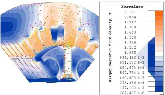
Flux density plots in the end part of the motor for the 3D simulations are shown in Fig. 9. The last
simulation was performed in 2D, with both stator and rotor with the same lengths and the "modified",
fictitious PM, with B’r and μ’rec given by (8) and (9).
Fig. 9. View of the finite element model showing color shades of flux density magnitude (T).
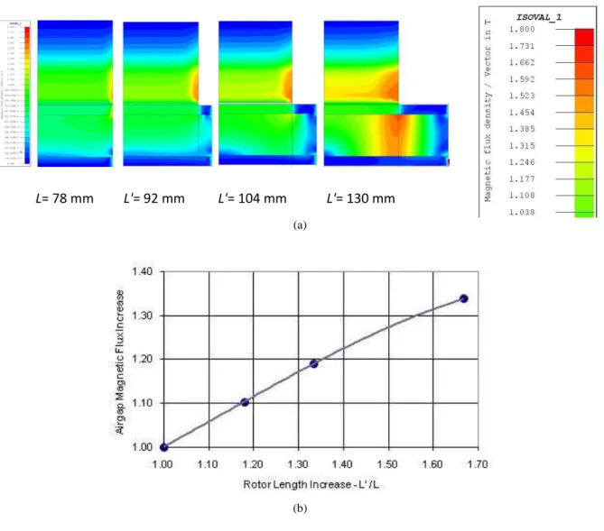
flux per pole as a function of the increase in rotor length, showing the effectiveness of the AFC
technique, as well as its impact in the saturation level. Figs. 10 (a) and (b) show the increase in the
flux per pole for various rotor lengths. This sensitivity analysis can be used to estimate the maximum
increase in rotor length that is allowed for a given magnetic configuration. As can be seen in Fig. 10,
it is clear the effect of magnetic saturation for rotor lengths above 50% longer than the stator length in
the prototype geometry.
Fig. 10. Effect of increased rotor length in the saturation level of AFC motor. (a) Axial views of AFC motor with color sha-des of flux density magnitude, showing increasing saturation levels (the cross-section is along the longitudinal axis in the part viewed in Fig. 9; at right, enlarged view of upper portion of color scale). (b) Increase in flux per pole as a function of
rotor extension.
It is possible to observe also in Fig. 10 (a), that some stray flux originated from the rotor extended
region increases the flux density at the extremities of stator tooth, with more iron losses in that
localized parts.
Fig. 11 presents radial component of airgap flux density for one pole, obtained by 2D simulations,
in cases of ROTOR 1 and ROTOR 2.
L= 78 mm L'= 92 mm L'= 104 mm L'= 130 mm
(a)
Fig. 11. Radial component of flux density distribution in airgap surface used to compute the flux per pole. Length, in horizontal axis, corresponds to arc length along airgap surface.
VI. EXPERIMENTALRESULTS
The prototype motor was submitted to several tests, with both ROTOR 1 and ROTOR 2, allowing a direct comparison of the flux concentration effectiveness. The experimental results are also compared
with those obtained by the analytical procedure proposed in this paper. The machine was tested as a
no-load generator, permitting the acquisition of peak and RMS phase and line voltages, as well as the
induced voltage waveforms. Locked rotor torque tests were also performed, to evaluate its
dependence on the angle between stator magneto-motive force and rotor flux axis, as well as the
torque-current characteristic. The torque was measured by locking the shaft against a force transducer
through a lever arm and the angle measurements made by an absolute encoder while two phases were
fed with the rated current. It is worth mentioning that the locked rotor test provides reliable results,
compared to the normal operation with dynamic switching of the phases. The steel bars utilized for
retaining the rotor laminations and that collaborate with flux concentration, are lodged deep in the
rotor and there will virtually be no current induced in that region during phase commutation, with no
effect in dynamic operation.
The waveforms of the induced voltages are depicted in Fig. 12. It is possible to observe some
degree of voltage ripple, especially in ROTOR 2, where the magnetic circuit is more saturated. This could indicate insufficient skew of stator slots.
Line and phase RMS voltages are shown in Fig. 13, as a function of rotor speed, measured by a
true-RMS voltmeter. The torque-angle characteristic measured with constant rated current is
presented in Fig. 14 (a). Operating as brushless DC motor, the commutation of the phases may ideally
occur at an angle near 45° in a four-pole motor. The distortion of the curves compared with the
theoretical trapezoidal characteristic is due to armature reaction. In Fig. 14 (b) the torque-current
Fig. 12. Waveforms of the induced voltages. (a) Phase voltage. (b) Line voltage. Values measured at half rated speed.
Fig. 13. Phase and line RMS voltages for the prototype operating as a no-load generator at half rated speed. Time (s) 150 100 50 0 50 100 150
0.00 0.01 0.02 0.03 0.04 0.05
P h a se vo lt a g e ( V ) ROTOR 2 ROTOR 1 1050 RPM 35 Hz 0.06 (a) L ine vo lt a g e ( V ) Time (s) 250 200 150 100 50 0 50 100 150 200 250
0.00 0.01 0.02 0.03 0.04 0.05 0.06
ROTOR 2 ROTOR 1 1050 RPM 35 Hz (b) 0 50 100 150 200 250 300
0 500 1000 1500 2000 2500
R M S Li ne a nd ph a se v ol ta ge -V
Speed - RPM
V line ROTOR 2
V line ROTOR 1
V phase ROTOR 2
Fig. 14. Locked-rotor torque characteristics of the prototype. (a) Torque versus mechanical degrees; green line indicates
maximum torque at 55 degrees of angular displacement. (b) Torque versus phase current.
Some measured values, corresponding to half rated speed and rated current are compared with the
calculated values and are presented in Table VI, showing good agreement.
TABLE VI COMPARISON OF MEASURED AND CALCULATED VALUES
Voltage and torque values Calculated % Increase Measured % Increase
Peak phase voltage1 (V)
ROTOR 1 73.3
+26.7%
73.6
+25.7%
ROTOR 2 92.9 92.5
RMS phase voltage1 (V)
ROTOR 1 62.9
+26.9%
63.5
+24.3%
ROTOR 2 79.8 78.9
Static torque (N.m)
ROTOR 1 5.60
+26.8%
5.50
+25.5%
ROTOR 2 7.10 6.90
1
Voltages calculated and measured at half rate speed (1050 RPM).
0 1 2 3 4 5 6 7 8
0 20 40 80 100
T o rq u e ( N.m )
ROTOR 2 I = 4.2 A
ROTOR 1
60
Angular displacement (mechanical degrees) (a) T o rq u e ( N.m ) 0 2 4 6 8 10 12
0 1 2 3 4 5 6 7
Current (A) = 45°
ROTOR 1
ROTOR 2
(b)
A remarkable fact to be observed is that the measured values obtained for ROTOR 2, are in average 25.1% higher, when compared to ROTOR 1, a very close agreement with the increase predicted by the theoretical procedure described in section IV for the AFC technique, namely 26.8%.
The effect of the AFC technique in the motor efficiency at rated load has not yet been verified by
measurements. Nevertheless, calculations show a slight increase in efficiency, as indicated in Table
VII. As expected, the gain in net torque and hence in rated output power, were achieved with the
original stator winding and phase current. In this manner the Joule losses, which are the most
significant contribution to the overall losses in this kind of machine, are kept unchanged. On the other
hand, although augmented core losses can occur, due to higher flux densities, to saturation and
fringing effects at the corners of stator core, this increase will not jeopardize the gain in efficiency.
Table VII shows the calculated losses and efficiencies for both normal and AFC rotors.
TABLE VII CALCULATED LOSSES AND EFFICIENCY
Component Normal rotor Rotor with AFC
Joule losses @ 100°C (W) 73.0 73.0
Core losses @ 70 Hz (W) 27.6 45.6
Friction losses @ 2100 RPM (W) 8.3 8.3
Stray load losses @ 4.2 A (W) 3.7 3.7
Output power (kW) 1.23 1.56
Efficiency (%) 91.63 92.28
The solid bars, utilized for retaining the sector laminations of the rotor and also as a mean to
conduct axially the accumulated flux from its extended part, seems to have no significant effect on the
motor losses. These bars are deeply installed in the rotor, so the eventual flux pulsation due to tooth
ripple and phase commutation does not completely link these bars circuit. On the other hand, it is
possible to roughly consider these steel bars as a kind of damper winding, similar to that existent in
conventional synchronous machines [19]. As well known, damper windings do not contribute
significantly to the total losses in those machines.
VII. CONCLUSION
The AFC technique was presented and applied to rotors with embedded PMs. A prototype with two
rotors was developed to evaluate its effectiveness. It has been shown that it enables a substantial
increase in the airgap flux density, yielding an overall improvement in motor performance. The
proposed topology consists in using a rotor which is longer than the stator, providing a way to axially
conduct the flux created by the magnets located in the extended rotor portion. The increased magnet
weight and rotor complexity are partially offset by the improvement in the performance of such
In the prototype an increase of 25.1% in the net torque was measured, while the total weight was
increased only by 5.4%, and the total manufacturing cost in industrial scale was increased about 8.3%.
Although the efficiency were not actually measured, the calculated values indicate that the AFC
permits also a slight increase in this characteristic, due to the predominance of the Joule losses in this
type of machine, kept invariant for the same load current.
The experimental results agree well with those obtained by both analytical and numerical methods
and the comparison for the two rotors confirm the AFC effectiveness. Moreover, despite de 3D nature
of the flux paths in this topology, it has been shown that, although very simple, the proposed
analytical procedure yields quite accurate results, compared to the more expensive 3D FEA.
REFERENCES
[1] J. R. Hendershot and T. J .E. Miller, Design of Brushless Permanent-Magnet Motors, Oxford Science Publications, 1994.
[2] T. J. E Miller, Brushless Permanent-Magnet and Reluctance Motor Drives, Clarendon Press, 1993.
[3] A.J. Rix and M.J. Kamper, “Radial-Flux Permanent-Magnet Hub Drives: A Comparison Based on Stator and Rotor Topologies,” IEEE Trans. Ind. Electron., vol. 59, No. 6,pp. 2475-2483, Jun. 2012.
[4] C. Mi, M. Filippa, W. Liu and R. Ma, “Analytical method for predicting the airgap flux of interior-type
permanent-magnet machines,” IEEE Trans. Magnet., Vol. 40, No. 1, 50-58, January 2004.
[5] M. Aydin, S. Huang and T. A. Lipo, “Design, analysis, and control of a hybrid field-controlled axial-flux
permanent-magnet motor,” IEEE Trans. Ind. Electron., vol. 57, No. 1, 78-87, Jan. 2010.
[6] P.B. Reddy, A.M. El Rafaie, K.K. Huh, J.K. Tangudu and T.M. Jahns, “Comparison of Interior and Surface PM Machines Equipped With Fractional-Slot Concentrated Windings for Hybrid Traction Applications,”IEEE Trans. Energy Conv., 2012. Digital Object Identifier 10.1109/TEC.2012.2195316.
[7] G. Pellegrino, A. Vagati, P. Guglielmi and B. Boazzo, “Performance Comparison Between Surface-Mounted and Interior PM Motor Drives for Electric Vehicle Application,”IEEE Trans. Ind. Electron., vol. 59, No. 2, 803-811, Feb. 2012.
[8] K.I. Laskaris and A. G. Kladas, “Internal permanent magnet motor design for electric vehicle drive,” IEEE Trans. Ind. Electron., vol. 57, No. 1, 138-145, Jan. 2010.
[9] R. S. Colby and D. W. Novotny, “Efficient operation of surface-mounted PM synchronous machines,” IEEE Trans. Ind.
Applicat., IA-23, 1048-1054, 1987.
[10] V. B. Honsinger, “The fields and parameters of interior type AC permanent magnet machines,” IEEE Trans. Power
Apparat. Syst., PAS-101, 867-875, 1982.
[11] D. Qin, R. Qu and T. A. Lipo, “A Novel Electric Machine Employing Torque Magnification And Flux Concentration Effects”, Conference Record of the 1999 IEEE Industry Applications Conference. Thirty-Forth IAS Annual Meeting, vol. 1, 132-139, 1999. Digital Object Identifier 10.1109/IAS.1999.799943.
[12] H. Yang et al., “A Flux-Concentrating External-Rotor Switched Flux Hybrid Magnet Memory Machine for Direct-Drive Automotive
Applications”, 2015 IEEE International Conference on Applied Superconductivity and Electromagnetic Devices (ASEMD), 209-201, 2015. Digital Object Identifier 10.1109/ASEMD.2015.7453539.
[13] A. Christen and V. V. Haerri, “Analysis of a Six- and Three-Phase Interior Permanentmagnet Synchronous Machine with Flux
Concentration for an Electrical Bike”, 2014 International Symposium on Power Electronics, Electrical Drives, Automation and Motion, 1251-1255, 2014. Digital Object Identifier 10.1109/SPEEDAM.2014.6871995.
[14] I. E. Chabu, V. C. Silva, S. I. Nabeta, M. A. M. Afonso and J. R. Cardoso, “Axial flux concentration technique applied
to the design of permanent magnet motors: theoretical aspects and their numerical and experimental validation,” in
Conf. Rec. IEMDC’2005 – The IEEE International Electric Machines and Drives Conference, 1988-1994, May 2005. [15]P. Viarouge, M. Lajoie-Mazenc and C. Andrieux, “Design and construction of a brushless permanent-magnet
servomotor for direct-drive application,” IEEE Trans. Ind. Applicat., IA-23, 526-531, 1987.
[16] T. Lipo, M. Aydin, “Field Weakening of Permanent Magnet Machines–Design Approaches”, presented at the 11th EPE
Power Electronics and Motion Control Conf., Riga, Latvia, Sep. 2-4, 2004.
[17]P. Sergeant, F. De Belie, J. Melkebeek, Senior Member, “Rotor Geometry Design of Interior PMSMs With and Without Flux Barriers for More Accurate Sensorless Control,”IEEE Trans. Ind. Electron., vol. 59, No. 6, 2457-2465. Jun. 2012. [18]R. Wrobel et al., “Rotor Design for Sensorless Position Estimation in Permanent-Magnet Machines,”IEEE Trans. Ind.
Electron., vol. 58, No. 9, 3815-3824, Sep. 2011.
[19]L. W. Matsch and J. D. Morgan, Electromagnetic and Electromechanical Machines, Harper & Row Publishers, 1986.
[20] M. Marinescu and N. Marinescu, “New concept of permanent magnet excitation for electrical machines: analytical and
[21] Z. Q. Zhu and D. Howe, “Halbach permanent magnet machines and applications: a review,”Proc. IEE - Electr. Power Appl., Vol. 148, No. 4, 299-308, July 2001.
[22]C. Breton et al., “Influence of machine symmetry on reduction of cogging torque in permanent-magnet brushless
motors,” IEEE Trans. Magnet., vol. 36, 3819 – 3823, 2000.
[23]A. M. El-Rafaie, T. M. Jahns and D. W. Novotny, “Analysis of surface permanent magnet machines with fractional-slot
concentrated windings,” IEEE Trans. Energy Conv., vol. 21, issue 1, 34-43, 2006.
[24]J. P. A. Bastos and G. Quichaud, “3D modelling of a nonlinear anisotropic lamination,” IEEE Trans. Magnet., vol. 21, pp. 2366-2369, 1985.
![Fig. 2. Characteristic curve for the equivalent PM in the magnetic circuit with AFC [14].](https://thumb-eu.123doks.com/thumbv2/123dok_br/18888217.424346/6.892.266.663.131.424/fig-characteristic-curve-equivalent-pm-magnetic-circuit-afc.webp)