www.adv-radio-sci.net/4/41/2006/ © Author(s) 2006. This work is licensed under a Creative Commons License.
Radio Science
A multilevel fast spectral domain algorithm for electromagnetic
analysis of infinite periodic arrays with large unit cells
T. F. Eibert
Institute of Radio Frequency Technology, University of Stuttgart, Germany
Abstract. A multilevel fast spectral domain algorithm (MLFSDA) is introduced for the efficient evaluation of the matrix vector products due to the boundary integral (BI) op-erator within a hybrid finite element - BI (FEBI) method for the analysis of infinite periodic arrays. The MLFSDA utilizes the diagonalization property of the spectral domain (SD) BI representation and handles the large numbers of Floquet modes required for large (with respect to wave-length) periodic unit cells by similar hierarchical techniques as applied in the multilevel fast multipole method/algorithm (MLFMM/MLFMA). With the capability of the MLFSDA to handle very large periodic unit cells, it becomes possible to model finite antennas and scatterers with the infinite periodic array model. For a cavity-backed antenna element and for a semi-finite array of 4 cavity-backed antenna elements in the finite direction, the dependence of the input impedances on the unit cell sizes is investigated and it is found that array res-onances disappear for reasonably large unit cell dimensions. Finally, a semi-finite array of antipodal Vivaldi antenna el-ements is considered and simulation results for infinite pe-riodic, finite, and semi-finite array configurations are com-pared to measured data.
1 Introduction
The infinite periodic array model is still an important ap-proach for analysis and design of large finite arrays. With periodic excitation, the field solution in the array becomes also periodic and Floquet’s theorem can be employed to re-duce the computational domain down to a single array ele-ment (unit cell), thus significantly speeding up analysis and reducing memory requirements. In the context of integral equation (IE) formulations, periodic Green’s functions are constructed, where especially spectral domain (SD)
repre-Correspondence to:T. F. Eibert ([email protected])
sentations amenable to multilayered configurations are used (Mittra, 1988; Aroudaki et al., 1995). Arbitrarily inhomo-geneos array elements can be modelled by the hybrid finite element - boundary integral (FEBI) technique (McGrath and Pyati, 1994; Lucas and Fontana, 1995; Eibert et al., 1999, 2000, 2003). Most approaches work with simple half-space Green’s functions in SD (McGrath and Pyati, 1994; Lucas and Fontana, 1995), whereas a spatial domain Green’s func-tion computed via the Ewald transformafunc-tion is used in Eibert et al. (1999). Also, the SD half-space Green’s function has been extended to multilayer configurations above and below the FE mesh in Eibert et al. (2003). The approach in Eibert et al. (2000, 2003) evaluates the SD BI very efficiently by a so-called fast spectral domain algorithm (FSDA), but the approach works efficiently only for relatively small unit cell dimensions (with respect to wavelength), since the necessary Floquet mode numbers increase with the size of the pertinent unit cells.
In non-periodic IE and FEBI approaches, the use of fast integral solvers such as the fast multipole method (FMM) and its multilevel versions (MLFMM/MLFMA) (Chew et al., 2001) or the adaptive integral method (AIM) (Bleszynski et al., 1996) (similarly pre-corrected FFT methods Gedney et al., 2003) have become standard over the past years. Peri-odic IE and FEBI formulations can also be accelerated by fast integral methods. However, large problems with large unit cells require to work with large numbers of Floquet modes (or other types of series terms in spatial domain or mixed spa-tial/spectral representations (Ewald transformation)) and this leads to considerably increasing computational effort, even with the use of conventional fast integral methods.
PBC PBC
BI
BI
FE
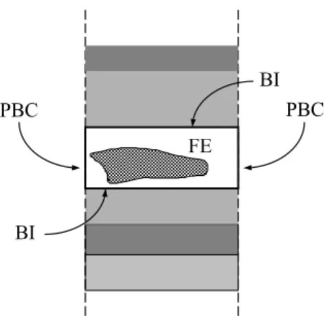
Fig. 1. Cross section of array unit cell with indication of BI and periodic boundary condition (PBC) surfaces.
as employed for FMM and MLFMM/MLFMA. Compared to MLFMM/MLFMA, MLFSDA does not need any near-coupling corrections and all interactions are computed on the coarsest level with only one group. For the considered peri-odic problems, the summation over the Floquet wavenum-bers represents an exact integration rule and also the trans-lation operator evolves directly from the SD representation. In this paper, MLFSDA is employed to accelerate a FEBI technique working with tetrahedral volume and triangular BI elements.
With MLFSDA, unit cells with dimensions of many wave-lengths can be efficiently handled. Thus, it is possible to model multilayer FSS with dissimilar periodicities by the su-percell approach, where a period common to all individual layers is defined and several array elements in the various layers are placed in the computational unit cell. This ap-proach is probably not as efficient as the cascading technique in Ma et al. (2005), but has increased modelling flexibility.
With the capability to handle large unit cells, it becomes possible to place entire finite configurations in a periodic unit cell, which is large enough to decouple the periodic images. Thus, the advantages of the periodic modelling approach (Floquet mode series instead of SD integral) can also be used to compute finite configurations such as finite antenna arrays. The paper is organized as follows. After presenting some basic equations, the MLFSDA technique and the modelling of finite and semi-finite configurations are discussed. In the results section, the transmission coefficient of an 8-layer FSS with dissimilar periodicities is computed and compared to measured data. For the examples of a cavity-backed patch antenna element and a corresponding quadruple patch array, it is investigated which unit cell sizes are necessary to de-couple the periodic images in finite and semi-finite configu-rations, respectively. Finally, a semi-finite array of antipodal Vivaldi antenna elements is investigated.
2 Formulation
2.1 Hybrid FEBI formulation
The hybrid FEBI formulation for infinite periodic array con-figurations employing Floquet’s theorem to reduce the prob-lem to a single unit cell of the array (see Fig. 1) can be found in many references such as McGrath and Pyati (1994); Lucas and Fontana (1995); Eibert et al. (1999, 2003). The period-icity in thexy–plane is defined by the lattice vectorsρa,ρb via the shifting relation
ρmn=mρa+nρb, r =ρ+zzˆ=xxˆ+yyˆ +zzˆ, (1) wheremandnare integers. Assuming the periodicity con-ditions given in Eibert et al. (1999), electromagnetic analy-sis can be carried out by enforcing stationarity of a standard FE functional in terms of the electric field intensityE with BI termination for the FE portion of the unit cell, shown in Fig. 1.
2.2 Multilevel fast spectral domain algorithm
In a standard implementation of the hybrid FEBI method, the BI contribution results in fully populated matrix blocks for the unknowns in the top and bottom BI surfaces and therefore it is desirable to evaluate the BI expression in an alternative manner. It is well known that the standard SD formulation di-agonalizes the BI operator and this property was already uti-lized for the formulation of an FSDA in Eibert et al. (2000). In this section, an MLFSDA is derived which allows very fast evaluation of the BI contributions during the computation of matrix-vector products in an iterative equation solver, even for large unit cells.
We start with the SD representation of the spatial Green’s function in the BI
−
Gp(ρ,ρ′)= Z
kx
Z
ky ˜ −
Gp(kx, ky)
×e−j kx(x−x′)e−j ky(y−y′)dk
xdky, (2)
where
˜ −
Gp(kx, ky)= 1 A
∞
X
p=−∞ ∞
X
q=−∞ ˜ −
G(kx, ky) δ(kt−ktpq) (3)
in the case of an infinite periodic array problem with
A= |ρa×ρb|,kt =kxxˆ+kyy,ˆ ktpq
=kt00+ 2π
A
p(ρb× ˆz)+q(zˆ×ρa),
and ˜
−
Gthe corresponding non-periodic SD Green’s function (see Eibert et al., 1999, 2003) and introduce the decomposi-tion
based on a regular grouping of the basis functions in the BI surfaces. ρg is the group center close to observation point ρ and ρ′g is the group center close to the source point ρ′. Substituting these expressions into the discretized BI contri-bution (e.g. see Eibert et al., 1999) gives
ZZ
S
bm(ρ)· ZZ
S
−
Gp(ρ,ρ′)·bn(ρ′) ds′ds
=
Z
kx
Z
ky ˜
b∗m(kx, ky)·
−
Tmg,ng(kx, ky)· ˜bn(kx, ky) dkxdky (5)
with
˜
bn(kx, ky)= ZZ
S
bn(ρ)ej kx(x−xng)ej ky(y−yng)ds (6)
and the corresponding translation operator
−
Tmg,ng(kx, ky)= ˜ −
Gp(kx, ky)
×e−j kx(xmg−xng)e−j ky(ymg−yng). (7)
Also, bn are the usual Rao-Wilton-Glisson basis functions used to descretize the BI. Equation (5) has the same structure as diagonalized FMM representations (Chew et al., 2001), except that the FMM integration over the Ewald sphere is replaced by SD lateral wavenumber integration, i.e. a trun-cated Floquet mode series in the case of the considered in-finite periodic problem (see Eq, (3)). Thus, by applying the same principles as done in FMM or MLFMM/MLFMA, fast and multilevel fast spectral domain algorithms (FSDAs and MLFSDAs) can be realized to evaluate the BI. However, some important differences are observed. Most importantly, the translation operator in Eq. (5) is known analytically and the whole representation Eq. (5) is exact for all interactions, including near- and self-terms. Moreover, for infinite peri-odic problems the integration rule for the computation of the SD integral in Eq. (5) is also exactly given by the Floquet mode representation of the periodic Green’s function (see Eq. (3)). Consequently, a particular error analysis is not nec-essary for FSDA and MLFSDA, since the algorithms give the same results as conventional SD implementations. In MLFSDA, we must only guarantee that the required inter-polation and anterinter-polation steps are carried out without in-troducing additional errors.
FSDA has already been presented in Eibert et al. (2000). Due to the exact validity of Eq. (5), this algorithm does not work with any grouping and computes all interactions among all basis functions at once. This algorithm is well suited for periodic problems with small unit cells, however, becomes inefficient for large unit cells, where an increasing number of Floquet modes is needed. In MLFSDA, large unit cells are covered by a regular square grid of groups and a hierarchical grouping structure is introduced. Since FSDA and MLFSDA do not suffer from low-frequency break-down, the size of the
BI
BI
FE
metal metal
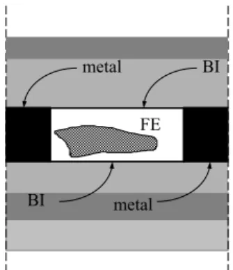
Fig. 2. Cross section of array unit cell for finite array modelling with indication of BI surfaces.
groups on the finest level can be chosen on the same order as the sizes of the discretization subdomains. On higher lev-els, lower level groups are combined until there is only one group on the coarsest levelL. All interactions according to Eq. (5) are computed for the single group on the coarsest level, where the SD sample density is chosen according to the size of this group. One level below, every other sample is left out and so on until the finest level is reached. The sam-pling density on the lower levels is determined by the sizes of the groups on these levels. The sample densities on the vari-ous levels are determined according to the Shannon sampling theorem, where sufficient oversampling must be provided for the interpolation and anterpolation procedures to work.
2.3 Computation of finite and semi-finite configurations by increasing the infinite array period
0 1 2 3 4 5 6 7 8 9 10 0
0.1 0.2 0.3 0.4 0.5 0.6 0.7 0.8 0.9 1
FEBI supercell MoM Aroudaki measured
Frequency in THz
Fie
ld
Transm
is
sion
h/µm g/µm 7.8
7.8
7.8 7.8
7.8 7.8
5 3
5 3
9 6
10 7 10 7
7.8 9 6
6 4
6 4
7.8
7.8
g
c
Fig. 3. Near-infrared 8-layer low-pass FSS with dissimilar peri-odicities,εr=2.31, tanδ=0.035 in FEBI computations, incidence angle 30owith respect to normal, power average of TE and TM.
8.7 mm
20
.0
mm
8.7 mm 16.0 mm
4.4 mm
7.5 mm
εεεεr=2.2-j0.0009
2.6 mm 1.6 mm
x y
Fig. 4.Cavity-backed patch antenna element.
3 Results
The first example is the near-infrared 8-layer FSS with dis-similar periodicities depicted in Fig. 3 and already consid-ered in Aroudaki et al. (1995). For a valid infinite periodic model, the supercell approach must be applied for this prob-lem. The dimensions of the used (smallest) supercell are 90µm by 90µm resulting in up to 18 by 18 patch elements in the upper two layers.
Unfortunately, material losses and fabrication tolerances are not very well known for this FSS. Our FEBI-MLFSDA computations were performed for a dielectric substrate with εr=2.31−j0.08. A truncated Floquet mode series rang-ing from –7 to 7 was used for the representation of the basis function radiation patterns on the finest level and the Floquet mode series representing the Green’s function on the coarsest level ranged from –53 to 53. The discretization model con-sisted of about 3.6 Mio volume unknowns including 20223 BI unknowns. The utilized RAM was about 2.8 GByte
in-8 8.5 9 9.5 10 10.5 11 11.5 12
-50 0 50 100 150 200 250
uc = 64 cav uc = 16 cav uc = 4 cav uc = cav finite
Frequency in GHz
Inpu
t i
m
p
e
dan
c
e
in
Ohm
real
imag
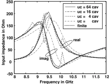
Fig. 5. Input impedance of cavity-backed patch antenna element according to Fig. 4 for infinite periodic array configurations with increasing unit cell dimensions.
cluding about 1.8 GByte for storing the search vectors in the GMRES solver. Field transmission results are given in Fig. 3 and compared to measured results from Aroudaki et al. (1995) and approximate MoM results from Aroudaki et al. (1995), obtained using only one patch in every layer. Es-pecially near the passband edge of the low-pass, our FEBI-MLFSDA supercell results capture the measured behavior more accurately.
The next problem is intended to demonstrate the feasibil-ity of the approach discussed in Sect. 2.3 for the treatment of finite configurations. A simple cavity-backed patch antenna element excited by a probe current as depicted in Fig. 4 is considered. Reference computations were carried out by a 3-D hybrid FEBI code for finite problems, where the cavity-backed patch antenna element was placed in a thick finite metallic ground plane of size 160 mm by 200 mm with height 5 mm. Infinite periodic array computations with the FEBI-MLFSDA code were performed for equally increasing unit cell sizes in the two array dimensions in order to reduce the coupling between the unit cell patch and its periodic im-ages. The input impedance results in Fig. 5 contain clearly visible array resonances for unit cell sidelengths (uc) of 4 and 16 times the cavity sidelengths (cav), but the curves for uc=64 cav do not show anymore obstruction by array res-onances and agree pretty well with the finite ground plane reference results. When the unit cell has the same size as the cavity, the input impedance is also smooth but shows a no-ticeable frequency shift compared to the finite ground plane results. Due to anterpolation of the translation operator in the setup phase, the sample density required on the coarsest level could be kept very small (-6 to +6), no matter how large the unit cell was chosen.
ele-UC = 16 Cav
8 8.5 9 9.5 10 10.5 11 11.5 12
-50 0 50 100 150 200
Frequency in GHz
Inpu
t i
m
p
e
dan
c
e
in
Ohm
Real
Imag
Patch 1 Patch 2 Patch 3 Patch 4
Fig. 6.Input impedances of finite by infinite patch array (4 elements in finite direction) consisting of patch elements according to Fig. 4 obtained with infinite periodic array model with a unit cell 16 times larger than the size of the array in the finite direction.
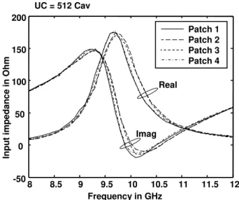
ments according to Fig. 4 in the finite direction is considered. In the infiniteydirection, the patch elements are separated by metallic walls, whereas no metallic walls are present in the finitex direction. Figs. 6 and 7 show the input impedances of the 4 patch elements within the unit cell chosen for the infinite periodic FEBI-MLFSDA computations. The results in Fig. 6 computed with a periodic unit cell sidelength (uc) of 16 times the size of the array in the finite direction are clearly influenced by array resonances due to the periodic images in the computational model. However, after increas-ing the sidelength of the periodic unit cell to 512 times the array size in the finite direction, no more array resonances can be observed in the input impedance results in Fig. 7.
The final example is a semi-finite phased-array antenna of antipodal Vivaldi elements as illustrated in Fig. 8 and discussed in Wilden et al. (2004). The array consists of 8 equally-fed elements on one substrate in the finite direction and up to 256 active elements in the other direction (peri-odic boundaries indicated by dashed lines in the figure). The advantage of the antipodal Vivaldi elements is that they can be fed by microstrip lines. However, a 180◦ phase shift is required between neighboring feed ports. The fabricated an-tenna elements are fed by 1 to 8 power dividers, where the necessary phase shifts are realized by rat-race couplers. In our simulations, each Vivaldi element was fed by a short piece of coaxial line (excited by impressed line currents in the FE mesh) and forward and backward travelling waves on the coax line were extracted by the matrix pencil method in order to determine the pertinentS parameters. First simu-lations were performed for a double element of the antipo-dal Vivaldi radiators. Figure 9 shows simulation results for a free-standing double element computed by a hybrid FEBI
8 8.5 9 9.5 10 10.5 11 11.5 12
-50 0 50 100 150 200
Patch 1 Patch 2 Patch 3 Patch 4 UC = 512 Cav
Real
Imag
Frequency in GHz
Inpu
t i
m
p
e
dan
c
e
in
Ohm
Fig. 7.Input impedances of finite by infinite patch array (4 elements in finite direction) consisting of patch elements according to Fig. 4 obtained with infinite periodic array model with a unit cell 512 times larger than the size of the array in the finite direction.
78
16
.6
18.5 Side view
Top view
Fig. 8. Front (black) and rear (dark grey) side metallizations of 8-element column of antipodal Vivaldi 8-elements. The dashed lines in the top view represent the periodic boundaries, the through lines at left and right sides indicate the electric boundaries in the FE do-main for the semi-finite simulations (dimensions in mm, substrate: Rogers Duroid,εr=2.2, 0.5 mm thick).
code for finite configurations and compares it to the passive reflection coefficient directly measured at the input of a mid-dle element of an 8-element column, where the remaining elements were terminated by 50plugs. The agreement of simulated and mesured results is very reasonable.
6 7 8 9 10 11 12 13 14 -30
-25 -20 -15 -10 -5
0
FEBI finite Measured passive
Frequency in GHz
Reflec
tio
n
in
dB
Fig. 9.Simulated and measured reflection coefficients for antipodal Vivaldi antenna element.
6 7 8 9 10 11 12 13 14
-30 -25 -20 -15 -10 -5
0
FEBI infinite per. Measured active
Frequency in GHz
Reflec
tio
n
in
dB
Fig. 10.Simulated and measured reflection coefficients for antipo-dal Vivaldi antenna array.
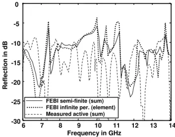
Further FEBI-MLFSDA simulations were performed for the semi-finite array configuration (see Fig. 8). The com-puted reflection coefficients of the 8 elements in the column were combined according to the 1 to 8 power divider used to feed the fabricated antenna. The resulting active reflection coefficient (FEBI semi-finite (sum)) is shown in Fig. 11 and compared to measured results obtained at the input port of the power divider (Measured active (sum)). Again, the cou-pling to 9 columns was considered to determine measured active results. For comparison, also the simulated infinite periodic element results are included. Interesting to note is, that the simulated semi-finite sum results show considerably weaker array resonances than the infinite periodic element results. In the measured active sum results determined at the input port of the power divider, almost no array resonances are found and the active reflection coefficient is below -10 dB
6 7 8 9 10 11 12 13 14
-30 -25 -20 -15 -10 -5 0
FEBI semi-finite (sum) FEBI infinite per. (element) Measured active (sum)
Frequency in GHz
Reflec
tio
n
in
dB
Fig. 11.Simulated and measured reflection coefficients for antipo-dal Vivaldi antenna array.
in most parts of the considered frequency range. The averag-ing among the 8 array elements in the finite array direction obviously suppresses the array resonances.
4 Conclusions
po-tential so speed-up the evaluation of various infinite periodic integral equation operators (e.g. electric field integral equa-tion for planar circuits and antennas in multilayered media).
References
Mittra, R., Chan, C. H., and Cwik, T.: Techniques for Analyz-ing Frequency Selective Surfaces — A Review, Proc. IEEE 76, 1593–1615, 1988.
Aroudaki, H., Hansen, V., Gem¨und, H.-P., and Kreysa, E.: Anal-ysis of Low–Pass Filters Consisting of Multiple Stacked FSS’s of Different Periodicities with Applications in the Submillime-ter Radioastronomy, IEEE Trans. Antennas Propagat., 43, 1486– 1491, 1995.
McGrath, D. T. and Pyati, V. P.: Phased Array Antenna Analysis with the Hybrid Finite Element Method, IEEE Trans. Antennas Propagat., 42, 1625–1630, 1994.
Lucas, E. W. and Fontana, T. W.: A 3-D Hybrid Finite Ele-ment/Boundary Element Method for the Unified Radiation and Scattering Analysis of General Infinite Periodic Arrays, IEEE Trans. Antennas Propagat., 43, 145–153, 1995.
Eibert, T. F., Volakis, J. L., Wilton, D. R., and Jackson, D. R.: Hy-brid FE/BI Modeling of 3-D Doubly Periodic Structures Utiliz-ing Triangular Prismatic Elements and a MPIE Formulation Ac-celerated by the Ewald Transformation, IEEE Trans. Antennas Propagat., 47, 843–850, 1999.
Eibert, T. F. and Volakis, J. L.: Fast Spectral Domain Algorithm for Hybrid Finite Element/Boundary Integral Modeling of Dou-bly Periodic Structures, IEE Proceedings Microwaves, Antennas Propagat., 147, 329–334, 2000.
Eibert, T. F, Erdemli, Y. E., and Volakis, J. L.: Hybrid Finite El-emente - Fast Spectral Domain Multilayer Boundary Integral Modeling of Doubly Periodic Structures, IEEE Trans. Antennas Propagat., 51, 2517–2520, 2003.
Chew, W. C., Jin, J.-M., Michielssen, E., and Song, J.: Fast and Ef-ficient Algorithms in Computational Electromagnetics, Boston: Artech House, 2001.
Bleszynski, E., Bleszynski, M., and Jaroszewicz, T.: AIM: Adap-tive Integral Method Compression Algorithm for Solving Large– Scale Electromagnetic Scattering and Radiation Problems, Radio Science, 31, 1225–1251, 1996.
Gedney, S. D., Zhu, A., Tang, W.-H., Liu, G., and Petre, P.: A fast, high-order quadrature sampled pre-corrected FFT for elec-tromagnetic scattering, Microwave Opt. Technology Letters, 36, 343–349, 2003.
Ma, J.-F., Mittra, R., and Huang, N. T.: Analysis of Multiple FSS Screens of Unequal Periodicity Using an Efficient Cascading Technique, IEEE Trans. Antennas Propagat., 53, 1401–1414, 2005.