Universidade de
Aveiro
2017
Departamento de Engenharia Mecânica
José Miguel
Teixeira Margarido
Desenvolvimento de novos materiais naturais
nanocompósitos para aplicações em engenharia
Universidade de
Aveiro
2017
Departamento de Engenharia Mecânica
José Miguel
Teixeira Margarido
Desenvolvimento de novos materiais naturais
nanocompósitos para aplicações em engenharia
Dissertação apresentada à Universidade de Aveiro para cumprimento dos requisitos necessários à obtenção do grau de Mestre em Engenharia Mecânica, realizada sob a orientação científica de Ricardo José Alves de Sousa, Professor Auxiliar com Agregação no Departamento de Engenharia Mecânica da Universidade de Aveiro e Paula Alexandrina de Aguiar Pereira Marques, equiparada a Investigador Principal no Departamento de Engenharia Mecânica da Universidade de Aveiro.
Apoio financeiro dos projetos
UID/EMS/00481/2013-FCT e
CENTRO- 01-0145-FEDER-022083
O júri / The jury
Presidente / President
Vogais/ Committee
Professora Doutora Mónica Sandra Abrantes de Oliveira Correia
Professor Auxiliar no Departamento de Engenharia Mecânica da Universidade de Aveiro
Professor Doutor Ricardo José Alves de Sousa
Professor Auxiliar com Agregação no Departamento de Engenharia Mecânica da Universidade de Aveiro
Doutor Fábio António Oliveira Fernandes
Bolseiro de Pós-Doutoramento na Escola Superior de Design, Gestão e Tecnologias de Produção de Aveiro Norte
Agradecimentos /
Acknowledgements Esta dissertação de mestrado é a última etapa de um ciclo memorável e
enriquecedor. Contou com apoios que abrilhantaram e tornaram a sua realização possível, aos quais estarei eternamente grato.
Ao professor Ricardo Sousa, pela genuína orientação, otimismo, incentivo e total disponibilidade (que nos dias de hoje, tão rara e valiosa é).
À investigadora Paula Marques e à Susana Pinto, por me receberem e
guiarem no laboratório, pelo conhecimento transmitido, paciência e sugestões. Aos meus amigos, pela camaradagem e a ajuda em todos os momentos. À minha família, em especial aos meus pais, por me terem dado sempre e desde de sempre, todas e as melhores condições. Pelo amparo, incentivo e amor incondicional.
Palavras-chave Cortiça aglomerada; testes mecânicos; absorção de energia; grafeno; oxido de grafeno; nanocompósitos; biopolímeros.
Resumo
A crescente e generalizada consciencialização ambiental obriga cada vez mais a incutir o uso de materiais compatíveis com a sociedade onde nos inserimos. A cortiça é 100% orgânica e sustentável pelo facto de um só sobreiro conseguir produzir cerca de 20 vezes esta matéria prima ao longo do seu ciclo de vida. Também na ótica da reciclagem, todas as sobras das diversas indústrias que usam a cortiça podem fazê-lo, sendo esta triturada e aglomerada posteriormente através de resinas. Porém, é precisamente neste capítulo que residem alguns obstáculos na amizade com a ecologia. O aglomerado de cortiça é bastante apetecível ao nível do preço, quando comparado com o seu estado puro, e uma vez que mantém grande parte das vantagens e competências iniciais, não é de estranhar que seja usado não só em rolhas para vinhos de consumo rápido, mas também em inúmeras aplicações como isolamento térmico e acústico, absorvedor de impactos, peças de vestuário, objetos de design, entre outros. Todavia, a maioria do aglomerado é formado por cola que não é biodegradável, o que vai contra uma das principais bandeiras deste nobre produto português. Pretende-se com esta dissertação caminhar para atenuar esta tendência. Para isso, foi confecionado um aglomerado de cortiça com uma resina 40% biológica e testadas as propriedades mecânicas em testes de compressão quase-estáticos e de impacto.
Ainda no decorrer desta tese, foi criado um nanocompósito de aglomerado de cortiça e grafeno, com o intuito de melhorar as propriedades mecânicas do aglomerado.
De acordo com os resultados alcançados foi possível demonstrar que é possível aprimorar a cortiça em duas frentes diferentes. Por um lado, é possível conceber um aglomerado utilizando resinas mais amigas do ambiente e aplica-lo sem que se percam as suas propriedades essenciais. Por outro, a adição de grafeno como material de reforço foi validada no que diz respeito às propriedades mecânicas do compósito final.
Keywords Agglomerated cork; mechanical tests; energy absorption; graphene; graphene oxide; nanocomposites; biopolymers.
Abstract The increasingly general environmental responsibility progressively encourages
the use of materials compatible with the reality where we live. Cork is 100% organic and sustainable since one cork tree can produce about 20 times this raw material throughout its life cycle. Also from the recycling point of view, all leftovers from the various industries that use cork can put it in practise to create by-products, triturating them and then agglomerating through a binder. However, it is precisely in this chapter that there are some complications in this friendship with ecology. The agglomerate is very attractive due to its price when compared to the pure state, and since it keeps many of the initial advantages and competencies, it is not surprising that it is used not only in corks for fast-consuming wines, but also in numerous applications such as thermal and acoustic insulation, impact absorption, garments, design objects, among others. However, most of the agglomerate is composed by resins that are not biodegradable, which goes directly against one of the main flags of this noble Portuguese product.
It is intended with this dissertation to attenuate this tendency. To this end, a cork agglomerate with a 40% biological resin was prepared and the mechanical properties were tested in quasi-static and impact compression tests.
Also in the course of this thesis, a nanocomposite of agglomerate of cork and graphene was created, in order to improve the mechanical properties of the agglomerate.
According to the results achieved it was possible to demonstrate that cork can be improved on two different fronts. On the one hand, it is possible to design an agglomerate using environmental glues and apply it without losing its essential properties. On the other hand, the addition of graphene as reinforcing material was validated with respect to the mechanical properties of the final composite.
i
Contents
Chapter 1
State of the Art ... 1
1.1
Introduction ... 1
1.2
Cellular Materials – Mechanical properties ... 2
1.3
Cork ... 4
1.3.1 Cork Structure ... 6
1.3.2 The economic importance of cork in Portugal ... 8
1.3.3 Industrial production of cork ... 8
1.3.4 Enhancing cork properties by addition of reinforcement materials ... 9
1.4 Graphene based nanomaterials ... 10
1.4.1 Graphene’s mechanical properties – stiffness ... 12
1.4.2 Graphene’s mechanical properties – strength ... 12
1.4.3 Graphene’s mechanical properties – toughness... 13
1.4.4 Production of Graphene and Graphene Oxide ... 14
1.5 Bio-based polymers ... 18
1.5.1 Natural bio-based polymers ... 21
Chapter 2
Materials and methods ... 27
2.1 Materials ... 27
2.2 Sample production ... 29
2.2.1 Graphene and oxide graphene nanocomposites... 29
2.2.2 Bio-polymer samples ... 31
Chapter 3
Experimental Campaign ... 33
... 34
3.1 Bio-polymer ... 34
3.2 Graphene reinforcement ... 37
Chapter 4
Conclusions ... 44
Bibliography ... 46
Annex A
... 63
ii
List of Figures
Figure 1.1: Honeycomb aluminium / fiberglass / aramid paper / for the aeronautics
industry (Aeroexpo, 2017). ... 2
Figure 1.2: Cellular solid’s stress-strain curve (Ashby, 2006). ... 2
Figure 1.3: Cell bending due to a load structure (Ashby, 2006). ... 3
Figure 1.4: Example of a brittle foam collapse (Ashby, 2006). ... 3
Figure 1.5: Micrographia’s book (Hooke, 1665). ... 4
Figure 1.6: Cork oak and its bark (Amorim, 2017)... 5
Figure 1.7: Boats with the hull in cork (Amorim, 2017).
...5
Figure 1.8: Insole made of cork (Amorim, 2017). ... 6
Figure 1.9 Kitchen utensils made of cork (Amorim, 2017). ... 7
Figure 1.10: Door handles make of cork (Amorim, 2017). ... 7
Figure 1.11: The three main directions of cellular structure of cork (Adapted from Silva et
al. 2005). ... 8
Figure 1.12: Stopper with a cylindrical shape. ... 9
Figure 1.13: Graphene’s sheet (Jameshedberg, 2015). ... 10
Figure 1.14: Graphene oxide structure (Greenoptimistic, 2017). ... 11
Figure 1.15: Graphite structure (Substech, 2017). ... 11
Figure 1.16: Nanoindentation setup in a suspended monolayer graphene membrane and
the respective loading/unloading curve with increasing indentation depth (Lee et al.
2008). ... 12
iii
Figure 1.17: Simulation of graphene absorbing a microbullet (Physicsworld, 2014). ... 13
Figure 1.18: The Paper model (left) and graphene kirigami pyramid (right) (Blees et al.
2015). ... 13
Figure 1.19: Schematic diagram of the mechanism of electrochemical exfoliation of
graphite. The electrodes used were graphite rode and platinum wire mesh for the anode
and cathode, respectively (Parvez et al. 2014). ... 15
Figure 1.20: Simulation of the distribution of strain in different percentages of graphene
coating (Young et al. 2011). ... 18
Figure 1.21: Bio-based polymers production variants (Luc and Eric, 2012)... 19
Figure 1.22: Prediction of the evolution of bio-based polymers’ production from 2011 to
2020 (Mirabal et al. 2013). ... 20
Figure 1.23: Prediction of the evolution of bio-based polymers’ (biomass only) production
from 2011 to 2020 (Mirabal et al. 2013). ... 21
Figure 1.24: Bottle 100% bio based pet exposed by Coca-Cola in World Expo in Milan
(Greenchemicalsblog, 2015). ... 24
Figure 2.1: Small and large cork grains. ... 27
Figure 2.2 PU TDI based binder used in the work. ... 28
Figure 2.3: Biobased synthetic binder used in this work. ... 28
Figure 2.4: GNP used in the present work... 29
Figure 2.5: GO used in the present work... 29
Figure 2.6: Mechanical stirrer used. ... 30
iv
Figure 2.8: Electrical mixer used. ... 30
Figure 2.9: Oven used. ... 30
Figure 2.10: Mould used. ... 31
Figure 2.11: Chemical accelerator and initiator. ... 32
Figure 3.1: Uniaxial quasi-static compression test. ... 34
Figure 3.2: Disintegration of a sample with 10 wt. % of bio binder in the start of the
compression test. ... 35
Figure 3.3: Sample with 15 wt. % of bio binder after a compression test attempt. ... 35
Figure 3.4: Sample with 20 wt. % of bio binder during a uniaxial compression test. ... 36
Figure 3.5: Influence of the bio binder agent and of the grain (equal density 160 kg/m
3). 37
Figure 3.6: Graphene’s campaign- seven different samples tested. ... 38
Figure 3.7: Influence of the GO used as a reinforcement (equal density 160kg/m
3and
grain used). ... 39
Figure 3.8: Sample with 1% GNP during the quasi static uniaxial compression test. ... 40
Figure 3.9: Influence of the GPNs used as a reinforcement (equal density 160kg/m
3and
grain used). ... 41
Figure 3.10: Comparison between samples with 0.1% GNP and 0.1% GO. ... 42
Figure 3.11: Comparison between samples with 0.5% GNP and 0.5% GO. ... 42
v
List of Tables
Table 1: Examples of mechanical properties of graphene/graphite-based polymer
nanocomposites documented. Adapted from T. Kuilla et al. (2010). ... 16
Table 2: Application of PLA and their blends in various fields (adapted from Rabu et al.
2013). ... 21
Table 3: Application of PHAs and their blends in various fields (adapted from Rabu et al.
2013). ... 22
Table 4: Application of PBS and their blends in various fields (adapted from Rabu et al.
2013). ... 23
Table 5: Application of Bio-PE and their blends in various fields (adapted from Rabu et al.
2013). ... 24
Table 6: Application of Cellulose and their blends in various fields (adapted from Rabu et
al. 2013). ... 25
Table 7: Design of experiments with graphene and graphene oxide. ... 31
Table 8: Design of experiments with bio-based polymer... 32
_________________________________________________________________________
José Margarido Master’s degree Dissertation
1
Chapter 1
State of the Art
State of the Art
1.1 Introduction
Cellular materials have been finding increasing curiosity as a solution for many engineering applications. They have a huge potential that is not fully exploited yet, and can be distinguished in categories such as: natural, synthetic, open cell and closed cell (Gibson and Ashby, 1997). They show a mixture of unique properties such as good thermal and acoustic insulation, high stiffness, high energy absorption capacity and high yield stress with respect to their mass. Factors like these make them thought-provoking in many practical uses such as packaging, aerospace industry and for structural applications (Alcântara et al. 2013; Paulino and Teixeira-Dias, 2011).
In order to develop a direction towards an objective it’s important to have the following statement present in mind: “The best material for each application depends on the application itself” (Fernandes et al. 2015). Which, applied to cellular materials, means that there are variations such as strain and mechanical loading that will lead to an optimal choice inside this big family materials. As an example, EPS (expanded polystyrene), that thanks to its price it is considered to be the most widespread of the synthetically group, has an excellent first impact performance. Nevertheless, the material deforms without recovering elastically. The consequence of this circumstance is that it is not viable to use it in road helmets (where, for instance cork can shine), but fits perfectly the packing industry (Shuaeib et al. 2007; Shuaeib et al. 2002; Gilchrist and Mills, 1994).
Many researchers have been attracted by cork mainly due to its capacity to absorbing energy. The variety of new possible applications are abundant and to accomplish that there are already various studies that explored the central aspects of its mechanical aspects (Fortes and Teresa, 1989; Gibson et al. 1981; Pereira et al. 1992; Rosa and Fortes, 1988).
The main objective of this study is to validate a graphene nanocomposite that can show up as an upgrade to agglomerated cork and its mechanical properties and, in the other hand, build an agglomerated cork made of an environmental friend binder.
_________________________________________________________________________
José Margarido Master’s degree Dissertation
2
1.2 Cellular Materials – Mechanical properties
“When modern man builds large load-bearing structures, he uses dense solids: steel, concrete, glass. When nature does the same, she generally uses cellular materials: wood, bone, coral. There must be good reasons for it” (Gibson, 2015).
If there is the desire of having good mechanical properties at low weight, cellular structures are the most natural choice. As previously said, these materials appear oftentimes in nature and have many potential to engineering applications (Fratzl and Weinkamer, 2007). The way they are structured in our reality can serve inclusively as inspiration for our goals. An example of this kind of use by man is some lightweight aerospace components that employ honeycomb-like materials as illustrated in Figure 1.1.
Figure 1.1: Honeycomb aluminium / fiberglass / aramid paper / for the aeronautics industry (Aeroexpo, 2017).
Analysing a cellular material considering its stress-strain curve allow to identify three main regimes as illustrated in Figure 1.2
_________________________________________________________________________
José Margarido Master’s degree Dissertation
3
The onset of plasticity (a), the plateau stress (b) and the densification (c). The first one corresponds to cell edge bending or face stretching (Figure 1.3).
Figure 1.3: Cell bending due to a load structure (Ashby, 2006).
To a small amount of strain,the material deforms in a linear elastic way. Then a period of progressive cell collapse by elastic buckling, starts plastic yielding or brittle crushing called plateau stress. At this time, the material can handle additional deformation and keep the same value of stress, a feature that pleases engineering (Cantor et al. 2008).
It’s also possible to get this phase if the material of the cell wall has its plastic limit immediately next after the elastic limit. In this case, the rupture point is achieved. For instance, one good practical example are the ceramic foams, which because of its fragility to fracture are incapable to return to their initial position after deformation (Figure 1.4).
Figure 1.4: Example of a brittle foam collapse (Ashby, 2006).
_________________________________________________________________________
José Margarido Master’s degree Dissertation
4
Finally, the densification takes place when the cell collapse ends, since the opposite cell walls come into contact.
Often cellular solids have low relative densities and can still handle a considerable strain before densification happens. As long as the strain growths, the cells become more struggled along the loading direction, which increases the toughness/stiffness of the material until tensile failure occurs. There is a small deformation comparing with the values of stress that brutally emerge (Gibson 2005).
1.3 Cork
“I no sooner discerned these (which were indeed the first microscopical pores I have ever saw…) but me thought I had with the discovery of them, perfectly hinted to me the true and intelligible reason for all the phenomena of cork” (Hooke, 1665).
_________________________________________________________________________
José Margarido Master’s degree Dissertation
5
Cork, which is known to be intimately connected to the cell birth, is the bark (Figure 1.6) of the cork oak (Quercus suber L).
Figure 1.6: Cork oak and its bark (Amorim, 2017).
Macroscopically, it is a lightweight, elastic, acoustic absorber, thermal and electrical insulation and nearly impermeable to fluids. The thickness of the cork planks is between 2 and 5 centimetres depending on the years of growth and its conditions. Biologically speaking, it is an undifferentiated cell reproduced by a cellular tissue with capacity for cell division called phellogen. When the cork is extracted, the phellogen dies but it can regenerate due to its meristematic capacity. This process allows to differentiate three types of cork accordingly with the respective generation. The so-called virgin cork takes place after the first harvest which usually happens when it reaches the first 20-30 years of life. Despite the poor quality obtained (which is justify due to its irregular structure, thickness and density and being, for the reasons presented below easy crumbly), it is used to produce agglomerate, applied on shoe soles, gaskets, etc. The second generation (secundeira in Portuguese) does not achieve the best potential of the cork oak. To get there, it is necessary to wait 40-50 years of its lifetime. From that point on the tree can be harvested every 9 years until its death (generally
_________________________________________________________________________
José Margarido Master’s degree Dissertation
6
adding up 100-150 years) and the last type of cork pops up – the gentle cork (amadia in Portuguese) that is used in every purpose that relies on homogeneous cork being the best example the cork stoppers.
In the winter, the phellogenic tissue stops to grow and that can be verified by the dark zones. However, in the beginning of the spring the phellogenium period occurs and it is present until October somewhere around here the harvest should (when necessary) happen.
After being harvested, the water loss through the surface is increased, which reduces the biological activity of the tree (Fortes et al. 2006).
1.3.1 Cork Structure
Cork is fully natural, with unique properties which sets it an unparalleled character. It is lightweight since more than 50% of its volume is air and weights 0,2 g/cm3 meaning that it floats. This feedstock
is not only impermeable to liquids and gases but also presents resistance to moisture (Figure 1.7). It is elastic and compressible with the feature of being a solid that, when compressed on one side, does not increase the volume on the other, due to null Poisson ratio (Figure 1.8).
Figure 1.7: Boats with the hull in cork (Amorim, 2017).
Figure 1.8: Insole made of cork (Amorim, 2017).
Due to cork’s low conductivity to heat, it’s thermal and acoustic insulator (Figure 1.9). Cork is resistant to impact and has a high friction coefficient provided by the honeycomb structure. It is hypoallergenic since does not accumulate dust and, in addition to all of this, it is fully biodegradable, renewable and recyclable, fire retardant and has a great and natural touch (Figure 1.10).
_________________________________________________________________________
José Margarido Master’s degree Dissertation
7
Figure 1.9 Kitchen utensils made of cork (Amorim, 2017).
Figure 1.10: Door handles make of cork (Amorim, 2017).
The chemical composition of this material consists of suberin (45%) which is the main component of the cell wall and the main responsible for its elasticity, lignin (22% insulation compound), polysaccharides (12% a cell wall compound that provides texture), tannins (6% supplies colour) and ceroid (5% and hydrophobic compound with assures the impermeability).
The cork cell is composed of suberin cells in the form of a tiny pentagonal or hexagonal prism and a complex fatty acid filled with an air-like gas, who take up 90% of the space. Commonly it has an average density of 200 kg/m3 (Amorim, 2017).
According to the cellular structure of cork, one can define three main directions in relation to the trunk of the tree (Figure 1.11). The one that is aligned with the radius is designated as radial and the direction along the axis of the tree is called axial. Finally, the direction tangent to the surface of the tree is called tangential.
_________________________________________________________________________
José Margarido Master’s degree Dissertation
8
Figure 1.11: The three main directions of cellular structure of cork (Adapted from Silva et al. 2005).
1.3.2 The economic importance of cork in Portugal
In Portugal, with a bigger market than Porto wine, cork is considered as the most important national product of the primary sector (Gonçalves, 2000). During the year of 2016 this raw material hit all the records with 937,5 million of euros in exports. (Apcor, 2016)
Portugal appears at the forefront of this product, leading not only in the production but also in processing and trading. These results are the natural consequence of having the biggest area of cork tree dehesa in the world, that contains more than 730 thousands of hectares which means 34% of the total area and producing 100 thousand tons of cork (50% of total). It’s also important to note that much of the world’s harvest from other countries ends in Portugal with the purpose of processing. The human value is also very important to highlight, once in this regard, this industry is directly and indirectly responsible for 100 thousand jobs all over the world meanwhile in Portugal forestry has created 9000 jobs alone, but it is known that this number can be scale quickly if is taken into account the process (Apcor, 2015).
1.3.3 Industrial production of cork
The first step after collecting the barks is to pass them through water with the intention of relaxing the cork cell wall producing a straightening of the bent planks. After that the cork has to be boiled to win some flexibility before being worked. In this process the air that exists in the cells expand to configure a stretched uniform cell structure with an increase of its initial volume of 20%. Afterwards it is just a matter of checking if the colour, texture and thickness are regular, since these are characteristics that grant high quality (Thematking, 2005).
_________________________________________________________________________
José Margarido Master’s degree Dissertation
9
In companies like “Grupo Amorim”, the best planks, designed to the best cork stoppers, are fully natural and in order to be manipulated they are cut into strips with the help of a drill, taking out the future stopper with already a cylindrical shape (Figure 1.12). A qualified operator can drill over twenty thousand stoppers a day and the big advantage of doing this manually is that the worker can choose the best places of the strips. After this, the stoppers will still be mechanically verified by robots based on visual quality and all the remains (Amorim, 2015).
Figure 1.12: Stopper with a cylindrical shape.
1.3.4 Enhancing cork properties by addition of reinforcement materials
It is already well-known examples of reinforcement materials that were used to improve cork composites with remarkable results. In fact, as showed in the work of Fernandes et al.(2013) it was possible to increase in 27% the elastic modulus and 47% in the tensile strength by adding coconut fibre if compared with the unreinforced cork-based (50–50) wt.% composite.
Also in the work of Santos et al. (2017), carbon nanostructures were mixed with cork agglomerates but only clearly results were revealed in terms of fire retardancy.
_________________________________________________________________________
José Margarido Master’s degree Dissertation
10
1.4 Graphene based nanomaterials
Graphene is a rising star material which started to be investigated theoretically in Wallace (1947). Since then, and especially after being the main subject of the 2010 Physics Nobel prize, graphene is collecting attention not only from academics but also from industry. This material is the first two-dimensional atomic crystal produced artificially. The reason behind this popularity is connected with noble properties such as stiffness, strength, superior electrical (Cai et al. 2009) and thermal conductivity (5000 𝑊𝑚−1𝐾−1) and chemical tunability that arouse its potential for many applications. It counts with a theoretical specific surface area around 2630 𝑚2𝑔−1 and with high
intrinsic mobility (200 000 𝑐𝑚2𝑠−1 𝑣−1) as presented in this work about electron mobility in suspended graphene (Bolotin et al. 2008) and in this one about electron transport in graphene (Morozov et al. 2008). Graphene’s Young’s modulus is approximately 1TPa meanwhile its optical transmittance is nearly 1 (Zhu et al. 2010).
Graphene is nothing more than a form of carbon (Figure 1.13). This 2D-atomic crystal consists in a layer of sp2 bonded carbon arranged in a hexagonal honeycomb lattice (Zhong et al. 2017).
Figure 1.13: Graphene’s sheet (Jameshedberg, 2015).
Graphene oxide (GO) composition is similar to a sheet of graphene decorated by oxygen and hydrogen and results from the exfoliation of graphite with oxidizers (Figure 1.14). Its popularity is justified due to the cost-effectiveness, the possibility of bulky scale production in trendy areas for GO like membranes, thin films or composites (Hummers and Offeman, 1958).
_________________________________________________________________________
José Margarido Master’s degree Dissertation
11
Figure 1.14: Graphene oxide structure (Greenoptimistic, 2017).
Graphite is a natural mineral mainly present in metamorphic rocks in Asia and America. Its popularity is principally obtained by the pencil lead, the central core of a pencil. Graphite is simply composed by multiple layers of graphene (Figure 1.15) [Substech, 2013].
_________________________________________________________________________
José Margarido Master’s degree Dissertation
12
1.4.1 Graphene’s mechanical properties – stiffness
Stiffness represents the rigidity of a certain material. It’s the measure of the resistance offered by an elastic body to deformation. The value of graphene’s stiffness is outstanding and relies on the stability of the overall hexagonal lattice. In a previous work, Lee et al. (2008) measured the elastic properties and intrinsic breaking strength of free-standing monolayer graphene membranes by nanoindentation in an atomic force microscope. In the following figure (1.16), it is clear graphene’s performance is great when loaded.
Figure 1.16: Nanoindentation setup in a suspended monolayer graphene membrane and the respective loading/unloading curve with increasing indentation depth (Lee et al. 2008).
1.4.2 Graphene’s mechanical properties – strength
In engineering, the definition of strength is the ability to withstand an applied force without failure. The deformation caused is known as strain and it’s common when analysing or characterizing a material to look at its stress-strain curve. In the fact, nobody was able to overcome C.Lee et al. (2008) results that placed the monolayer of graphene as the strongest material known. They registered the value of 42 Nm-1 to its intrinsic strength, which equivalent to 130 GPa. Qin et al. (2016) also
dedicated time and used simulation to study the interlayer shear of mechanical properties of wrinkled multilayer graphene. In their conclusion, due to the geometrical locking effect the properties were expressively increased. An example of geometry of the graphene geometry absorbing a microbullet can be seen in figure 1.17.
_________________________________________________________________________
José Margarido Master’s degree Dissertation
13
Figure 1.17: Simulation of graphene absorbing a microbullet (Physicsworld, 2014).
1.4.3 Graphene’s mechanical properties – toughness
Another very important property in materials science is the toughness. This ability relies on the capability to absorb energy without fracturing. Graphene, as with other mechanical properties, shines in this one that plays between the concepts of strength and ductility. An interesting example was developed by Blees et al. (2015) when, fully inspired by kirigami techniques, they managed to manipulate the graphene’s monolayer into springs in order to improve their initial stretched condition in 240% using a magnetic field (Figure 1.18). This work also suggests that the methods and the philosophy of Kirigami can be useful in areas like sensing, manipulation or nanoscale robotics.
_________________________________________________________________________
José Margarido Master’s degree Dissertation
14
1.4.4 Production of Graphene and Graphene Oxide
The biggest task to solve since the first moment that graphene was first isolated has been to associate a large scale of production with high quality of the final product. Actually, the use of graphene by many industries relies on these two parameters that not always are up to do it in the required way (Phiri et al. 2017). The methods that have been testified are mainly mechanical or chemical. Micromechanical cleavage was the first method to be tested successfully, being then associated to graphene’s birth Geim and Novoselov (2004) found graphene using this technique, also known as “the scotch tape method”. It can be executed without any sophisticated equipment and all it takes is a piece of adhesive tape placed onto then peeled off the surface of graphite. To get a single layer of graphene, an unstained tape is constrained against the graphite flakes adhering to the initial tape. Removing the two tapes cuts the graphite into smaller fragments. Although the high quality provided by this technique, the main issue these days is still industrialization of this process in a bulky scale. Another method to extract the “wonder material” from graphite is to exfoliate in different liquid media using ultrasound (Zhong, 2015). Since it is known that the van der Waals bonds (which are weak compared with covalent bonds that are link the carbon atoms in graphene) hold the layers of graphene collected forming graphite, the liquid phase exfoliation (LPE) operates directly there, overcoming the van der Waals forces bonds. Although LPE has potential in scaling, it faces other kind of problems such as very limited dispersity of the graphene that acts as an unsociable macromolecule. Additionally, the dispersing solvents are not only very expensive but also have either high boiling point or are corrosive (Zhong, 2015). Obtaining graphene via graphite oxide is another procedure that comprises the exfoliation of graphite in an oxidant medium. This process promotes the breakage of the van der Waals bonds introducing oxygen groups on the surface of exfoliated graphite sheet, which helps their diffusion in water. Then graphite oxide goes to a procedure of sonication that finishes with dispersed graphene oxide sheets in water. In order to reach graphene, it’s required to pass through a process of reduction. The work of Dimiev and Tour (2014) is a model example of what was described. Electrochemical exfoliation can be an option too, as related by Parvez et al (2014). In this case, there is an interaction between oxidation and reduction at the anode and cathode with an organic electrolyte. It is applied positive current at the electrodes (graphite and platinum) which will provoke oxidation and consequently the ions that are negatively charged from the electrolyte will be intercalated into graphite layers (Figure 1.19).
_________________________________________________________________________
José Margarido Master’s degree Dissertation
15
Figure 1.19: Schematic diagram of the mechanism of electrochemical exfoliation of graphite. The electrodes used were graphite rode and platinum wire mesh for the anode and cathode, respectively (Parvez et al. 2014).
Polymers based in nanocomposites are attracting general interest, specifically once it was documented and established that exfoliated clays could improve substantially the mechanical component of polymers (Kojima et al. 1993; Okada et al. 1988; Kawasumi 2004). The enhancements reached by these nanohybrid materials can not be achieved by conventional composites (Kuilla 2010). A nanocomposite is a material where at least one of its components is nano-sized, the nanocomponents added to improve the properties of the original material (Okpala 2013). Apart from that, the increase knowledge of the dispersion of graphene carried this specific sector to the limelight. That being said, improvements are tangible at a low filler loading. Graphite, graphene and graphene oxide give distinct possibilities of approach in order to be used to improve the physicochemical characteristics of a composite. Studies have been reported on expanded and exfoliated graphite composites based on several polymers such as epoxy (Yasmin et al. 2006; Debelak et al. 2007), PMMA (Zheng and Wong 2003; Ramanathan et al. 2007), polypropylene (PP) (Kalaitzidou et al. 2007; Wakabayashi et al. 2008), LLDPE (Kim et al. 2009; Kim and Drzal 2010), HDPE (Zheng et al. 2004), Polystyrene (PPS) (Zhao et al. 2007), Poly(vinyl alcohol) (PVA) (Liang et al. 2009; Zhao et al 2010), Thermoplastic Polyurethane (TPU, Lee et al. 2009; Liang et al. 2009), phenylethynyl-terminated polyimide (PETI, Du et al. 2004) and silicone rubber (Cho et al. 2005). Table 1 summarizes the data of the percentage of improvement relative to mechanical properties comparing the nanocomposites with graphite or graphene versus the unreinforced ones.
_________________________________________________________________________
José Margarido Master’s degree Dissertation
16
Table 1: Examples of mechanical properties of graphene/graphite-based polymer nanocomposites documented. Adapted from T. Kuilla et al. (2010).
Matrix Filler type Filler loading (wt.%a, vol.%b)
Process Increase E Increase TS Increase FS Reference Epoxy EG EG EG EG 1a 1a 1a 0.1a Sonification Shear Sonification and shear Solution 8% 11% 15% -20% -7% -6% 87% Yasmin et al. 2006 Yasmin et al. 2006 Yasmin et al.2006 Debelak et al. 2007 PMMA EG GNP 21a 5a Solution Solution 21% 133% Zheng and Wong 2003 (Ramanatha n et al. 2007 PP EG xGnP-1 xGnP-15 Graphite 3b 3b 3b 2.5b Melt Melt Melt Melt 100% 33% 4% -20% -33% Kalaitzidou et al. 2007 Kalaitzidou et al. 2007 Kalaitzidou et al. 2007 (Wakabayas hi et. Al 2008 LLDPE xGnP Parrafin coated xGnP 15a 30 Solution Solution 200% 22% Kim et al. 2009 Kim and Drzal 2010 HDPE EG UG 3a 3a Melt Melt 100% 33% 4% Zheng et al. 2004 Zheng et al. 2004 PPS EG S-EG 4a 4a Melt Melt -20% -33% Zhao et al. 2007 Zhao et al. 2007 PVA GO Graphene 0,7a 1,8b Solution Solution 76% 150% Liang et al. 2009 Zhao et al. 2010
TPU Graphene 5,1b Solution 200% Lee et al. 2009
_________________________________________________________________________
José Margarido Master’s degree Dissertation
17
Note (Abbreviations): E- elastic modulus; TS- tensile strength; FS- flexural strength.
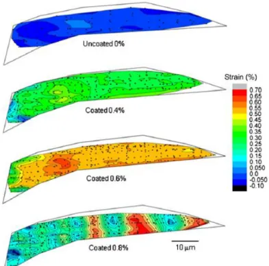
A key point to build an effective composite is linked to the dispersion of the nanomaterial into the host matrix and many studies contemplate that (Texter 2014; Konios 2014; Giudice 2017). With a view to manufacturing industry, few topics should be take into account such as increasing the range of dispersing solvents (preferentially embracing the less toxic and volatile), enhance dispersion stability in terms of concentration, time and temperature and safe handling. All these facts correspond to challenges that belong to the present, having an effective homogeneity as a must. In fact, dispersion of graphene in polymers represents a difficult answer. This can be done by either diffusing the graphene into a co-solvent with the polymer, or diffusing graphene in a monomer and polymerising in situ to produce a composite (Johnson 2015). Young et al. (2011) mixed a single graphene atomic layer with a two layers polymer of poly(methyl methacrylate) beam involving with it and they discovered that the distribution of strain across the graphene was uniform until the levels of matrix strain reached 0.6% but the same did not happen above that value (Figure 1.20). This variation in the strain was verified due to a fragmentation process that develop of cracks in the polymer coating layers caused by a poor level of adhesion between the graphene and polymer layers.
Sulfonated Graphene 1a Solution 75% Liang et al. 2009 PETI EG 5a 10a In situ In situ 39% 42% Du et al. 2004 Cho et al. 2005
_________________________________________________________________________
José Margarido Master’s degree Dissertation
18
Figure 1.20: Simulation of the distribution of strain in different percentages of graphene coating (Young et al. 2011).
1.5 Bio-based polymers
“…Europe must move to an economy that is no longer dependent on oil, we must drive the
transition from a fossil-based to a bio based society with research and innovation as an
engine. It is good for the environment, food and energy security and for Europe’s future…”
EU commissioner for Research, Innovation and Science Máire Geoghegan-Quinn
Polymers are in our world everywhere not only derived by the products that we decide to use but also in nature. Their popularity is undeniable, specially the synthetic ones, mostly used in industry. Besides that, there are also natural polymers that exist in living beings in the shape of proteins, carbohydrates (such as starch, glycogen or cellulose) and nucleic acids (Baird et al. 2014). In terms of their physical response to heating they can be divided in two main groups: i) Thermoplastics that once heated can modify their outline and be manageable above a specific temperature, returning to the initial form when the temperature goes down. These ones are generally easier to be processed, easier to be recycled and for that reason more environmental-friendly. ii) Thermosets also get smoother when heated and can be moulded but the main difference is that they harden permanently
_________________________________________________________________________
José Margarido Master’s degree Dissertation
19
after cooled down. Despite these drawbacks thermosets commonly perform better when is required high heat resistance or even when their mechanical properties are involved.
The plastics sector symbolizes the main application for polymers in our present, having exploded world widely in 1950 (Storz and Vorlop, 2013), reaching a production level of 322 million ton in 2015, being connected to over 1.5 million jobs nowadays (MacArthur, E. 2016). The ones that are more required are synthetized from petroleum, specifically, polyethylene (PE), polypropylene (PP), polystyrene (PS) and poly(ethyleneterephtalate) (PET). As it is understandable by these numbers, it has been created a dangerous connection that drove humanity to be dependent of something that is limited.
As previously said, most of these polymers are hard to be recycled, so it would not solve anything if recycling acts alone. Henry Ford said once that, in order to reduce the fuel consumption in cars, industry should put effort on producing lightweight cars, investing in new materials. In this scenario, a similar solution can occur to inverter this negative and limited trend which is to shift from petroleum-based polymers to bio-based ones (Jeon et al. 2013).
Bio-based polymers are the definition for all the materials that are originated from renewable resources. The interest in bio-based polymers has grew up exponentially in recent years due to the craving for dependency of fossil fuels. The first wave of bio-based polymers was targeted to obtain polymers from agricultural feedstock such as potatoes and corns (starch, cellulose, alginates). After that and thanks to the developments in biotechnology, it was possible to produce polymers close to the popular ones by synthetically constructing monomers from renewable resources as lignocelluloses (starch and cellulose), fatty acids and organic waste using bacterial fermentation, giving rise to PBS, PE, PLA and so on Figure 1.21 (Babu et al. 2013).
_________________________________________________________________________
José Margarido Master’s degree Dissertation
20
A market study made in 2013 (Mirabal et al. 2013) predicted the production of bio-based polymers will triple from 2011 to 2020 reaching a maximum of 12 million tonnes. The most notable variation is seen in bio-based PET. The second one belongs to polymers who are chemically very close to their petrochemical “brothers” such as PE, PP. Finally even PLA and PHA will almost quintuple their capacity until 2020 (Figure 1.22 and Figure 1.23).
_________________________________________________________________________
José Margarido Master’s degree Dissertation
21
Figure 1.23: Prediction of the evolution of bio-based polymers’ (biomass only) production from 2011 to 2020 (Mirabal et al. 2013).
1.5.1 Natural bio-based polymers
Polylactic acid (PLA) has a basic constitutional unit, lactic acid, and belongs to the family of
aliphatic polyesters. It has been commercialized from the beginnings of 1990 although it is known for 150 years (Rabu et al. 2013). PLA is versatile in terms of processing conditions, has a high rigidity and good transparency. The downside stands to its high cost and poor mechanical ductility. The applications of PLA are numerous and mainly dedicated to the hospital area as one can see in the following table.
Table 2: Application of PLA and their blends in various fields (adapted from Rabu et al. 2013).
Polymer Applications Reference
PLGA/PGA Ovine pulmonary valve replacement Williams et al. 2009; Sodiar et al. 1999; Cheng et al. 2009
_________________________________________________________________________
José Margarido Master’s degree Dissertation
22
PLA/chitosan PLA/PLGA/ chitosan PLA
Drug carrier/drug release Jeevitha and Kanchana 2013; Javanth and Vinod 2012; Nagarwal et al. 2010; Chandy et al 2000; Valantin et al. 2003 PLGA and
copolymers
Degradable sutures Rajev 2000
PLA/HA composites
Porous scaffolds for cellular applications Jung-Ju et al. 2012
PLA-CaP and PLGA-CaP
Bone fixation devices, plates, pins, screws, and wires, orthopaedic applications
Huan et al. 2012
PDLLA Coatings on metal implants Schmidmaier et al. 2001 PLA/PLGA Use in cell-based gene therapy for cardiovascular diseases,
muscle tissues, bone and cartilage regeneration, and other treatments of cardiovascular and neurological conditions
Coutu et al. 2009; Kellomaki et al. 2000; Papenburg et al. 2009;
PLA and PLA blends
Packaging films, commodity containers, electrical appliances, mobile phone housings, floor mats, automotive spare parts
Auras et al. 2010
PLA Textile applications Gupta et al. 2007; Avinc and Akbar 2009
Polyhydroxyalkanoate (PHA) also belong to the family of polyesters with the singularity of being
produced by bacterial fermentation. It is chemically defined as linear aliphatic polyester and thanks to its ability to be melted and shaped they can be used directly as plastics without adjustments. The applications for this bio-based polymer are principally relative to cosmetics and medical areas (Voevodina and Kržan, 2013).
Table 3: Application of PHAs and their blends in various fields (adapted from Rabu et al. 2013).
Polymer Applications Reference
P(3HB), P(3HB-co- 3HHX) and blends
Scaffolds, nerve regeneration, soft tissue, artificial oesophagus, drug delivery, skin regeneration, food additive
Yang et al. 2002; Chen et al. 2005; Bavram and Denbas 2008; Tang et al. 2008; Clarinval and Halleux 2005 mcl-PHA/scl-PHA Cardiac tissue engineering, drug delivery, cosmetics, drug
molecules
Sodian et al. 2000; Wang et al. 2003; de Roo et al. 2002; Zhao et al. 2003; Ruth et al 2007
_________________________________________________________________________
José Margarido Master’s degree Dissertation
23
P(4HB) and P(3HO)
Heart valve scaffolds, food additive Valappil et al. 2006; Türesin et al. 2001
P(3HB-co-4HB), P(3HB-co-3HV)
Drug delivery, scaffolds, artificial heart values, patches to repair gastrointestinal tracts, sutures
Williams et al. 1999; Chen et al. 2008; Freier et al. 2002; Kunze et al. 2006; Volova et al. 2003; Philip et al. 2007 PHB, Mirel P103 Commodity applications, shampoo and cosmetic bottles, cups
and food containers
Amass et al. 1998; Walle et al. 2001
Polybutylene succinate (PBS) is also an aliphatic polyester with good tensile and impact strength
but with poor mechanical flexibility that limits the range of its applications. PBS is commercially attractive in areas that involve packaging, hygiene products and others as it’s possible to check in Table 4
Table 4: Application of PBS and their blends in various fields (adapted from Rabu et al. 2013).
Polymer Applications Reference
PBS/PLA blend Packaging films, dishware, fibers, medical materials
Weraporn et al. 2011; Liu et al. 2009; Bhatia et al. 2007; Lee et al. 2006
PBS and blends Drug encapsulation systems Cornelia et al. 2011
PBS/starch Barrier films Jian-Bing et al. 2011 PBS and
copolymers
Industrial applications Jun et al. 2010
PBS ionomers Orthopedic applications Jung et al. 2009
Bio-polyethylene. (Bio-PE) is chemically similar to the most common version of PE (the
fossil-based one), has the same technical properties and it is not biodegradable. Since PE and their variants are the most produced plastics in the world it is imperative to competently produced the bio version. Nowadays Bio-PE manufacturing is based in 3 stages. The first one is the ethanol synthesis by fermentation from sugar. Then it’s necessary to occur chemical dehydration to transform ethanol in ethylene and finally it passes through a reaction of polymerisation giving rise to polyethylene (PE)
_________________________________________________________________________
José Margarido Master’s degree Dissertation
24
[94]. Bio-PE can replace PE in all applications, many of them are already documented as described in Table 5.
Table 5: Application of Bio-PE and their blends in various fields (adapted from Rabu et al. 2013).
Polymer Applications Reference
Bio-PE Plastics bags, milk and water bottles, food packaging films, toys Vona et al. 1965
Bio-PE and blends Agricultural mulch films Kasirajan and Ngouaji 2012
Bio-PET can be obtained from the monomers ethylene glycol and terephthalic acid using bio-based
ethylene glycol. It’s globally used in food, textiles, foils and fibres industry. In 2015, Coca-Cola revealed to the world a 100% bio-based PET bottle in World Expo in Milan (Figure 1.24).
Figure 1.24: Bottle 100% bio based pet exposed by Coca-Cola in World Expo in Milan (Greenchemicalsblog, 2015).
Starch is a unique bio-based polymer produced by green plants for energy storage in structures
known as starch granules, located in plant cells. Starch, the final result of plants’ photosynthesis, is used as a thermoplastic polymer in packing, fishing bait bags and films.
_________________________________________________________________________
José Margarido Master’s degree Dissertation
25
Table 6: Application of Starch and their blends in various fields (adapted from “Current progress on bio-based polymers and their future trends”)
Polymer Applications Reference
Starch Orthopaedic implant devices as bone fillers Ashammakhi and Rokkanen 1997;
Starch/ethylene vinyl alcohol/HA
starch/polycaprolactone blends
Bone replacement/fixation implants, orthopaedic applications
Mainil et al. 1997; Mendes et al. 2001; Marques and Reis 2005
Starch/cellulose acetate blends with methylmethacrylate and acrylic acid
Bone cements Espigares et al. 2002
Modified starch Food applications Jaspreet et al. 2007; Fuentes et al. 2010 Starch derivatives Drug delivery Asha and Martins 2012 Thermoplastic starch Packaging, containers, mulch films, textile sizing
agents, adhesives
Zhao et al. 2008; Maurizio et al. 2005; Ozdemir and Floros 2004; Dave et al. 1999; Guo et al. 2005; Kumbar et al. 2001; Li et al. 2011
Cellulose, the main component of plants’ cell wall, is a crystalline polysaccharide. Its structure is
very similar to the starch, diverging only where glucose units are linked. The production of cellulose resorts mainly on cotton fibers and wood. In terms of mechanical properties, cellulose has a high tensile strength that goes from 62 up to 500 MPa, depending, as it usual in these polymers, on the specific blend composition (Rabu et al. 2013)
Table 7: Application of Cellulose and their blends in various fields (adapted from Rabu et al. 2013).
Polymer Applications Reference
Cellulose esters Membranes for separation Kumano and Fujiwara 2008 Carboxylated methyl cellulose Drug formulations, as binder for drugs, film-coating
agent for drugs, ointment base
Chambin et al. 2004; Obae et al. 1999; Westermark et
_________________________________________________________________________
José Margarido Master’s degree Dissertation
26
al. 1999; Hirosawa et al. 2000
Cellulose acetate fibers Wound dressings Orawan et al. 2008; Abdelrahman and Newton 2011
Hydroxyethyl cellulose Spray for clothes polluted with pollen Hori et al. 2005 Modified celluloses, cellulose
whiskers, microfibrous cellulose
Barrier films, water preservation in food packing Amit and Ragauskas 2009
Cellulose nanofibers Textile applications Zeeshan et al. 2013 Cellulose particles Chromatographic applications, chiral separations Levison 1993; Arshady 1991
Collagen is the most abundant protein in the animal world with more than 27 variations of itself. It’s
a well-known biomaterial used in many cosmetics thanks to its biocompatibility and biodegradability. In engineering, taking advantage of its stretching abilities, it’s used in skin replacement and other biomedical applications (Lee et al. 2001) and in food industry (Gomez-Guille et al. 2011).
_________________________________________________________________________
José Margarido Master’s degree Dissertation
27
Chapter 2
Materials and methods
Materials and methods
2.1 Materials
The c
ork grains used in the experimental campaign were provided by Amorim Cork Composites (ACC) already from previous studies, namely Santos et al. (2017). Two different particle sizes were employed throughout this work: 0.5-1mm and 2-4mm, which from now on will be reported as small and large grains, respectively. An illustrative example can be seen next (Figure 2.1).Small Grain (0.5 to 1mm) Large Grain (3 to 4mm)
Figure 2.1: Small and large cork grains.
One of the binders used was supplied by Flexpur (Ovar, Portugal), and denominated as flexible (Figure 2.2) due to its chemical and physical features. This designation, although poor, was the only information provided by Flexpur and it is based on the comparison between other binders produced by the company. In any case, this company is known for the production of polyurethane (PU) pre-polymers based products. The production of polyurethane is normally related by reacting a di- or polyisocyanete with a polyol. It was also mention by Flexpur that the binder is based on most common used isocyanates, which are the aromatic diisocyanates, toluene diisocyanate (TDI) and methylene diphenyl diisocyanate (MDI). In their work, Santos et al. (2017) also used these binders in the preparation of cork agglomerates. The authors investigated the chemical composition of the binders using a Fourier Transform Infrared Spectroscopy - Attenuated Total Reflectance,
(FTIR-_________________________________________________________________________
José Margarido Master’s degree Dissertation
28
ATR) analysis, and the results indicated that, most probably, the flexible binder is a PU pre-polymers based TDI.
Figure 2.2 PU TDI based binder used in the work.
The bio-binder used (Figure 2.3) in the other experimental campaign was supplied by the Resiquímica – Resinas Químicas, S.A. and belongs to a selection of products denominated ERIS (Eco and Renewable Integrated Solutions). Their compounds are not harmful to nature or to human health and there is a strong motivation to maximize renewable sources in the constituents used. The binder used, ERIS 140, is an unsaturated polyester resin with 54% of renewable raw materials. (Other information concerning ERIS 140 is available in the technical data sheet, present in the annexes section.)
_________________________________________________________________________
José Margarido Master’s degree Dissertation
29
The graphene nanoplates (GNP) powder was provided by Cheap Tubes Inc (USA) and used as given (Figure 2.4), and graphene oxide (GO) (4mg/mL aqueous dispersion) was purchased from Graphenea (Spain). GO was dried by lyophilization and then submitted to a ball milling process in order to obtain small sized particles (Figure 2.5) and gather a more uniform dispersion in the final composite. All other information can be accessed in the data sheets provided in the end.
Figure 2.4: GNP used in the present work.
Figure 2.5: GO used in the present work.
2.2 Sample production
2.2.1 Graphene and oxide graphene nanocomposites
The production of samples consisted in four main steps. First it was weighted the amount of constituents needed to the final composite in an analytical balance (Figure 2.7). Next, the GNP and GO were mingled to the agglomerated cork in plastic bottles and submitted to vigorous mixing for 3 hours (Figure 2.6).
_________________________________________________________________________
José Margarido Master’s degree Dissertation
30
Figure 2.6: Mechanical stirrer used.
Figure 2.7: Balance used.
Then it was added water to the cork part, meanwhile an electric mixer (Figure 2.8) was homogenizing the blend. After 1 minute, the binder was introduced even though the mixer would only stop 5 minutes afterwards. Finally, it was compressed in a press machine until achieving the desired density and heated to 140ºC for two hours in the oven (Figure 2.9), assuring the cure of the polymer in the mould (Figure 2.10).
_________________________________________________________________________
José Margarido Master’s degree Dissertation
31
Figure 2.10: Mould used.
Table 8: Design of experiments for the preparation of cork composites with GNP and GO.
Binder type Binder (wt.%) Density(kg/m3) Grain Size Reinforcement (wt.%)
PU TDI based 10 160 Small(0.5-1mm) 0.1 (GPN) PU TDI based 10 160 Small(0.5-1mm) 0.5 (GPN) PU TDI based 10 160 Small(0.5-1mm) 1 (GPN) PU TDI based 10 160 Small(0.5-1mm) 0.1 (GO) PU TDI based 10 160 Small(0.5-1mm) 0.5 (GO) PU TDI based 10 160 Small(0.5-1mm) 1 (GO)
PU TDI based 10 160 Small(0.5-1mm) 0 (Control test)
2.2.2 Bio-polymer samples
The methodology adopted in this section was very similar to the last described. The main difference relies in the curing process of the binder used in the procedure. While in the of PU pre-polymer binder, the curing process is achieved by the presence of water and high temperatures, the bio-based binder curing involves the presence of an initiator, accelerator and high temperature. A pre-mixture of the bio-binder ERIS 140 with the chemical initiator (2-butanone peroxide) as well as a chemical accelerator (cobalt (II) 2-ethylhexanoate solution) (Figure 2.11) were added to the cork and mixed for 30 seconds. The concentration of chemical initiator and accelerator used were 2 wt. % and 0.4 wt. %, respectively, with respect to the binder. Then the mixture was poured in the mould, pressed and heated for 140ºC, for 2 hours.
_________________________________________________________________________
José Margarido Master’s degree Dissertation
32
Figure 2.11: Chemical accelerator and initiator.
Table 9: Design of experiments with bio-based polymer
Binder type Binder (wt.%) Density(kg/m3) Grain Size
Bio (ERIS 140) 20 160 Small(0.5-1mm) Bio (ERIS 140) 20 160 Large(2-4mm)
_________________________________________________________________________
José Margarido Master’s degree Dissertation
33
Chapter 3
Experimental Campaign
Experimental Campaign
In this work, it was intended to study two main factors in cork agglomerates production. First, the influence of GNP and GO as reinforcement in cork agglomerates using a synthetic PU pre-polymer binder. Secondly, investigate the viability of using a bio-based polyester binder to agglomerate cork granulated materials.
In order to validate both variations of this upgraded agglomerated cork, one with a bio-polymer resin and other one with the reinforcement of GNP and GO, quasi-static compression tests were performed. Variables such as the percentage of the graphene, bio-binder or the grain size used were also explored to pursuit an optimal solution for the composite in question.
The goal of this work focuses primarily practical questions with high chances of being implemented in the real world, or to somehow contribute to the growth of analogue solutions. With this in mind, the mechanical properties were analysed from different angles like the energy density, the plateau-stress, and the strain densification.
To consolidate the argument and to ensure repeatability, every test showed was repeated at least 3 times for each case.
Figures 3.5, 3.7 and 3.9 present the stress-strain curve for the considered cases. Since the samples that were analysed correspond to cellular materials, the mechanical response of the tests was the one expected. At the elastic stage, for a small amount of strain corresponded a slight increase of stress. After that, occurs the so-called plateau stress, in which, for an almost constant applied stress, there is a deformation that goes from 5 to 75%, depending on the specific characteristics examined. This capability is precisely why cellular materials are the key in applications where a stable absorption of the energy is required. Posteriorly, the samples reach densification, known for a huge increase of stress for a small strain increment.
To achieve the quasi-static compression tests it was used a Shimadzu AG50 KN universal test machine. The samples, with 25x25x25 mm, were placed in the center (Figure 3.1) and compressed at a slow strain-rate (0,4 mm/min). The result of the given curves permitted to handle the output in order to have access to the stress-strain curve, and consequently the energy absorbed per volume.
_________________________________________________________________________
José Margarido Master’s degree Dissertation
34
Figure 3.1: Uniaxial quasi-static compression test.
3.1 Bio-polymer
As mentioned before, bio-based biomaterials are a trend that gained popularity by being a necessity of nowadays. Therefore, there are not many documents reporting the use of a bio binder in the preparation of agglomerated cork. As the result, it was hard to predict anything.
Initially, in this dissertation, it was tried to make the composite with the small grain (1-2mm) and 10 wt. % of the binder since it is the percentage used, not only to follow the parameters of the nanocomposites with graphene, but also to add value to what was done in Santos et al. (2017) work, keeping those conditions equal. Nevertheless, once the sample started to be compressed, it collapsed almost immediately, not being possible to get any values to report (Figure 3.2).
_________________________________________________________________________
José Margarido Master’s degree Dissertation
35
Figure 3.2: Disintegration of a sample with 10 wt. % of bio binder in the start of the compression test.
The same happened with a composition of 15 wt. % of bio-binder, as it is possible to be seen in figure 3.3, whereby it was tried 20% (figure 3.4) with success (at least as far as its integrity is concerned).
_________________________________________________________________________
José Margarido Master’s degree Dissertation
36
Figure 3.4: Sample with 20 wt. % of bio binder during a uniaxial compression test.
To test and describe the mechanical response of this resin, as well as to compare with a larger grain, several samples were prepared with the same density (160kg/m3) and using the same methodology
that was previously described.
When comparing the results of bio resins with the synthetic one, it is possible to deduce that the difference between its Young’s modulus is non-existent. However, it is precisely afterwards that the main discrepancy occurs. The plateau stress of the bio binder sample is less pronounced. That is, for a certain value of strain, it corresponds lower stress, which implies considerably less energy absorbed. In the matter of densification stage, the non-bio resin takes place slightly primarily, around 65% in terms of strain, against 75% from bio-composite. Accordingly with what was described by Santos et al. (2017), the most probable reason for that, is that the bio binder corresponds to a more flexible binder than the non-bio one.
It is likely that the behaviour of the sample subjected to a quasi-static compression test relies on the resin used, being that directly related to the properties of the final cork agglomerate.
When comparing the influence of the grain size used, some notes are possible to be taken. In spite of the similar characteristics until the middle of the total strain (around 50%), the larger grain overcomes, in what regards to the mechanical properties, the small one. A higher plateau, for a longer period of strain, makes grains with 2 to 4 mm better energy absorber. This fact can be justified due
_________________________________________________________________________
José Margarido Master’s degree Dissertation
37
to the lack of preponderance of the binder. Since the cork grains are larger, the bio agent has a less important role.
Probably the concentrations of the initiator and accelerator are not the most suitable for this procedure, since it was observed that after mixing, all the components (binder, initiator and accelerator) the mixture turns suddenly to a gel. This make that the mixing process of the binder mixture with granulated cork need to be very fast (only 30 seconds) and a poor mixing process was obtained. The concentrations of initiator and accelerator needed to be optimized in the future.
Figure 3.5: Influence of the bio binder agent and of the grain (equal density 160 kg/m3).
3.2 Graphene reinforcement
To evaluate the effect of the introduction of graphene nanoplates (GNP) or graphene oxide (GO) on the agglomerated cork, it was analysed its behaviour under quasi-static compression tests. The only inconstant term of the equation was the percentage of the reinforcement used, which varied between 0.1, 0.5 and 1 wt. % for both GPN and GO (Figure 3.6). It is also important to refer that the binder used in this case is not the bio one tested previously, but the polyurethane-based one, provided by Flexpur. 0 1 2 3 4 5 6 0 0.2 0.4 0.6 0.8 1 Str e ss (M Pa) Strain PU resin
Bio with large grain Bio with small grain