Specifi cation faced with durability to meet superior level
of performance in structural elements buried
Especifi cação frente à durabilidade para atender nível
superior de desempenho em elementos estruturais
enterrados
a Unisinos, São Leopoldo, Rio Grande do Sul, Brasil.
Received: 09 May 2015 • Accepted: 27 Jan 2016 • Available Online 21 Mar 2016
Abstract
Resumo
The performance standard NBR 15575-1: 2013 [1] states that to achieve the higher level of performance for durability, buried concrete structures must achieve a minimum service life (VUP) of 75 years. However, the NBR 6118:2014 [2] does not specify the minimum project properties for the structure fuli ll this VUP. The objective of this study is to provide recommendations for structural designers to meet higher performance require-ments of NBR 15575:2013 [1] in durability. It was conducted a research of national and international standards and reference publications about the durability and VUP 75 years for structural elements buried. The paper was divided into three parts: (1°) the analysis of the Brazilian and inter-national legal system, as well as reference publications in the area; (2°) discussion of service life prediction models; and (3°) specii cations to meet the superior level of durability of structural elements buried.
Keywords: performance standard, superior performance, service life, burried structures.
A ABNT NBR 15575-1:2013 [1] estabelece que, para atingir o nível de desempenho superior em termos de durabilidade, as estruturas de con-creto armado enterradas devem atender a uma vida útil de projeto (VUP) mínima de 75 anos. Contudo, a norma ABNT NBR 6118:2014 [2] não apresenta recomendações de projeto para que esta VUP seja cumprida. O objetivo deste trabalho é determinar alguns parâmetros projetuais de durabilidade para estas estruturas, visando atender ao requisito de desempenho superior da norma. Para tanto, realizou-se uma pesquisa em normas nacionais e internacionais, além de publicações que remetam a especii cações de projeto para vida útil de 75 anos para elementos es-truturais enterrados. O trabalho dividiu-se em três partes: (1º) a análise do sistema normativo (nacional e internacional) e publicações referência da área; (2º) discussão de modelos teóricos de previsão de vida útil; e (3º) dei nição das especii cações de projeto para elementos estruturais enterrados para o nível superior de desempenho.
Palavras-chave: norma de desempenho, desempenho superior, vida útil de projeto, estruturas enterradas.
F. BOLINA a
[email protected] B.TUTIKIAN a
1. Introduction
According to the performance standard for residential buildings, ABNT NBR 15575-1:2013[1], a structural system must remain safe, stable and eicient throughout its intended service life. Its constit-uents must be designed and built so that, under pre-established use conditions, they keep their functional capability throughout its intended service life, which is 75 years for superior performance. ABNT NBR 15575-1:2013[1] provides that the method for assess-ing the durability of a structure can be to determine whether it com-plies with the requirements set forth in applicable Brazilian stan-dards or, in the absence thereof, speciic international stanstan-dards addressing the matter.
The purpose of this paper is to provide design recommendations for durability, which may be adopted to size and verify the ele-ments in contact with the ground - such as foundations - in order to achieve the ABNT NBR 15575:2013 [1] superior performance level requirement. In such environments, major aggressive agents are chloride ions, sulfate and humidity.
However, the Brazilian standards for structural design and struc-tural system durability mentioned in ABNT NBR 15575-1:2013 [1], ABNT NBR 6118:2014 [2] and ABNT NBR 12655:2015 [3] do not provide recommendations on how to achieve the durability require-ment for buried elerequire-ments, particularly superior service life. Thus, other references should be sought to meet this purpose, both nor-mative and non-nornor-mative.
Therefore, this study was carried out in three stages: (1) analy-sis of the national and international normative system; (2) review
of theoretical models for service life prediction; and (3) deinition and proposal of design recommendations for buried structural el-ements to meet the service life requirement of 75 years. In the irst stage, the applicable Brazilian and international standards are presented, as well as relevant technical publications addressing the minimum design requirements to be in compliance with the standard. In the second stage, these normative design parameters are tested through theoretical models. In the third stage, speciic design speciications are recommended, integrating that used as reference and the results of the service life prediction models.
2. Analysis of the brazilian and
international normative system
2.1 Brazilian standards
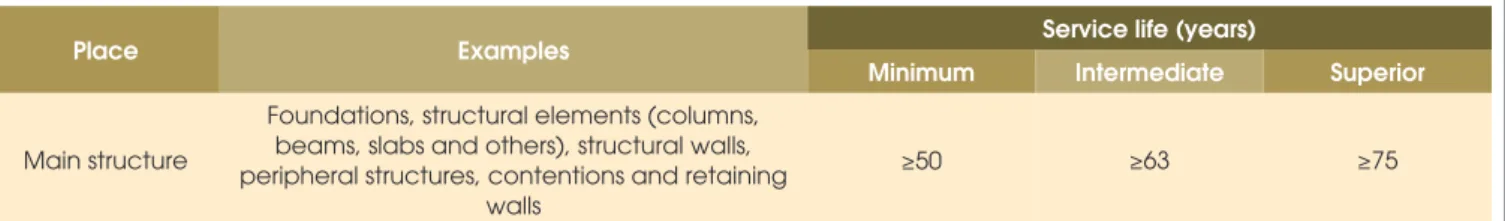
ABNT NBR 15575-1:2013 [1] provides that the design of service life for structural elements of residential buildings must be 50, 63 or 75 years to meet the minimum, intermediate and superior durability levels, respectively, as shown in Table 1.
In reinforced concrete structure designs, environmental aggressive-ness should be classiied according to the criteria used by ABNT NBR 6118:2014 [2], which stipulates that these structures must be designed and built so that, under the environmental conditions es-tablished at the time of design, they remain safe, stable and eicient throughout its intended service life. Table 2 shows the criteria for en-vironmental aggressiveness classiication proposed by this standard.
Table 1 – Service life for minimum, intermediate and superior levels for residential structures
Place Examples Service life (years)
Minimum Intermediate Superior
Main structure
Foundations, structural elements (columns, beams, slabs and others), structural walls, peripheral structures, contentions and retaining
walls
≥50 ≥63 ≥75
Source: ABNT NBR 15575-1:2013, edited by the authors
Table 2 – Environmental aggressiveness classes
Environmental aggressiveness
classes Aggressiveness
General classification of
environmental kind for design Risk of structure deterioration
I Weak Rural Insignificant
Submerged
II Moderate Urban Small
III Strong Marine Big
Industrial
IV Very strong Industrial Elevated
Tidal splash
Depending on the environmental classiication, ABNT NBR 6118:2014 [2] presents recommendations regarding reinforcement cover thickness. This cover thickness is intended to ensure physi-cal, chemical and mechanical protection of the reinforcement, as shown in Table 3.
According ABNT NBR 12655:2015[3], when the requirements pro-vided in ABNT NBR 6118:2014 [2] are met, structural durability will depend on the characteristics of the concrete constituents. There-fore, this standard deines the maximum water/cement ratio, mini-mum compressive strength, and minimini-mum cement consumption, as shown in Table 4. It also shows the ground aggressiveness clas-siication depending on the amount of water-soluble sulfate (SO4) in soil, as shown in Table 5.
The recommendations provided by these standards are assumed
to be for a service life of 50 years. ABNT NBR 8681:2004 [4] deter-mines that for actions that vary over time (variable actions) a refer-ence period is required for them to be equaled or overcome. These values were deined by consensus, having a 25%-35% probability that they will be exceeded during 50 years.
2.2 International standards and reference literature
According to Tutikian, Isaía e Helene (2011) [5], the durability of concrete structures depends on both extrinsic factors (presence of salts, sea spray, acid rain) and intrinsic factors (cement type, wa-ter/cement ratio, additives additions, etc.). This paper focused on the assessment of intrinsic factors required to have a service life of 75 years. The intrinsic factors recommended by the national and
Table 3 – Correspondence between environmental aggressiveness
class and nominal coverings thickness
Kind of
structure Element
Aggressiveness
I II III IV
Nominal covering thickness (mm)
Reinforced concrete
Slab 20 25 35 45
Beam/column 25 30 40 50
Buried structural elements 30 30 40 50
Source: ABNT NBR 6118:2014
Table 4 – Correspondence between environmental aggressiveness
class and concrete quality, for reinforced concrete structures
Concrete Environmental aggressiveness class
I II III IV
Water/cement ratio, in mass ≤0,65 ≤0,60 ≤0,55 ≤0,45
Concrete class (ABNT NBR 8953) ≥C20 ≥C25 ≥C30 ≥C40
Cement consumption for concrete cubic meter, kg/m³ ≥260 ≥280 ≥320 ≥360
Source: ABNT NBR 12655:2015
Table 5 – Requirements for exposed concrete of sulfates solutions
Exposure conditions in function of aggressiveness
Water soluble sulfate (SO4) in soil - %,
in mass
Soluble sulfate (SO4) in water - ppm
Maximum w/c ratio, in mass, for regular aggregate concrete*
Minimum fck (for regular ou light aggregate concrete) - MPa
Weak 0,00 a 0,10 0 a 150 – –
Moderate** 0,10 a 0,20 150 a 1500 0,50 35
Severe*** Above de 0,20 Above de 1500 0,40 40
* Low w/c ratio or high strength could be necessary to obtain low concrete permeability or steel corrosion protection or freezing and thawing; **See water; ***For severe aggressiveness is necessary to use sulfate resistant cements.
international normative system for durability are (a) minimum ce-ment consumption; (b) minimum reinforcece-ment cover thickness; and (c) maximum water/cement ratio. Concrete compressive strength is also mentioned but, as it is related to water/cement ra-tio, it does not require further speciication. The type of cement used could also afect the durability of these structures by chemical deterioration, but it is rarely described in the standards.
2.2.1 Minimum cement consumption
Cement consumption is often related to parameters such as me-chanical strength, durability, luidity, setting time, and others.
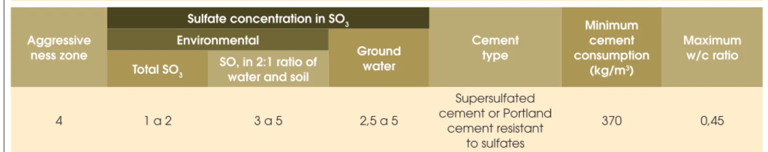
Ac-cording to BRE (2005) [6], penetration of sulfate ions occurs in porous alkaline solutions resulting from cement hydration, leading to damage such as expansion and cracking. By using sulfate-resis-tant cement, the level of tricalcium aluminate is kept at a minimum, thus reducing the impact of such reaction on the structure. Regarding structures embedded in sulfate environments, the recom-mendations provided in IS 456:2000 [7] should be noted. This regula-tion has a qualitative classiicaregula-tion by zone of potentially aggressive en-vironments to concrete structures. The Indian standard mentions buried structures, classifying them under aggressiveness zone number 4. For structures in these circumstances, the standard determines that mini-mum cement consumption should be 370 kg/m³, as shown in Table 6.
Table 6 – Recommendations for high severe aggressiveness zones
Aggressive ness zone
Sulfate concentration in SO3
Cement type
Minimum cement consumption
(kg/m3)
Maximum w/c ratio Environmental
Ground water Total SO3 SO, in 2:1 ratio of
water and soil
4 1 a 2 3 a 5 2,5 a 5
Supersulfated cement or Portland
cement resistant to sulfates
370 0,45
Source: Indian Standard IS -456, adapted by the authors
Table 7 – Specifications to attend service life of 100 years in buried
reinforced or pretensed concrete elements
Corrosion type Exposition condition Cement type
Nominal covering thickness of concrete (mm)
40 45 50 55 60 65 70 75
Chloride (except see water) Salt spray, but without direct contact
I, IIA, IIB-S, SRPC C45/55 0,40;380 C40/50 0,45;360 C35/45 0,50;340 C32/40, 0,55;320 C28/35 0,60;300 C28/35 0,60;300 C28/35 0,60;300 C28/35 0,60;300
IIB-V, IIIA – – C35/45
0,45;360 C32/40, 0,50;340 C28/35 0,55;320 C28/35 0,55;320 C28/35 0,55;320 C28/35 0,55;320
IIIB – – C32/40,
0,45;360 C28/35 0,50;340 C28/35 0,55;320 C28/35 0,55;320 C28/35 0,55;320 C28/35 0,55;320
IVB-V – – C28/35
0,45;360 C25/30 0,50;340 C20/30 0,55;320 C20/30 0,55;320 C20/30 0,55;320 C20/30 0,55;320 Wet, rarely dry
I, IIA, IIB-S,
SRPC – – – – –
C45/55 0,40;380 C40/50 0,40;380 C35/45 0,45;360
IIB-V, IIIA – – – C40/50
0,35;380 C35/45 0,40;380 C32/40, 0,45;360 C28/35 0,50;340 C25/30 0,55;320
IIB, IVB-V – – – C32/40,
0,40;380 C28/35 0,45;360 C25/30 0,50;340 C25/30 0,55;320 C25/30 0,55;320 Wetting and drying cycles
I, IIA, IIB-S,
SRPC – – – – –
C45/55 0,35;380 C40/50 0,40;380 C35/45 0,45;360
IIB-V, IIIA – – – C40/50
0,35;380 C35/45 0,40;380 C32/40, 0,45;360 C28/35 0,50;340 C25/30 0,55;320
IIIB, IVB-V – – – C32/40,
0,40;380 C28/35 0,45;360 C25/30 0,50;340 C25/30 0,50;340 C25/30 0,50;340
BS EN 206-1:2006 [8] recommendations for cement consumption are similar to those provided by IS 456:2000 [7]. Similarly to Brazil-ian regulations, these standards do not have a description about the service life used. For both ACI 318-11:2002 [9] and ABNT NBR 6118:2014 [2], service life is assumed to be 50 years, based on the time of return of the design variable actions. These recommenda-tions are more conservative than those adopted by ABNT NBR 6118:2014 [2] for buried structural elements.
2.2.2 Nominal cover to reinforcement
Concrete cover is used to provide the reinforcement with chemical and physical protection in order to ensure that the superior perfor-mance level is obtained, that is, a minimum service life of 75 years. Table 3, taken from ABNT NBR 6118:2014 [2], speciies the mini-mum reinforcement covers for a service life of 50 years; for more strict criteria, additional information is required.
According to Neville & Brooks [10], it is possible for structures to have a service life of 100 years if speciic nominal covers are opted based on the type and exposure condition of structures, in dition to the concrete strength classiication. This is the principle ad-opted in ABNT NBR 6118:2014 [2] and ABNT NBR 12655:2015 [3]. Within this context, Table 7 shows the BS 8500-1:2006 [11] specii-cations for a service life of 100 years, focusing on chloride ion attack. Thus, for wet and rarely dry conditions in environments poten-tially prone to corrosion by chloride, reinforcement covers should
Figure 1 – Effect of w/c ratio in
chloride penetration
(Source: JAEGERMANN,
1990 apud POLITO, 2006)
Table 8 –ACEC classification for natural soils
Sulfates Ground water pH
ACEC class of soil Design Class
of soil
Water / soil 2:1 ratio (SO4 mg/l)
Ground water (SO4 mg/l)
Sulfates total potential
(SO4 %)
Static water (pH)
Mobile water (pH)
DS-1 < 500 < 400 < 0,24
≥ 2,5 – AC-1s
≥ 2,5 > 5,5 A1-1
≥ 2,5 2,5 - 5,5 AC-2z
DS-2 500 - 1500 400 - 1400 0,24 - 0,6
> 3,5 – AC-1s
– > 5,5 AC-2
2,5 - 3,5 – AC-2s
–
2,5 - 5,5 AC-3zDS-3 1600 - 3000 1500 - 3000 0,7 - 1,2
> 3,5 – AC-2s
– > 5,5 AC-3
2,5 - 3,5 – AC-3s
–
2,5 - 5,5 AC-4DS-4 3100 - 6000 3100 - 6000 1,3 - 2,4
> 3,5 – AC-3s
– > 5,5 AC-4
2,5 - 3,5 – AC-4s
–
2,5 - 5,5 AC-5DS-5 > 6000 > 6000 > 2,4 > 3,5 – AC-4s
2,5 - 3,5 ≥ 2,5 AC-5
be at least 55 mm, with
f
ck of 40 MPa, maximum water/cement ration of 0.40, and minimum cement consumption of 380 kg/m3. BS 8500-1:2006 [11] uses concrete cover, compressive strength,water/cement ratio and cement consumption to ensure struc-tural durability, similarly to ABNT NBR 6118:2014 [2], ABNT NBR 12655:2015 [3] and other international standards.
2.2.3 Water/cement ratio
As the thickness of reinforcement covers, maximum water/cement ratio will also depend on environmental aggressiveness. In order to determine the ratio for a service life of 75 years for buried struc-tures, attack by chloride and sulfate should be considered, as well as soil humidity.
According to CCAA (2009) [12] and Figueiredo (2011) [13], concrete resistance against chloride attack depends on the material poros-ity, particularly size, distribution and interconnectivity of paste pores. This variable is directly proportional to the water/cement ratio. Fig-ure 1 shows the efect of such variable on chloride ion penetration (POLITO, 2006 [14]). Table 8 shows the BS 8500-1:2006[11] specii-cation for maximum water/cement ratio allowed in designs for areas having this type of environmental aggressiveness.
ACI 318-11:2002 [9], similarly to Brazilian standards, does not dis-criminate the intended service life by adopting design parameters (it is assumed to be 50 years), according to ASCE 7-05 (2005) [15]. However, similarly to the Brazilian standard, ACI 318-11:2002[9] adopts an environmental classiication based on aggressiveness. Considering a structure exposed to humidity and external chloride sources (class 2), a maximum water/cement ration of 0.4 is recom-mended, consistent with the BS 8500-1:2006 [11] recommendation. Another hypothesis to be considered when analyzing the durability of buried structures is attack by sulfates in the ground, particu-larly in industrial areas. Mehta & Monteiro (2014) [16] note that magnesium sulfate, sodium and potassium are commonly found in groundwater.
According to Isaia (2011) [17], sulfate attack occurs by chemical reaction of the sulfate ion with the aluminate components of
hard-Table 9 – DC class and APM number for
concrete elements in zones with hydraulic
gradient less than or equal to 5: concrete for
general use in situ
ACEC class of soil
Planned service life
Until 50 years Until 100 years
AC-1s, AC-1 DC-1 DC-1
AC-2s, AC-2 DC-2 DC-2
AC-2z DC-2z DC-2z
AC-3s DC-2 DC-3
AC-3z DC-3z DC-3z
AC-3 DC-2 DC-3
AC-4s DC-3 DC-3
AC-4z DC-4z DC-4z
AC-4 DC-3 DC-4
AC-4ms DC-4m DC-4m
AC-4m DC-4m DC-4m
AC-5z DC-4z + APM3 a DC-4z + APM3 a
AC-5 DC-4 + APM3 a DC-4 + APM3 a
AC-5m AC-4m + APM3 a AC-4m + APM3 a
Source: adapted from BRE Special Digest 1:2005
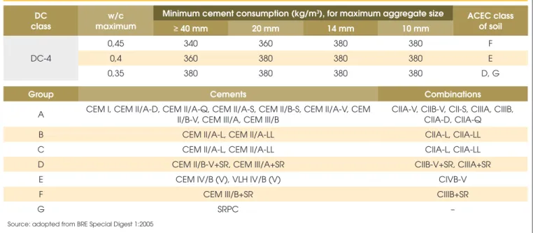
Table 10 – Concrete quality for resistance to chemical attack: concrete for general use in situ
DC class
w/c maximum
Minimum cement consumption (kg/m3), for maximum aggregate size
ACEC class of soil
≥ 40 mm 20 mm 14 mm 10 mm
DC-4
0,45 340 360 380 380 F
0,4 360 380 380 380 E
0,35 380 380 380 380 D, G
Group Cements Combinations
A CEM I, CEM II/A-D, CEM II/A-Q, CEM II/A-S, CEM II/B-S, CEM II/A-V, CEM
II/B-V, CEM III/A, CEM III/B
CIIA-V, CIIB-V, CII-S, CIIIA, CIIIB, CIIA-D, CIIA-Q
B CEM II/A-L, CEM II/A-LL CIIA-L, CIIA-LL
C CEM II/A-L, CEM II/A-LL CIIA-L, CIIA-LL
D CEM II/B-V+SR, CEM III/A+SR CIIB-V+SR, CIIIA+SR
E CEM IV/B (V), VLH IV/B (V) CIVB-V
F CEM III/B+SR CIIIB+SR
G SRPC –
ened concrete. Mehta & Monteiro (2014) [16] argue that concrete degradation can occur as expansion and cracking. Concrete ex-pansion can cause cracking, which increases concrete perme-ability, facilitating the penetration of other aggressive agents in the structural element.
BRE (2005) [6] proposes a methodology to select sulfate-resistant concrete. The starting point is to determine the ACEC (Aggres-sive Chemical Environment for Concrete) class of the ground, as shown in Table 9. This classiication depends on the total potential for sulfate and on the pH of the groundwater. After that it is possible to determine the DC (Design Chemical) class of concrete for a ser-vice life of 100 years (Table 10Erro! A origem da referência não foi encontrada.). With this it is possible to determine the maximum water/cement ratio, cement type and consumption (Table 9). For comparison purposes with the water/cement ratio recommen-dations for chloride attack, the ground aggressiveness classiica-tion is considered to be AC-5, the most severe level condiclassiica-tion of exposure to sulfates. In this class, for a service life of 100 years the concrete class is DC-4. Accordingly, a water/cement ratio of 0.35, 0.4 or 0.45 is recommended (values associated with other concrete characteristics).
2.2.4 Cement type
ABNT NBR 5736:1999 [18] allows adding up to 50% of pozzolan to clinker, calcium sulfate and carbonate material to produce CPIV. Pozzolanic cement, due to the reaction of the pozzolan with the calcium hydroxide produced by cement hydration, has increased durability, because the calcium hydroxide, which is highly soluble and leachable, is combined as hydrated calcium silicate, more re-sistant to aggressive agents. The same occurs with CPIII, which, according to ABNT NBR 5735:1991 [19], is a mixture of clinker, calcium sulfate and carbonate material with 30%-70% of blast-furnace slag.
These types o cement are therefore recommended for applications exposed to lowing water and aggressive environments. They are less permeable, more durable, having higher long-age compres-sive strength as compared to concrete produced from Portland
ce-ment with lower levels of additions. They have lower heat of hydra-tion during the setting period because their reachydra-tions are slower, being recommended for high volume applications such as founda-tion blocks, for example.
Also, the alkali-aggregate reaction, which can cause expansion of the inished structure, is mitigated by adding pozzolan, according to ABNT NBR 15577:2008 [20]. Nagesh (2012) [21] states that ap-plication of this type of cement is recommended for the production of structural elements potentially prone to this kind of attack, such as those in contact with the ground.
ABNT NBR 6118:2014 [2] deines carbon dioxide and chloride ions as the main aggressive agents for concrete structures, and they should be anticipated and prevented in the design and use stage of the building. This standard also refers to attack by leaching pro-cesses and expansion reactions, such as that caused by alkali-ag-gregate and sulfates. In the absence of experimental test values, Medeiros, Andrade e Helene (2011) [22] recommend adopting a guiding speciication, as shown in Table 11 and Table 12, using pozzolanic additives.
Therefore, in order to analyze the durability of buried structures in terms of design, the chemical composition (type) and minimum cement consumption should be assessed, among other factors.
2.3 Service life prediction models
Theoretical models for service life prediction are useful to under-stand the propagation rate of aggressive agents in concrete and to determine the required reinforcement cover and other means of protection, such as reduced water/cement ratio, argue Bolina e Tu-tikian [23]. Interpreting these theoretical models, which are usually developed from experimental tests, helps to understand the rate of chemical deterioration of concrete constituents.
To determine the durability of concrete structures, service life prediction models must be analyzed for chloride ion penetration, which will basically depend on the material porosity and reinforce-ment cover, in the worst scenario, as penetration is rather quick. The most adequate theoretical models are by Helene (1993) [24] and Bob (1996) [25].
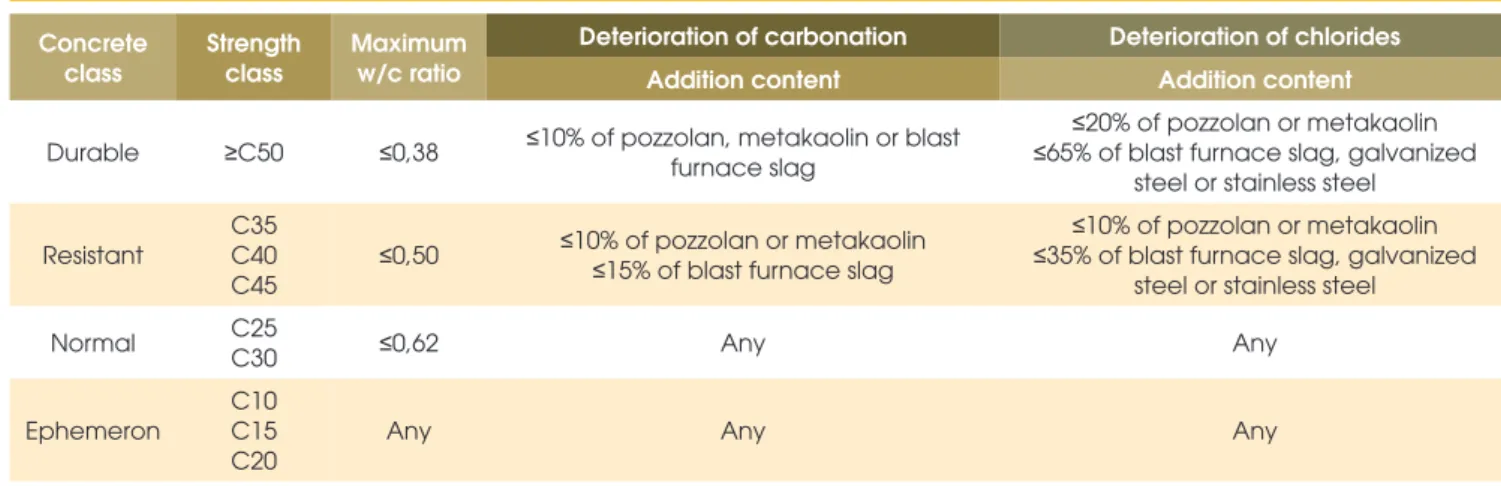
Table 11 – Classification of concrete strength against the risk of reinforcement corrosion
Concrete class
Strength class
Maximum w/c ratio
Deterioration of carbonation Deterioration of chlorides
Addition content Addition content
Durable ≥C50 ≤0,38 ≤10% of pozzolan, metakaolin or blast
furnace slag
≤20% of pozzolan or metakaolin
≤65% of blast furnace slag, galvanized steel or stainless steel
Resistant
C35 C40 C45
≤0,50 ≤10% of pozzolan or metakaolin ≤ 15% of blast furnace slag
≤10% of pozzolan or metakaolin
≤35% of blast furnace slag, galvanized steel or stainless steel
Normal C25
C30 ≤0,62 Any Any
Ephemeron
C10 C15 C20
Any Any Any
2.3.1 Helene (1993) [24]
This model determines the penetration depth of chloride ion ac-cording to equation 1.
(1)
Where t is time, in years, and k is the chloride ion difusion coeicient. Helene (1993) [24] suggests that chloride concentration in a structural element should be expressed in relation to the cement mass (
Cl
cimento), directly inluenced by the chloride concentration in the environment
(
Cl
amb)
. This correlation is expressed in equation 2.(2)
Where
Cl
cimento is cement consumption, in kg/m³, Ab is maximumwater absorption in concrete, expressed in %, and ɣ is the bulk density of concrete, in kg/m³.
2.3.2 Bob (1996) [25]
After veriications based on long-term experiments data, Bob (1996) [26] observed that the modeling of chloride penetration could be expressed by equation 3.
(3)
Where
x
m is the average chloride penetration depth, in millimeters,
fc is the characteristic compressive strength of concrete, in MPa, c is the ixing ability of chlorines, k1 is the inluence of temperature on the model, k2 is the inluence of humidity and d is the ratio be-tween critical concentration and surface concentration of chlorides in the structure.
3. Results and discussion
Based on international standards and reference publications in the area, minimum parameters were proposed to ensure a service life of 75 years for buried structures, reaching the superior level of the Performance Standard. These parameters build on standard rec-ommendations that provide speciications for this kind of structures, such as ACI 318-1:2002 [9], EN 206-1:2000 [8], IS 456:2000 [7], ABNT NBR 15577-1 [26] and BS 8500-1:2006 [11]. These durabil-ity parameters, similarly to ABNT NBR 6118:2014[2], are minimum compressive strength, maximum water/cement ratio, minimum ce-ment consumption, cece-ment type and nominal reinforcece-ment cover. From these prediction models design parameters were derived to yield a service life of 75 years for buried structures in slightly ag-gressive, moderately aggressive and highly aggressive environ-ments, as shown in Table 13. The models of Helene (1993) [24] and Bob (1996) [25] were assessed to ind an average value. As these models represent chloride ion attack, a critical value was obtained for buried elements.
Table 14 shows the design properties to meet such requirement, where all parameters are numerically supported by and in line with national and international references.
Speciications for water/cement ratio followed BS 8500-1:2006 [11]. This standard also provides for variations of water/cement ra-tio and cover, which was not adopted in this paper.
It was used the aggressiveness classiication of Brazilian stan-dards, such as ABNT NBR 12655:2015 [3], and international standards, such as ACI 318-11:2002 [9], EN 206-1:2000 [8] e IS
Table 12 – Classification of concrete strength against the risk of deterioration
by leaching or by formation of expansive compounds
Durable resistant
Strength class
Deterioration of expansion Deterioration of leaching
C3A content in anhydrous cement
Addition content Addition content
Normal ≥ C50 ≤ 5% ≥ 20% of pozzolan or metakaolin ≥ 65% of
blast furnace slag
≥ 20% of pozzolan or metakaolin ≥ 65% of blast furnace slag
Ephemeron
C35 C40 C45
≤ 5% ≥ 10% de pozolana ou metacaulim ≥ 35% of blast furnace slag
≥ 10% of pozzolan or metakaolin ≥ 35% of blast furnace slag
Durable C25
C30 ≤ 8% Any Any
Resistant
C10 C15 C20
Any Any Any
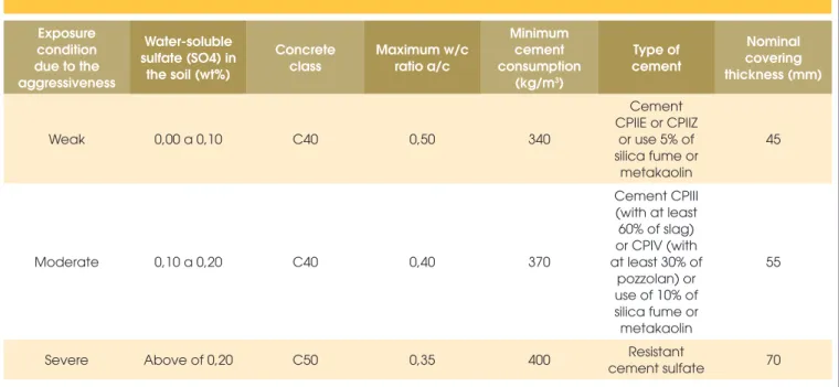
456:2000 [7], where environments are categorized as slightly ag-gressive, moderately aggressive and severely aggressive. It should be noted that for a slightly aggressive class a nominal cover of 45 mm is required, which, according to service life prediction models, will protect the structure for 75 years. If the structure is located in a moderately aggressive environment, nominal cover should be 55 mm. And for severely aggressive environments the speciication if
for nominal cover of 70 mm. Use of ibers or cover reinforcement is recommended when cover exceeds 50 mm (IS 456:2000 [7]).
4. Conclusions
ABNT NBR 15575-2:2013 [1] provides unprecedented durability parameters, not yet seen in Brazil. As it is a performance standard,
Table 13 – Service life prediction model for elements subjected to severe aggression by chlorides,
according (a) Helene (1993) [24] e (b) Bob (1996) [25]
Weak aggressiveness
(a) (b)
C 340 kg/m³
Clsup. 0,0441 % fc 40 MPa
ɣ 2500 k 0,0441 k1 0,75 Cover 36,5 mm
Cenvironmental 0,3 t 75 years k2 1 c+ΔC 46,5 mm
Abh 2 % y 3,309 cm d 1,5
Cover 33,1 c 1
c+ΔC 43,1 mm t 75 years
w
INPUT DATA (gray) INPUT DATA (gray)
Moderate aggressiveness
(a) (b)
C 370 kg/m³
Clsup. 0,059028 % fc 40 MPa
ɣ 2500 k 0,059028 k1 1,25 Cover 45,7 mm
Cenvironmental 0,5 t 75 years k2 1 c+ΔC 55,7 mm
Abh 1,7 % y 4,427083 cm d 1,5
Cover 44,3 c 1
c+ΔC 54,3 mm t 75 years
w
INPUT DATA (gray) INPUT DATA (gray)
Severe aggressiveness
(a) (b)
C 400 kg/m³
Clsup. 0,0781 % fc 50 MPa
ɣ 2500 k 0,0781 k1 1,5 Cover 58,5 mm
Cenvironmental 2,5 t 75 years k2 1 c+ΔC 68,5 mm
Abh 0, 5 % y 5,859 cm d 1,5
Cover 58,6 c 1
c+ΔC 68,6 mm t 75 years
w
it is based on prescriptive rules of the Brazilian normative system; however, it provides no recommendation as to how to comply with the higher performance requirement. For instance, there is a gap on how to achieve superior performance for buried reinforced con-crete structures, such as foundation blocks and stakes. In order to ill this gap, a review of the existing standards in the world and other relevant publications was carried out to support the decision-making. Conirmation through theoretical models for service life prediction was required to validate the comparison. It was conclud-ed that to ensure a service life of 75 years, a buriconclud-ed concrete struc-ture can be made of cement with additions, providing increased durability when in contact with contaminated areas or materials, thus preventing propagation of a potential alkali-aggregate reac-tion. Concrete dosage parameters were also determined in relation to compressive strength, water/cement ratio and cement consump-tion, in addition to nominal cover to steel bars, to ensure a service life of 75 years, superior level of the Performance standard.
5. References
[1] ASSOCIAÇÃO BRASILEIRA DE NORMAS TÉCNICAS. NBR 15575-2: Ediicações habitacionais – Desempenho. Parte 2: Requisitos para os sistemas estruturais. Rio de Ja-neiro, 2013.
[2] ASSOCIAÇÃO BRASILEIRA DE NORMAS TÉCNICAS. NBR 6118: Projeto de estruturas de concreto - Procedimen-to. Rio de Janeiro, 2014.
[3] ASSOCIAÇÃO BRASILEIRA DE NORMAS TÉCNICAS. NBR 12655: Concreto - Controle, preparo e recebimento. Rio de Janeiro, 2015.
[4] ASSOCIAÇÃO BRASILEIRA DE NORMAS TÉCNICAS. NBR 8681: Ações e segurança nas estruturas - Procedi-mento. Rio de Janeiro, 2004.
[5] TUTIKIAN, B,F. ISAIA, G.C., HELENE, P. Dosagem dos concretos de cimento Portland In: ISAIA, Geraldo Cechella. Concreto: Ciência e Tecnologia. São Paulo: Ipsis. 2011. V.1. Cap. 12. P.415-452.
[6] BRITISH RESEARCH ESTABILISHMENT – BRE Construc-tion Division. Concrete In Aggressive Ground (Special Di-gest 1). Garston, 2005.
[7] INDIAN STANDARD. IS-456: Plain and Reinforced concrete - Code of Practice. New Delhi, 2000.
[8] EUROPEAN STANDARD. EN 206-1: Concrete – Part 1: Speciication, Performance, Production and Conformity. Brussels, 2000.
[9] AMERICAN CONCRETE INSTITUTE. ACI 318-11: Building Code Requirements for Structural Concrete and Commen-tary. Reported by ACI Committee, Detroit, Michigan, U.S.A., 2002.
[10] NEVILLE, A. M.; BROOKS, J.J. Tecnologia do Concreto. Bookman: São Paulo, 2013.
[11] BRITISH STANDARDS INSTITUTION. BS 8500-1: Con-crete – Complementary British standard to BS EN 206-1 – Part 1: Method of specifying and guidance for the speciier. London, 2006.
[12] CEMENT CONCRETE & AGGREGATES AUSTRALIA - CCAA. Chloride Resistance of Concrete. Sydney, 2009. [13] FIGUEIREDO, Enio Pazini. Durabilidade e vida útil das
es-truturas de concreto. In:ISAIA, Geraldo Cechella. Concreto: Ciência e Tecnologia. São Paulo: Ipsis. 2011. V.1. Cap. 25. P.889-902.
[14] POLITO, Giuliano. Corrosão Em Estruturas De Concreto Armado: Causas, Mecanismos, Prevenção E Recuperação. 2006. 188 f. Trabalho de Conclusão de Curso (Graduação em Engenharia Civil) – Universidade Federal de Minas Gerais, Belo Horizonte, 2006.
Table 14 – Recommendations for specification of concrete
to meet service life of 75 years for buried structures
Exposure condition due to the aggressiveness
Water-soluble sulfate (SO4) in
the soil (wt%)
Concrete class
Maximum w/c ratio a/c
Minimum cement consumption
(kg/m3)
Type of cement
Nominal covering thickness (mm)
Weak 0,00 a 0,10 C40 0,50 340
Cement CPIIE or CPIIZ
or use 5% of silica fume or
metakaolin
45
Moderate 0,10 a 0,20 C40 0,40 370
Cement CPIII (with at least 60% of slag) or CPIV (with at least 30% of
pozzolan) or use of 10% of silica fume or metakaolin
55
Severe Above of 0,20 C50 0,35 400 Resistant
[15] AMERICAN SOCIETY OF CIVIL ENGGINEERS. ASCE 7-05: Minimum design loads for buildings and other struc-tures. Virginia, 2005.
[16] MEHTA, P.K. E MONTEIRO, P.J.M. Concreto: Microestrutu-ra, Propriedades e Materiais. 3. Ed. São Paulo: IBRACON, 2014.
[17] ISAIA, Geraldo Cechella. A água no Concreto. In: ISAIA, Geraldo Cechella. Concreto: Ciência e Tecnologia. São Paulo: Ipsis. 2011. V.1. Cap. 09.
[18] ASSOCIAÇÃO BRASILEIRA DE NORMAS TÉCNICAS. NBR 5736: Cimento Portland pozolânico. Rio de Janeiro, 1999.
[19] ASSOCIAÇÃO BRASILEIRA DE NORMAS TÉCNICAS. NBR 5735: Cimento Portland de alto-forno. Rio de Janeiro, 1991.
[20] ASSOCIAÇÃO BRASILEIRA DE NORMAS TÉCNICAS. NBR 15577: Agregados - Reatividade álcali-agregado. Parte 1: Guia para avaliação da reatividade potencial e medidas preventivas para uso de agregados em concreto. Rio de Janeiro, 2013.
[21] NAGESH, M. Notes on concrete durability chapter. Govern-ment Engineering College: Ramanagar, 2012.
[22] MEDEIROS, Marcelo Henrique Farias de; ANDRADE, Jairo José de Oliveira; HELENE, Paulo. Durabilidade e vida útil das estruturas de concreto. In: ISAIA, Geraldo Cechella. Concreto: Ciência e Tecnologia. São Paulo: Ipsis. 2011. V.1. Cap. 16. P.773-808.
[23] BOLINA, F. L.; TUTIKIAN, B. F. Parâmetros da estrutura de concreto armado Segundo os preceitos de desempenho, durabilidade e segurança contra incêndio. Concreto & Con-strução, n.76, p.133-147, 2014.
[24] HELENE, P. Contribuição ao Estudo da Corrosão em Ar-maduras de Concreto Armado. Escola Politécnica da Uni-versidade de São Paulo, São Paulo, 1993.
[25] BOB, C. Probabilistic Assessment of Reinforced Corrosion. In: Existing Structures. In: International Conference: Con-crete Repair, Rehabilitation and Protection. Proceedings. Dundee, 1996.p.17-28.


![Table 13 – Service life prediction model for elements subjected to severe aggression by chlorides, according (a) Helene (1993) [24] e (b) Bob (1996) [25]](https://thumb-eu.123doks.com/thumbv2/123dok_br/18861302.417976/9.892.69.823.353.1143/service-prediction-elements-subjected-aggression-chlorides-according-helene.webp)