Effect of Included Angle in V-Groove Butt
Joints on Shrinkages in Submerged Arc
Welding Process
G. MAHENDRAMANI1
1
Research Scholar
Department of Mechanical Engineering, UVCE, Bangalore University Bangalore, Karnataka, India
N. LAKSHMANA SWAMY2
2
Professor,
Department of Mechanical Engineering, UVCE, Bangalore University, Bangalore, Karnataka, India
Abstract:
The problems of distortion, residual stresses and reduced strength of structure in and around a welded joint are of major concern in the shipbuilding industry and in other similar manufacturing industries. The predictions of the degree of shrinkages in ship panels due to welding are of great importance from the point of view of dimensional control and it is important to analyze transverse and longitudinal shrinkage. This paper deals with the experimental analysis of transverse and longitudinal shrinkage in single and double V-groove butt joints in submerged arc welding by varying included angle and keeping process parameters constant. It is found that, the maximum shrinkage was at the centre of the plate and minimum at the ends. It is also found that, the transverse and longitudinal shrinkage increase with increase in the included angle. There is a significant increase in the transverse shrinkage and small variation in longitudinal shrinkage.
Key Words: Transverse shrinkage; Longitudinal shrinkage; Submerged Arc Welding; Included angle; Distortion.
1. Introduction
Welding in general is used extensively in the fabrication of many structures, including ships, airplanes, buildings, pressure vessels etc., [1] and particularly the submerged arc welding is used for the applications of pressure vessels, pipe lines, storage tanks, heavy structural, ships, railway wagons and coaches etc., [2] providing many advantages over other techniques such as riveting, casting and forging. However, with any complex structure, distortion problems are encountered during welding. These problems are greater; the more complex is the structures. Correcting unacceptable weld distortion is extremely costly and in some cases impossible. In addition, excessive shrinkage and distortion cause mismatch of joints, thus increasing the possibility of welding distortion will occur. Excessive lateral distortion decreases the buckling strength of structural members that are subjected to compressive loading. Thus, the development of proper techniques for reducing and controlling distortion would lead to more reliable welded structures [1].
Welding distortion often causes misalignment between structural components that require additional straightening processes in the fabrication process of welded steel structures. This is not desirable in terms of cost of fabrication [3]. The joint details of any welded structures have significant influence on the integrity of the structures [4]. The predictions of the degree of shrinkages in ship panels due to welding are of great importance from the point of view of dimensional control [5].
transverse shrinkage is maximum in the weld center and is minimum near the ends. The welding heat input can influence not only the value of shrinkage but also the distribution of transverse shrinkage along the weld [6]. But the investigators have not focused on groove parameters like included angle in single and double V-groove butt joints. Presently, however, there is no process that completely eliminates distortion. Accepting this fact, one can consider the many factors within the welding procedure that contribute to the distortion of a large, complex structure. These factors include welding sequence, degree on restraint, welding conditions, joint details, preheat and interpass temperature. It is important to determine how these factors contribute to distortion[1].
In the present investigation, attempts have been made to study the influence of included angle in V-Groove butt joints on transverse and longitudinal shrinkages and analyzing these shrinkages. In this work, experiments were conducted on different specimens by varying included angle for different root openings in a single V-groove and double V-groove butt welded joints keeping process parameters constant. The distribution shrinkages parallel to the weld line and normal to the weld line i.e. longitudinal shrinkage and transverse shrinkage were presented. The variation of included angle in a single V-groove and double V-groove butt welded joints for different root openings have been studied keeping heat input constant. The effect of included angle on both transverse and longitudinal shrinkages was investigated for different root opening.
2. Materials and Equipments used
In the present investigation, the commercially available mild steel material used as base plate. Automatic Submerged Arc Welding equipment with electrode positive 1200A capacity, the power source is basically a constant potential type transformer-rectifier unit was used. The electrode wire with low manganese copper coated EL8 automelt grade-A manufactured by Advai-Oerlikon (India) limited in coil form of 2.5 mm diameter and aluminate-rutile type and agglomerated flux termed as auto-melt grade-II manufactured by Advani-Oerlikon (India) limited having the grain size in the range of 0.25 to 2.0 mm has been used.
3. Fabrication
The specimens were fabricated using submerged arc welding process by considering different parameters as given in the table 1. The Single and double V-groove butt joints with varying included angle for different root opening were prepared in single pass by using submerged arc welding process. The size of welded plates used were 250 x 250 x 10 in mm (length x 2width x thickness). The throat thickness of 7 mm was taken for single V-groove butt joints and 3 mm throat thickness on each side was taken for double V-groove butt joints.
Table: 1. Parameters in the single and double V-groove butt welded joints for 0 mm, 1 mm and 2mm root opening.
Single and double V-groove butt joints
Root opening, mm
Included angle, degrees
0 0 0 30 0 45 0 60 1 0 1 30 1 45 1 60 2 0 2 30 2 45 2 60
The flux was heated in an electric oven to the temperature of 300o C to remove moisture content and then used
4. Measurement of Shrinkage
The in-plane distortions are transverse and longitudinal shrinkages which were measured at different locations of the specimen. Transverse shrinkage was measured at points 0 mm, 50 mm, 100 mm, 125 mm, 150 mm, 200 mm and 250 mm along the weld line and longitudinal shrinkages were measured at 0 mm, 50 mm, 100 mm, 150 mm, 200 mm, and 250 mm along perpendicular to the weld line using digital vernier caliper and dial gauge before and after welding. Shrinkages are measured as the difference of the values recorded before and after welding. The effect of angular change on shrinkages was taken into account during calculation of shrinkages.
5. Results and Discussions
Distortions are caused when the heated weld region contracts non-uniformly causing shrinkage in one part of a weld to exert eccentric forces on the weld cross section. The weldment strains elastically in response to residual stresses and detectable distortion may appear in butt joints as both longitudinal and transverse shrinkage [7]. Distribution of transverse shrinkage is not uniform and depends on various factors including weld length, gaps, tack welds, welding sequences, the preparation of edges, welding conditions, restraint etc. [6].
5.1. Effect of included angle on transverse shrinkage in single V-groove butt welded plates
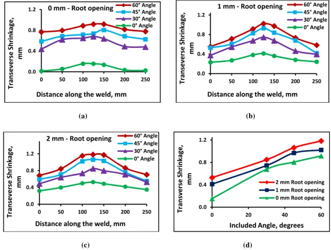
Distribution of transverse shrinkage in the single V-groove butt joints for different included angles along the length of the specimen are plotted for 0 mm, 1 mm and 2 mm root opening as shown in the figure 1 (a), (b) and (c) respectively. It is found that, the transverse shrinkage is maximum at the centre of the weld and minimum at the ends. The variation of transverse shrinkage along the length of the weld may be due to tack welds at the ends and higher rate of cooling of the weld metal. It can also be seen that, as the included angle increases, there is an increase in the transverse shrinkage.
(a) (b)
(c) (d)
Figure 1: Distribution of transverse shrinkage along the weld length for different included angle for (a) 0 mm root opening, (b) 1 mm root opening, (c) 2 mm root opening and (d) Variation of maximum transverse shrinkage with included angle for different root openings, in case
0.0 0.4 0.8 1.2
0 50 100 150 200 250
Transeverse
Shrinkage,
mm
Distance along the weld, mm
0 mm ‐Root opening 60° Angle
45° Angle 30° Angle 0° Angle
0.0 0.4 0.8 1.2
0 50 100 150 200 250
Transeverse
Shrinkage,
mm
Distance along the weld, mm
1 mm ‐Root opening 60° Angle
45° Angle 30° Angle 0° Angle
0.0 0.4 0.8 1.2
0 50 100 150 200 250
Transeverse
Shrinkage,
mm
Distance along the weld, mm
2 mm ‐Root opening 60° Angle
45° Angle 30° Angle 0° Angle
0.0 0.4 0.8 1.2
0 20 40 60
Transverse
Shrinkage,
mm
Included Angle, degrees
Variation of maximum transverse shrinkage of a specimen verses included angle for different root opening in case of V-groove weld joints are plotted as shown in the figure 1(d). There is an increase in the transverse shrinkage with increase in the included angle. The increase in the shrinkage may be due to the decrease in the exposed area of deposited weld metal to the surrounding. In other words, decrease in the exposed area decreases the rate cooling of weld metal, which intern increases shrinkage.
5.2. Effect of included angle on longitudinal shrinkage in single V-groove butt welded plates
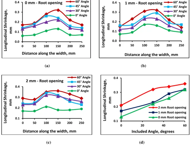
Distribution of longitudinal shrinkage in the single V-groove butt joints for different included angles along the width of the specimen are plotted for 0 mm, 1 mm and 2 mm root opening as shown in the figure 2(a), (b) and (c) respectively. It is found that, the longitudinal shrinkage is quite higher at the weld bead when compared to the values at the away from the weld bead. This may be due to the weld bead at the centre that will contract more compared to the ends of the plate leads to higher shrinkage near the weld region.
(a) (b)
(c) (d)
Figure 2: Distribution of longitudinal shrinkage along the width of the specimen for different included angle for (a) 0 mm root opening, (b) 1 mm root opening, (c) 2 mm root opening and (d) Variation of maximum longitudinal shrinkage with included angle for different root
openings, in case of single V-Groove weld joints.
The variation of maximum longitudinal shrinkage of a specimen with included angle for different root openings in case of V-groove weld joints are plotted as shown in the figure 2(d). There is a little increase in the longitudinal shrinkage with increase in the included angle. This can be due to higher rate of cooling of the weld metal in the weld region for lower included angle due to more expose of the weld metal to the surrounding. The increase in longitudinal shrinkage is less than that of transverse shrinkage. This may be due to the fact that, the restraint forces from the base plate in longitudinal directions are more than that in the transverse directions
0.0 0.1 0.2 0.3 0.4
0 50 100 150 200 250
Longitudin
a
l
Shrinkage,
mm
Distance along the width, mm
0 mm ‐Root opening 60° Angle
45° Angle 30° Angle 0° Angle
0.0 0.1 0.2 0.3 0.4
0 50 100 150 200 250
Longitudin
a
l
Shrinkage,
mm
Distance along the width, mm
1 mm ‐Root opening 60° Angle
45° Angle 30° Angle 0° Angle
0.1 0.2 0.3 0.4
0 50 100 150 200 250
Longitudin
a
l
Shrinkage,
mm
Distance along the width, mm
2 mm ‐Root opening
60° Angle 45° Angle 30° Angle 0° Angle
0.1 0.2 0.3 0.4
0 20 40 60
Longitudin
a
l
Shrinkage,
mm
Included Angle, degrees
5.3. Effect of included angle on transverse shrinkage in double V-groove butt welded plates
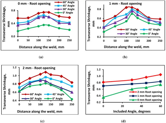
In double V-groove butt joints, distribution of transverse shrinkage for different included angles and for 0 mm, 1 mm and 2 mm root opening are shown in the figure 3(a), (b) and (c) respectively. The transverse shrinkage is maximum at the centre of the weld line and minimum at the ends. This distribution of transverse shrinkage along the length of the weld may be due to the tack welds and the different rates of cooling. The faster rates of cooling at the ends of weld line may prevent the contraction of the weld metal which may leads to the lower values at the ends.
(a) (b)
(c) (d)
Figure 3: Distribution of transverse shrinkage along the weld length for different included angle for (a) 0 mm root opening, (b) 1 mm root opening, (c) 2 mm root opening and (d) Variation of maximum transverse shrinkage with included angle for different root openings, in case
of double V-Groove weld joints.
Variation of maximum transverse shrinkage of a specimen with included angle for different root openings in case of double V-groove butt welded joints are plotted as shown in the figure 3(d). It is found that, the transverse shrinkage increases as increase in the included angle. This may be due to the decrease in the rate of cooling.
5.4. Effect of included angle on longitudinal shrinkage in double V-groove butt welded plates
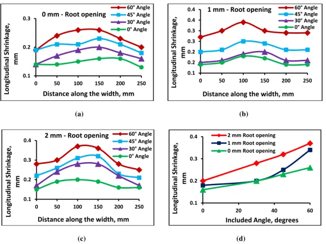
In the double V-groove butt joints, distribution of longitudinal shrinkage for different included angles along the width of the specimen are plotted for 0 mm, 1 mm and 2 mm root opening is shown in the figure 4(a), (b) and (c) respectively. It is found that, the longitudinal shrinkage is quite higher at the centre of the weld when compared to the values at the ends as in case of transverse shrinkage. This distribution of longitudinal shrinkage along the length of the weld may be due to the weld bead at the centre that will contract more compared to the ends which causes for non-uniform temperature distribution.
0.0 0.4 0.8
0 50 100 150 200 250
Transeverse
Shrinkage,
mm
Distance along the weld, mm
0 mm ‐Root opening 60° Angle
45° Angle 30° Angle 0° Angle
0.2 0.4 0.6 0.8
0 50 100 150 200 250
Transeverse
Shrinkage,
mm
Distance along the weld, mm
1 mm ‐Root opening
60° Angle 45° Angle 30° Angle 0° Angle
0.4 0.6 0.8 1.0 1.2
0 50 100 150 200 250
Transeverse
Shrinkage,
mm
Distance along the weld, mm
2 mm ‐Root opening
60° Angle 45° Angle 30° Angle 0° Angle
0.2 0.4 0.6 0.8 1.0 1.2
0 20 40 60
Transverse
Shrinkage,
mm
Included Angle, degrees
(a) (b)
(c) (d)
Figure 4: Distribution of longitudinal shrinkage along the width of the specimen for different included angle for (a) 0 mm root opening, (b) 1 mm root opening, (c) 2 mm root opening and (d) Variation of maximum longitudinal shrinkage with included angle for different root
openings, in case of double V-Groove weld joints.
Variation of maximum longitudinal shrinkage of a specimen with included angle for different root openings in case of double V-Groove weld joints are plotted as shown in the figure 4(d). There is a little increase in the longitudinal shrinkage with increase in the included angle. This can be due to non-uniform rate of cooling of the weld metal in the weld region due to the non-uniform expose of the weld metal to the surrounding for different included angles. The increase in longitudinal shrinkage is less than that of transverse shrinkage. This happens due to the fact that, the restraint forces from the base plate in longitudinal directions are more than that in transverse directions. The variation in transverse shrinkage is more than that of longitudinal shrinkage. This could be due to the fact that, the restraint forces from the base plate in longitudinal directions are more than that in transverse directions.
6. Conclusions
The predictions of the degree of shrinkage in ship panels, structures, airplanes, buildings, pressure vessels etc., due to welding are of great importance from the point of view of dimensional control. The results obtained by experimental investigation will be of great useful to the designers to account for the shrinkages taking place during fabrication of various plates. The main conclusions are drawn within the scope of the present investigation are as follows:
(1) The transverse shrinkage is maximum at the centre and minimum at the ends of the weld line and the
variation is significant.
(2) Similar to the transverse shrinkage the longitudinal shrinkage is maximum at the weld line and decreased on
either side away from the weld line but the variation is small.
(3) The both transverse and longitudinal shrinkage are increased with increase in the included angle in case of
single and double V-groove butt joints.
(4) The variation of transverse shrinkage is found to be significant but the variation of longitudinal shrinkage is
found to be small both in single and double V-groove butt joints. 0.1
0.2 0.3
0 50 100 150 200 250
Longitudin
a
l
Shrinkage,
mm
Distance along the width, mm
0 mm ‐Root opening
60° Angle 45° Angle 30° Angle 0° Angle
0.1 0.2 0.2 0.3 0.3 0.4 0.4
0 50 100 150 200 250
Longitudin
a
l
Shrinkage,
mm
Distance along the width, mm
1 mm ‐Root opening 60° Angle
45° Angle 30° Angle 0° Angle
0.1 0.2 0.3 0.4
0 50 100 150 200 250
Longitudin
a
l
Shrinkage,
mm
Distance along the width, mm
2 mm ‐Root opening 60° Angle
45° Angle 30° Angle 0° Angle
0.1 0.2 0.3 0.4
0 20 40 60
Longitudin
a
l
Shrinkage,
mm
Included Angle, degrees
References
[1] Masubuchi, K. Control of distortion and shrinkage in welding. WRC Bulletin 149, April 1970, pp.1-30. [2] Nadkarni, S, V. Modern Arc Welding Technology. Oxford and IBH Publishing Co. Pvt. Ltd. 1992.
[3] Mochizuki, M., Mikami, Y., Toyoda, M. and Yamasaki, H. Elastic predicting of weld distortion of large structures using numerical simulation results by thermal-elastic-plastic analysis of small components. Welding in the world. Vol-51, No.11/12: 2007, pp 42-46. [4] Tsai, C. L. Using Computers for the Design of Welded Joints. Welding Journal: 1991, pp 47-56.
[5] Mandal, N. R. and Sundar, C. V. N. Analysis of Welding Shrinkage. Welding Journal 76(6): 1997, pp 233s-238s.
[6] Pavlovsky, V. I., Masubuchi, K. Research in the U. S. S. R. on residual stresses and distortion in welded structures. WRC Bulletin 388, pp. 1-62.
[7] Masubuchi, K. Residual Stresses and Distortion. Welding Handbook, pp. 218-264.