Effect of Residual Stresses of GTA Welding for Dissimilar Materials
Harinadh Vemanaboinaa* , Gundabattini Edisona, Suresh Akellab, Ramesh Kumar Budduc
Received: December 02, 2017; Revised: March 18, 2018; Accepted: May 16, 2018
The purpose of the present work is to understand the evolution of residual stresses in weldments. The study made to weld the multipass dissimilar of Nickel-based superalloy Inconel 625 and stainless steel 316L using Continuous Current Gas Tungsten Arc Welding (CCGTAW) and Pulsed Current Gas
Tungsten Arc Welding (PCGTAW) process employing ERNiCrMo-3 and ERNiCr-3 fillers. The L4 orthogonal array was used in the present experimentation process. Analysis of Variance (ANOVA) is applied for the optimization and to identify the critical parameters. In welding process, the size of the lattice size will be stressed due to welding parameters; the lattice dimension is measured
by non-destructive technique X-Ray diffraction to investigate residual stress in the weldment in
the lateral surface of the plate. X-Ray Radiography test has evaluated the quality of welds. The
results show that root gap is a critical parameter and filler wire and weld processes are not critical.
Keywords: GTAW, Dissimilar Materials, Multipass Welding, Residual Stress, XRD, ANOVA.
*e-mail: [email protected]
1. Introduction
Welding of similar or dissimilar materials having individual thermal properties (density, linear expansion,
specific heat, conductivity) and mechanical properties (yield
strength, Poisson's ratio) lead to changes in residual stress and distortion and metallurgical properties. This causes inhomogeneous plastic deformation leading to defects like distortion and residual stresses in the welded parts. Stresses within a material are thoroughly isolated into two essential orders (a) within and (b) external surfaces. External stress is related to exterior loads coupled during the manufacturing or machining and cyclic operations process of material; internal stress is naturally present inside the material even though no external forces are acting on it.
Dissimilar materials joining will minimize the weight and cost of the component, where demand for such materials are necessary for various industrial application such as nuclear, automobile, aerospace, power plants and chemical plants. The multi-pass welding process is used for welding of thick metals. For each of the passes (heat),
equal intervals of time are taken to fill the material at
groove designed. The material undergoes transient heating and cooling cycles during these processes. The size of the lattice size of metal is stressed even after the metal cools down to room temperature. The researchers had developed multi-purpose 3D models for the welding process to study the temperatures, distortions, and residual stresses. Simulation of butt joints for weldments using the single pass, multi-pass welding with element birth and death techniques for laser beam and arc welding process using ANSYS packages 1,2,3,4.The initial, temperature dependent
material properties, convection, and radiation boundary conditions are also adopted for welding processes. Heat is concentrated at the welding zone during the welding process; the weld portion will undergo thermal cycles
for thick workpieces while filling of material in grooves,
during the addition of the material non-uniform heating and cooling occurs during each pass for thick materials, this leads to the generation of residual stresses in the weld structures. Murugan5 has studied the multipass welding of various thick plates, the temperature and residual stresses measured either side of the weldment pass by pass, with
thermocouples and X-Ray diffraction. Residual stress
developed during the machining or manufacturing process,
these were measured using the X-ray diffraction6 is a nondestructive measurement method using this equipment we can know the atomic lattice spacing in the measured component. Lei XU7 had discussed weld with K-PAW process for making T-joint with thin plate used for aerospace application and study about the measurement of residual
stress using synchrotron X-ray diffraction and FEA. The
residual stress is measured using ultrasonic techniques; welding was carried out with TIG and A-TIG processes for thick plate welds8. The residual stress measurement is done through XRD, before and after post weld treatment for butt tube joints9. Laser beam welding process has narrow fusion zone and narrower residual stress distribution in weld structures, the butt joints are made for thick plates pre and post weldment vibratory stress relief (VSR) treatment for weldment at low frequency, where this technique was used for reducing the residual stress to 100 MPa10. Surface residual stresses were measured by ED-Hole
aSchool of Mechanical Engineering - SMEC, VIT University, Vellore, Tamilnadu, India
bSreyas Institute of Engineering & Technology, Hyderabad, India
drilling strain gauge method, and it was also evaluated in
thickness using X-ray diffraction, the study also includes
the metallurgical characterization11. The detailed study of dissimilar butt welding joints are made for Inconel 625 and AISI 316L, with both continuous and pulsed current
GTAW process, and two filler wires were included for
weldability, metallurgical and mechanical properties of joints12. The investigation of residual stress of dissimilar butt pipe welding was studied by the nondestructive
capability of LCR ultrasonic method, the finite element
model, hole-drilling and ultrasonic stress measurements methods are employed on two dissimilar welded pipes13.
It is evident from the literature; no studies were reported on residual stress measurement for multipass dissimilar weldments of SS316L to Inconel 625. In the present work, the multipass dissimilar joints are achieved with both continuous current GTAW and pulsed current GTAW processes by
using the ERNiCr-3 and ERNiCrMo-3 filler wires. The
L4 orthogonal array is employed to identify the critical parameters for generation of residual stresses. The residual stress is measured in the transverse direction to weld. The measurement is carried out at fusion zone in the weldment
by using the X-Ray diffraction non-destructive technique.
2. Experimental Work
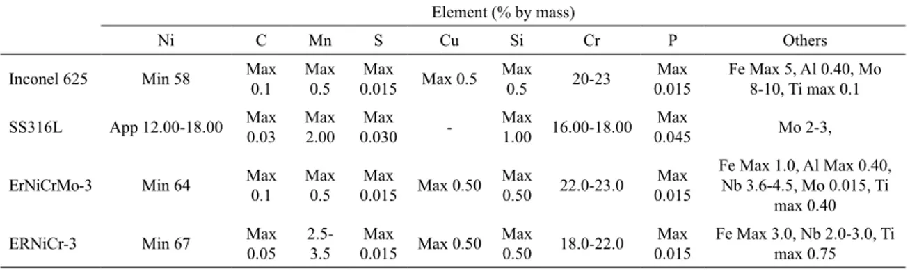
The chemical composition of the base metals Inconel
625 to SS316L and filler metals ERNiCrMo-3 and ERNiCr-3 is shown in Table 1. ERNiCrMo-3 and ERNiCr-3 fillers are
utilized to weld dissimilar metal combinations, for example, steel, stainless steel, Inconel, and Inconel alloys for GTAW, GMAW, and ASAW processes. The dimensions of the samples employed for the present study of 110 mm x 60 mm x 5 mm. The standard single V-groove design was employed for butt joints, with an included angle of 60º is used for dissimilar joints. The investigation is involved in both CCGTA welding and PCGTA welding processes. The L4 orthogonal array was chosen for the present experimentation as shown in Table 2. The processes parameters employed in multi-pass GTAW process (CCGTAW and PCGTAW) of dissimilar welding (Inconel 625 to SS316L) are represented in Table 3.
In this study, three passes are employed for each weld
sample for adding of different filler materials at root, filler
and cap pass at groove designed for formation of the joint. The current was used for CCGTAW process were 140 Amps and for PCGTAW was 160 Amps with background current
was 80 Amps, welding voltage 13-15 Volts and flow rate 10
Table 1. Chemical properties of the materials
Element (% by mass)
Ni C Mn S Cu Si Cr P Others
Inconel 625 Min 58 Max 0.1
Max 0.5
Max
0.015 Max 0.5 Max
0.5 20-23
Max 0.015
Fe Max 5, Al 0.40, Mo 8-10, Ti max 0.1
SS316L App 12.00-18.00 Max 0.03 Max 2.00 Max 0.030 -Max 1.00 16.00-18.00 Max
0.045 Mo 2-3,
ErNiCrMo-3 Min 64 Max
0.1 Max
0.5 Max
0.015 Max 0.50 Max
0.50 22.0-23.0 Max 0.015
Fe Max 1.0, Al Max 0.40, Nb 3.6-4.5, Mo 0.015, Ti
max 0.40
ERNiCr-3 Min 67 Max
0.05
2.5-3.5 Max
0.015 Max 0.50 Max
0.50 18.0-22.0 Max 0.015
Fe Max 3.0, Nb 2.0-3.0, Ti max 0.75
Table 2. L4 Orthogonal array
Trails 1 2 3
1 1 1 1
2 1 2 2
3 2 1 2
4 2 2 1
Table 3. Process parameters and its levels
S.No Process Root gap Filler Pulsed Current
Base current or welding current
Voltage Avg Welding speed Heat input
P1 P2 P3
mm Amps Amps Volts mm/sec kJ/mm
1 CC 1.8 ERNiCr-3 - 140 140 140 13 95.9 0.86
2 CC 2.0 ERNiCrMo-3 - 140 140 140 13 152.39 1.25
3 PC 1.8 ERNiCrMo-3 80 160 160 160 15 60.92 0.74
L/min was maintained constant for both the processes and two
different filler wires are used for each process. The sequence
of weld passes employed for the experimentation is shown in Figure 1. The interpass time and interpass temperature are maintained between the passes 14,15. After each pass, the interpass temperature is maintained below 150ºC to avoid cracking of the weld sample16. The welded samples are free
from weld defects, is verified from the X-Ray radiography
NDT inspection samples are shown in Figure 2.
the goniometer with head, with VantecTM area detector and appropriate video plus laser tracking. Measured, at the centre of the tube cross-section using standard d-sin2Ψ 17,18.Residual stress is measured at Fusion zone of weld material; of the lateral surface on weld samples, for calculation19 of the residual stress, the following Equation-2 is used.
(2)
Figure 1. Schematic diagram of multipass process
Figure 2. GTA Welded samples
3. Residual Stress
Residual stresses caused by thermal stresses even after external forces are removed in the material. The axial residual stress is measured in the transverse direction (weld direction)
on the surface of the weldment by using the X-ray diffraction
with Bragg's angle is given in Equation-1.
(1)
where n= the order of reflection beam,
d= interplaner lattice spacing and
θ =Bragg angle
The material is in tension, the d-spacing increases and when the material is in compression, the d-spacing decreases are varied due to welding parameters and its cooling rate. The residual stresses are uneven in distribution either sides of the weldments due to its thermal properties (thermal expansion). The residual stress measurement was carried
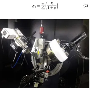
out using the microfocus X-ray diffraction: a Bruker
D8-DiscoverTM system is shown in Figure 3, and Figure 4 shows
sin
nm=2d i
d m
v E
1
0 v =
+
z
S
X
Figure 3. Bruker X-Ray Diffraction
Figure 4. Schematic of goniometer head with detector
The X-Ray Diffraction waves are picked up by detectors
positioned detector mounted on an arc-shaped goniometer, with
a diffraction angle (2θ), it ranges from of 20º-90º. In Figure 5
the peak positions were observed for all samples. Obtaining a
diffraction peak of suitable intensity is important. The peaks
must be free of interference from neighbouring peaks. So that
the diffraction angle 2θ can be measured experimentally and the d-spacing is then calculated using Bragg's law. The 2θ value is
74.6 and shown in Figure 5. The strategy of stress estimations
includes recording the profile of diffraction at various angle points ѱ with an interplanar spacing of "d". Using the resultant
surface residual stresses in the given direction is estimated 20,21,22,23. The other two parameters are width and intensity of
diffraction measuring of peaks in work surface can give the better microstructure data identified in the explored surface. Related grain size and deformation represent the diffraction peak at different ѱ inclination angles.
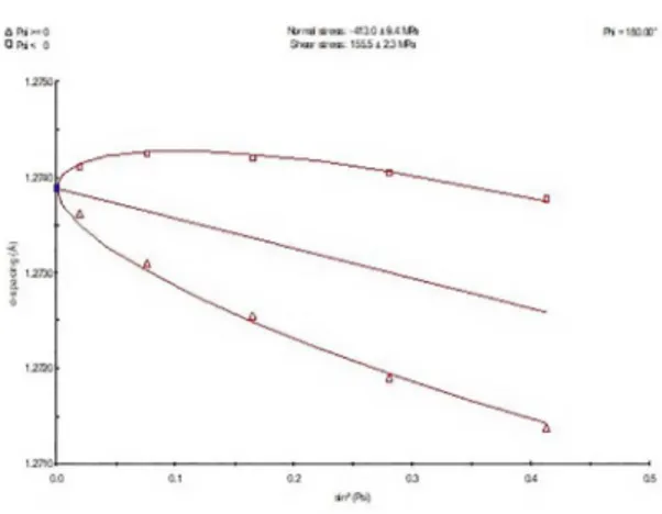
Figure 6 shows the regular d vs sin2 Ψ for the weldment at fusion zone and for calculating the residual stress Equation-2 were used. The data of d0is also taken from Figure 6, slope 'm' is measured by drawing lines between d spacing and sin2 Ψ, E and v are Young's modulus and Poisson's ratio of the materials. The individual measured value of d vs sin2 Ψ is used for slope 'm' and this is used for calculating the residual stress using Equation-2 for all combinations. The residual stresses of various combinations are shown in Table 4.
4. Results and Discussions
The aspect ratio of the weldment various with the process parameters used for both CC and PC GTAW process. The welded bead geometry was measured at the lateral surface of the plates; measurement was taken place in horizontal and vertical directions of in the thickness of the weldments are shown in Table 5. The higher depth of penetration is preferable for the weldments and lower the bead width. The larger the bead width is observed in lower root opening and better depth of penetration for all the weldments.
In the design of experiments, the objective is to identify the critical parameters which will help in obtaining the desired outputs. In the welding process, we will like the output of temperature, residual stress and distortion to have minimum mean and lower the better. To obtain these outputs, we have identified parameters: voltage, current, root gap and flow rate as the parameters. These might be critical parameters or may not be, No-Way Anova estimate indicates whether these parameters critical are not. In No-Way they are two parameters mean, and variation about the mean, the sum of squares of errors gives us an indication of this
Figure 5. 2theta measurement θ= 74.6
Figure 6. D spacing vs sin2 Ψ
Table 4. Bead geometry characteristics of the GTA welding processes weldments
Sample Id Photo of sample
Trail-1
Horizontal line-1: 9.84 Horizontal line -2: 4.29 Horizontal line-3: 3.23
Vertical line :5.5 Bead height : 0.88
Trail-2
Horizontal line-1: 8.99 Horizontal line -2: 6.01 Horizontal line-3: 7.59
Vertical line: 4.97 Bead height : 1.18
Trail-3
Horizontal line-1: 11.16 Horizontal line -2: 6.69 Horizontal line-3: 6.38
Vertical line: 4.97 Bead height : 1.08
Trail-4
Horizontal line-1: 9.15 Horizontal line -2: 7.12 Horizontal line-3: 8.49
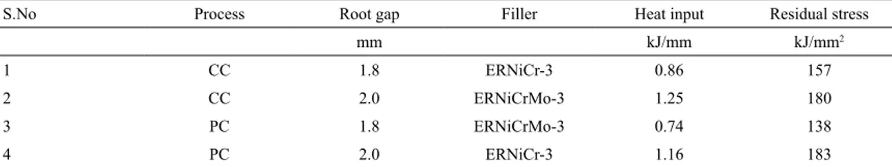
Table 5. Residual stress of the weldments
S.No Process Root gap Filler Heat input Residual stress
mm kJ/mm kJ/mm2
1 CC 1.8 ERNiCr-3 0.86 157
2 CC 2.0 ERNiCrMo-3 1.25 180
3 PC 1.8 ERNiCrMo-3 0.74 138
4 PC 2.0 ERNiCr-3 1.16 183
Figure 7. Variation of mean and data about zero
Table 6. Calculation of Sum of Squares
SST=ƩYi2 109582
Sum, S=ƩYi 658
Avg. T = Sum/Expts. =S/N 164.5
SSm=S2/N=N*(T*T) 108241
SSe=SST-SSm, Error sum of
Squares 1341
variation. If the variation is less the selected parameters are not effective and may not effective if the variation is more, we might have included critical parameters in our experimentation. This objective of doing No-way Anova first before doing Anova.
This is the analysis of the data without any parameter being assigned, that is the reason for the word No Way. In This analysis, the response is residual stress which has a requirement of Lower the better. In No Way ANOVA, a variation of all data about reference point zero is evaluated. In No Way, two variants are seen
i Variation of mean about zero
ii Variation of the individual values about Average (called experimental errors)
Total Number of Experiments is N=4. The data of mean and each residual value for four experiments is shown in Figure 7, has response residual stress varying about zero also the mean varying about zero. The values of Sum of Squares of mean, SSm, Total Sum of Squares, SST are shown in Table 6. From these two values, Sum of Squares of Error, SSe are calculated as SSe=SST-SSm. Sum of squares gives the variance.
Akella24,25 has given a method comparison of variance
hypothesis test of significance called F-test. In No-Way
ANOVA, the test of hypothesis is between the variance of mean and of error. Sum of square value is same as variance, the ratio of SSm, SSe is compared with the Fα,ν1,ν2, where α
is the risk and (1-α) is the significance, ν1 is the degrees of freedom (DOF) of the numerator, which is of mean and ν2
is the dof of the denominator which is of error. If F0.01,ν1,ν2 is greater than Fcalculated then the null hypothesis is rejected, and
alternate hypothesis is accepted to a significance of (1-α).
From Table 7. Fcalculated is greater than F0.05,1,3 and is also greater than F0.01,1,3 with 99% confidence we can say variance of mean and variance of error belong to
different estimates. That is a variation of mean, from zero level, is a significant parameter. Experiments are going to give significant results up to 99% confidence. The
No-way ANOVA, the design of experiments, selection
of parameters and levels are effective in identifying the
critical parameters as shown by the variation of 138 to 183 MPa about the mean value.
In Table 8., the ANOVA summary for the parameters
on effect on residual stress is calibrated. As Fcaluculated is greater than F.01,1,5 filler wire selection is important to
control residual stresses with 95% confidence we can
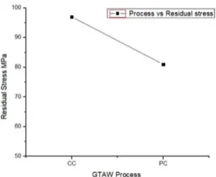
say factor B, Root Gap is important. Level 1 is 1.8 mm, and the residual stresses are 78 MPa lower than level 2 of root gap 2.0 the residual stress is 100 MPa as shown in Figure 8. The welding process pulsed current process
is not significant with level 2 shows better residual stress
than continuous current as shown in Figure 9. The Level
1 is filler wire with Molybdenum (Mo), this is giving residual stress of 138 MPa, and Level 2 is filler wire
without Molybdenum (No Mo), this is giving residual stress of 183 MPa. As the required response is lower the better, Filler wire with Mo, ERNiCrMo-3 is giving low
Table 7. No Way ANNOVA
Source SS DOF Variance F-Table F.1,1,3 F..05,1,3 F.01,1,3
Mean, SSm 108241 1 108241 242.1498881 5.54 10.1 34.1
Error, SSe 1341 3 447
Total, SST 109582 4
Table 8. ANOVA Summery
Source SS DOF, ν Variance, V F-Table F.1,1,5 F..05,1,5 F.01,1,5 P, %
Contribution
A, Process 64 1 64 0.52892562 4.06 6.61 16.8 4.377565
B, Root Gap 1156 1 1156 9.553719008 ++ 79.06977
C, Filler
wire 121 1 121 1 8.276334
Error 121 1 121 8.276334
SST 1462 4 100
Figure 8. Effect of root gap on residual stress
Figure 9. Effect of process on residual stress
Figure 10. Effect of Filler wire on residual stress
5. Conclusions
The dissimilar materials; SS316L and IN625, were welded with constant current and pulsed current GTAW process with
different filler wires and root gaps. The weldments are free from defects, and the same is verified using Radiography. The
No-Way ANOVA by Taguchi was calculated and has shown that the experiments have a critical parameter with 99%
confidence. Residual stresses were found using X-ray diffraction
(XRD), and only root gap parameter was found critical with
95% confidence; both filler wire and welding process had no significant effect on residual stress. For least residual stress the
levels of welding parameters recommended are 1.8 mm Root gap, the pulsed current process of welding and ERNiCrMo-3
filler wire, the expected residual stress is138 MPa which gives
a factor of safety of 1.4 for SS316L material and 1.5 for IN625.
This procedure can be effectively utilized to reduce residual
6. Acknowledgement
The authors also acknowledge support from the National Facility of Texture and OIM - A DST-IRPHA facility at IIT Bombay.
References
1. Capriccioli A, Frosi P. Multipurpose ANSYS FE procedure for welding processes simulation. Fusion Engineering and Design. 2009;84(2-6):546-553.
2. Vemanaboina H, Akella S, Buddu RK. Welding Process Simulation Model for Temperature and Residual Stress Analysis. Procedia Materials Science. 2014;6:1539-1546.
3. Akella S, Harinadh V, Krishna Y, Buddu RK. A Welding Simulation of Dissimilar Materials SS304 and Copper. Procedia Materials Science. 2014;5:2440-2449.
4. Akella S, Vemanaboina H, Buddu RK. Effect of Heat Flow Condition in Analysis of Electron Beam Welding. Sreyas International Journal of Scientists and Technocrats. 2016;1(1):1-9.
5. Murugan S, Rai SK, Kumar P, Jayakumar T, Raj B, Bose MSC. Temperature distribution and residual stresses due to multipass welding in type 304 stainless steel and low carbon steel weld pads. International Journal of Pressure Vessels and Piping. 2001;78(4):307-317.
6. Umapathi A, Swaroop S. Residual stress distribution in a laser peened Ti-2.5Cu alloy. Surface and Coatings Technology. 2016;307(Pt A):38-46.
7. Xu L, Zhang SY, Sun W, McCartney DG, Hyde TH, James J, et al. Residual stress distribution in a Ti-6Al-4V T-joint weld measured using synchrotron X-ray diffraction. The Journal of Strain Analysis for Engineering Design. 2015;50(7):445-454.
8. Vasantharaja P, Vasudevan M, Palanichamy P. Effect of welding processes on the residual stress and distortion in type 316LN stainless steel weld joints. Journal of Manufacturing Processes. 2015;19:187-193.
9. Rai S, Jayakumar T, Rao CB, Bhattacharya DK, Raj B. Residual stress measurement in ferritic steel tube welds using X-ray diffraction. Science and Technology of Welding and Joining. 1998;3(4):204-207.
10. Mohanty S, Arivarasu M, Arivazhagan N, Phani Prabhakar KV. The residual stress distribution of CO2 laser beam welded AISI 316 austenitic stainless steel and the effect of vibratory stress relief. Materials Science and Engineering: A. 2017;703:227-235.
11. Azizpour MJ, Nourouzi S. Evaluation of surface residual stresses in HVOF sprayed WC-12Co coatings by XRD and ED-hole drilling. Journal of Mechanical Science and Technology. 2013;27(9):2709-2713.
12. Kumar KG, Ramkumar KD, Arivazhagan N. Characterization of metallurgical and mechanical properties on the multi-pass welding of Inconel 625 and AISI 316L. Journal of Mechanical Science and Technology. 2015;29(3):1039-1047.
13. Javadi Y, Afzali O, Raeisi MH, Najafabadi MA. Nondestructive Evaluation of Welding Residual Stresses in Dissimilar Welded Pipes. Journal of Nondestructive Evaluation. 2013;32(2):177-187.
14. Buddu RK, Chauhan N, Raole PM. Mechanical properties and microstructural investigations of TIG welded 40 mm and 60 mm thick SS 316L samples for fusion reactor vacuum vessel applications.
Fusion Engineering and Design. 2014;89(12):3149-3158.
15. Buddu RK, Chauhan NL, Raole PM. Investigations of Microstructure and Mechanical Properties of 60-mm-Thick Type 316L Stainless Steel Welded Plates by Multipass Tungsten Inert Gas Welding and Electron Beam Welding for Fusion Reactor Applications.
Fusion Science and Technology. 2014;65(2):248-254.
16. Chandel R. Effect of Welding Parameters and Groove Angle on
the Soundness of Root Beads Deposited by the Saw Process. Ottawa: Energy, Mines and Resources Canada, CANMET; 1985.
17. Kumar G, Balo S, Dhoble A, Singh J, Singh R, Srivastava D, et al. Through-Thickness Deformation Gradient in a Part-Pilgered Zirconium Tube: Experimental Measurements and Numerical Validation. Metallurgical and Materials Transactions A. 2017;48(6):2844-2857.
18. Kumar G, Kanjarla AK, Lodh A, Singh J, Singh R, Srivastava D, et al. Burst Ductility of Zirconium Clads: The Defining Role of Residual Stress. Metallurgical and Materials Transactions A. 2016;47(8):3882-3896.
19. Anderoglu O. Residual Stress Measurement Using X-ray Diffraction. [Thesis]. College Station: Texas A & M University; 2005.
20. Cullity BD. Elements of X-ray Diffraction. 2nd ed. Boston:
Addison-Wesley; 1978.
21. Noyan IC, Cohen JB. Residual Stress - Measurement by Diffraction and Interpretation. New York: Springer; 1987. 22. Ganesh P, Nagpure DC, Kaul R, Gupta RK, Kukreja LM.
Non-destructive Micro-structural Characterization of Metallic Specimens with a Portable X-ray Diffraction based Residual Stress Analyzer. Studies in Engineering and Technology. 2015;2(1):22-32.
23. Kim CS, Hong KS, Kim MK. Nonlinear robust control of a hydraulic elevator: experiment-based modeling and two-stage Lyapunov redesign. Control Engineering Practice. 2005;13(6):789-803.
24. Akella S, Kumar BR, Krishnaiah Y. Optimisation of welding process parameters for distortion control with Taguchi approach.
International Journal of Precision Technology. 2013;3(2):206-219.
25. Ross PJ. Taguchi Techniques for Quality Engineering. 2nd ed.