Intermetallics 116 (2020) 106656
Available online 15 November 2019
0966-9795/© 2019 Elsevier Ltd. All rights reserved.
Controlling intermetallic compounds formation during laser welding of
NiTi to 316L stainless steel
A. Shamsolhodaei
a,*, J.P. Oliveira
b, N. Schell
c, E. Maawad
c, B. Panton
d, Y.N. Zhou
aaCentre of Advanced Materials Joining, Department of Mechanical & Mechatronics Engineering, University of Waterloo, 200 University Avenue West, Waterloo, Ontario, N2L 3G1, Canada
bUNIDEMI, Departamento de Engenharia Mec^anica e Industrial, Faculdade de Ci^encias e Tecnologia, Universidade NOVA de Lisboa, Caparica, Portugal cInstitute of Materials Research, Helmholtz-Zentrum Geesthacht, Max-Planck-Str. 1, D-21502, Geesthacht, Germany
dWelding Engineering, Department of Materials Science and Engineering, The Ohio State University, 1248 Arthur E. Adams Drive, Columbus, OH, 43221, USA
A R T I C L E I N F O Keywords:
Laser welding Intermetallic compounds NiTi shape memory alloys Stainless steel
Dissimilar joining Synchrotron X-ray diffraction
A B S T R A C T
Dissimilar laser welding of NiTi to stainless steel is of great importance in designing medical devices but the formation of hard and brittle intermetallic compound results in low strength joints. Normally, different in-terlayers are applied as physical and chemical barriers to control the microstructure and to improve the me-chanical properties. However, this procedure is a cost and time consuming process and may cause the formation of other types of intermetallics depending on the interlayer used. In the present work, laser offsetting welding (LOW) was introduced without inserting any interlayer by shifting the laser beam 100 μm into the stainless steel
from the NiTi/316L stainless steel interface. This led to a softer weld zone (~570 H V), due to the formation of less brittle intermetallics compounds (Fe2Ti, Cr2Ti and Ni3Ti) compared to that (~970 H V) when the laser beam
was placed at the NiTi/316L stainless steel interface. For comparison purposes, an Ni interlayer was also used to control the chemical composition of the fusion zone. In terms of mechanical properties, both the laser offset welding and the use of an Ni interlayer, were seen to improve the tensile strength of the dissimilar joints (above 400 MPa) compared to the centerline welding condition (around 200 MPa). Hence, LOW was confirmed to be an effective method to laser weld the NiTi/Stainless Steels.
1. Introduction
Shape memory effect, superelasticity and biocompatibility of NiTi made this shape memory alloy one of the greatest candidates for use in a wide range of applications including biomedical engineering [1,2]. These functional materials are used as stents, orthodontic archwires or catheter guide-wires [3]. There are a few publications that investigate the similar laser welding of these smart materials [4,5], however, in order to expand the applications and achieve complex geometries in a multi-material system, dissimilar joining of NiTi to other biomaterials such as stainless steels is in high demand. Consequently, the overall system could benefit from each component’s properties [6].
Dissimilar joining of NiTi and stainless steel has attracted significant attention, owing to a number of limitations in medical devices produced by only either NiTi or stainless steel [7,8]. For instance, the high elastic modulus of stainless steel is a reason for the failure of satisfactory teeth straightening performance of stainless steel orthodontic archwires. On
the other hand, the guidewires fabricated by only NiTi suffers from too much flexibility. Therefore, taking advantage of the hybrid properties of stainless steel and NiTi could be an opportunity for optimizing the biomedical devices which could be achieved by dissimilar joining of these materials.
To date, several studies have investigated laser welding of NiTi and stainless steel which lead to undesirable results, mainly due to the for-mation of intermetallic compounds (IMCs) in the fusion zone such as Fe2Ti and Ti2Ni [9–11]. Based on NiTi/stainless steel dissimilar joints
studies and also taking the ternary phase diagram of Ni–Ti–Fe into consideration [12], Fe2Ti/γ-(Fe,Ni) eutectic adjacent to the stainless
steel/weld zone interface, Fe2Ti/(Fe, Ni)Ti/Ni3Ti eutectic inside the
weld zone and Ni3Ti/(Fe, Ni) Ti adjacent to NiTi/weld zone interface
can be formed. These extensive and complex networks of different hard and brittle IMCs are responsible for low strength nature and extreme brittleness of NiTi/stainless steel joints [13,14].
Therefore, several researchers used different interlayers in order to
* Corresponding author.
E-mail address: ashamsol@uwaterloo.ca (A. Shamsolhodaei).
Contents lists available at ScienceDirect
Intermetallics
journal homepage: http://www.elsevier.com/locate/intermet
https://doi.org/10.1016/j.intermet.2019.106656
prevent the formation of these harmful IMCs and improve the joint’s mechanical properties. In this regard, several elements such as Ni [15,
16], Co [17], Ta [18–20] and Cu [21] were adopted to hinder the for-mation of the aforementioned IMCs and modify the microstructure in different areas of the weld zone. In addition, it has been reported that inserting an appropriate interlayer has an effective role in modifying the microstructure in the fusion zone. For example, the introduction of Ni interlayer, allowed to decrease the relative Ti content, which reduced the constitutional undercooling. Due to this reduction on the constitu-tional undercooling would promote a cellular-like structure to grow upon solidification [15]. In another study, a Co interlayer enabled a better transition between the weld seam and NiTi which decreased the stress concentration in the weld joint [17]. However, inserting in-terlayers needs optimization: an inadequate amount of interlayer could not suppress the formation of hard and brittle IMCs and an excessive amount of interlayer could form other harmful IMCs such as Ni3Ti, TiCo
and Ni3Ta in case of Ni [15], Co [17] and Ta [18] interlayers,
respectively.
Since selection, applications of a proper interlayer during dissimilar laser welding is a rather complex work. Several researchers have tried other methods to control the degree of mixing and therefore, the phases formed in the fusion zone. In fact, making use of characteristics asso-ciated with laser welding such as the accurate control of the laser po-sition and the small dimension of the heat source it is possible to control the microstructural evolution within the fusion zone [22,23]. Especially in butt joint configuration, laser offsetting welding (LOW) technique is considered as an effective method to achieve sound joints [24,25]. In case of dissimilar laser welding of titanium and aluminum [26,27], it was shown that LOW has a significant effect on increasing the UTS of the joint and this method was established for manufacturing acceptable quality welds with no filler metal or chamfering. Song et al. [28] adopted LOW and the results established that with increasing laser offset onto the aluminum alloy the thickness of the IMC layer decreased and in the optimum condition the joint strength reached 64% of the tensile strength of the aluminum base material. Tomashchuk [29] showed that shifting the laser beam onto the AA5754 base material during dissimilar welding to Ti6Al4V provided maximal tensile strength by minimizing the thickness of the IMC layer. Casalino et al. [30] decreases the major drawbacks of magnesium/stainless steel fusion laser welding such as weak bonding, porosity and intermetallics formation by adopting the LOW technique. Sometimes it is even possible to combine the use of an interlayer with LOW to further optimize the joint microstructure and mechanical properties, though this is a rather time-consuming work [27,
31].
Although many researchers have studied fusion welding of NiTi and stainless steel, to the best of authors’ knowledge, no research works have thoroughly investigated the effect of laser offsetting welding to modify the microstructural transition between the base metals and improve the mechanical properties of the joint. Therefore, the aim of the present study is to adopt LOW in a dissimilar combination of NiTi to 316L stainless steel by shifting the laser beam onto the stainless steel and study its effect on microstructural evolution, phase formation and me-chanical properties. The main reason for shifting the laser beam onto the stainless steel is to avoid the mixing of Ti from NiTi with Fe from stainless steel which deteriorates the joint performance by promoting IMCs formation (Fe2Ti) in the weld zone. For better evaluation of this
novel technique and its effect on joint performance, NiTi and stainless steel were also welded by focusing the laser beam on centerline and by inserting a Ni interlayer. Detailed microstructural characterization was performed by means of electron microscopy and synchrotron X-ray diffraction. These results were then correlated with the mechanical properties exhibited by the welded joints.
2. Materials and methods
A superelastic NiTi (50.2 at% Ni) wire and stainless steel AISI316
(17 at. %Cr, 12 at. %Ni, 2% at. Mo and Fe balanced) wire both with 400 μm diameter were used in this work. Both sets of wires were cleaned
prior to laser welding using acetone, ethanol and de-ionized water to remove any impurities and contamination. Laser welding on these dis-similar materials performed using Miyachi Unitek LW50A pulsed Nd: YAG laser, with a wavelength of 1.064 μm, the nominal spot size of
400 μm and a square shaped laser profile with a 0.9 kW peak power and
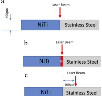
width of 5 m s. Argon gas protection was employed as a shielding gas with a flow rate of 30 Cfh. Fig. 1 depicts the schematic of the different conditions of dissimilar laser welding in a butt joint configuration: (a) laser beam positioned at the interface of both materials, (b) Ni foil with 50 μm thickness inserted between two materials and the laser beam
positioned at the centerline. And (c) laser beam offsetting by 100 μm
from centerline. The 50 μm thickness was the optimum thickness for
inserting Ni interlayer resulted the best mechanical properties, therefore only this thickness will be studied in current study. Also, the reason for aiming the laser beam on stainless steel is due to melting point and thermal diffusivity. Therefore, it is expected that by pointing the laser beam on stainless steel, lower elemental mixing and formation of hard and brittle IMCs in the weld zone occurs. It should be mentioned that other offsetting values resulted in joints with poor mechanical properties or no joint at all.
Microstructural studies were performed on cross sections of dissim-ilar welded specimens prepared by mounting the welded wires in epoxy, grinding up to grit number 1200, polishing by diamond spray down to 0.25 μm and etching with Kroll reagent (2–4%HF, 5–7%HNO3 and
89–93% water by volume). Microstructure observation and phase map were conducted by Olympus BX51 M Optical microscope (OM) and Zeiss Ultra Plus field emission scanning electron microscope (SEM) equipped with Energy dispersive spectroscopy (EDS). Synchrotron XRD performed with a Perkin Elmer 2D detector placed at 1.35 m from the sample with a wavelength of 0.1426 Å (87 keV) at beamline P07 high energy materials science (HEMS) of Helmholtz-Zentrum Geesthacht at PETRA III. A 200 � 200 μm pixel size of a detector with a measured accuracy of
2θ ¼ 0.0084�was used. The raw data images were treated using Fit2D
[32] using the procedure described in Ref. [33]. In these experiments, the probing line started from NiTi base material and ended in stainless steel base material perpendicular to the weld area. The distance between consecutive probed regions was of 50 μm, while the X-ray beam size had
Fig. 1. Dimensions and schematic of 316L Stainless Steel and NiTi in
condi-tions: (a) laser beam on centerline (b) using 50 μm Ni interlayer and (c) laser
50 � 50 μm.
Vickers microhardness testing was carried out to make a series of 200 g indents with a distance of 50 μm between each indent and 10 s
holding time using a CMT Clemex automated hardness tester according to ASTM E384. The strength of the welded samples measured by adopting an Instron 5548 micro tester at a gauge length of 15 mm which includes the weld zone, the heat affected zones and the base materials. All tensile tests were performed at room temperature and a strain rate of 3 � 10 4s 1 and three samples for each welding condition were tested.
3. Result and discussion
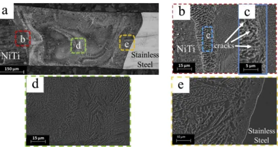
The cross-section microstructure of the laser welded sample without any offsetting is shown in Fig. 2. Full penetration was achieved and both base materials could be distinguished: NiTi (left side) and stainless steel (right side) (Fig. 2a). In addition, a swirling effect occurred inside the weld zone which is related to the Marangoni effect and promotes mixing of the two base materials within the fusion zone. Different densities of the base materials, rapid heating and cooling in laser welding could cause this complex pattern inside the weld zone. Three different regions of the weld zone: NiTi/weld zone interface, inside the weld zone and in weld zone/stainless steel interface are shown in Fig. 2b-d. The NiTi/ weld zone interface in Fig. 2b shows the characteristics of epitaxial growth starting from planar (white dashed line in Fig. 2b), mainly cellular and ended with dendritic structure from base material to weld zone. The cellular interface between NiTi and the weld zone consists of numerous microcracks (Fig. 2c) which were reported elsewhere in this region due to formation of brittle phases [13]. On the weld zone inter-face with stainless steel (Fig. 2e), planar, cellular and dendritic mor-phologies formed in a thinner region and it is due to higher cooling rate during solidification. The microstructure of weld zone in this sample (Fig. 2d) consists of extensive network intermetallics phases in the form of dendritic structure. These intermetallics compounds are the main outcome of mixing elements, especially Ti which formed TiFe2, TiCr2,
TiNi3 and Ti2Ni, and caused extreme brittleness and failure even under
low stress conditions.
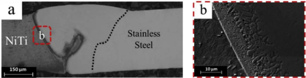
By inserting a Ni interlayer between the two base materials (Fig. 3), a white and sharp interface formed in the interface of NiTi and the weld zone (Fig. 3b). This interface has mainly cellular and cellular dendritic morphologies and, as is reported [15], this white interface is a mixture of TiFe2, TiNi3 and NiTi B2 phases. As is seen, this white interlayer
extended through the entire interface and it is a sign of formation of different types of intermetallics compounds in this condition. In case of
offsetting the laser beam on stainless steel (Fig. 4a) the weld zone ex-hibits different characteristics. It seems that the large network of IMCs is limited to some regions inside the weld zone and its amount reduced considerably. The interface of NiTi and stainless steel (Fig. 4b) became narrower but still consisted of mainly cellular growth characteristics and without visible microcracks. Dendritic structure inside the weld zone formed with finer features in some selected regions inside the weld zone (Fig. 4c). The other important microstructural difference between the joint using the Ni interlayer and the one obtained without laser off-setting (Fig. 2), is the inability to identify the interface of the stainless steel/weld zone. A section of the interface could be characterized (Fig. 4d) with very narrow and sharp interface and very fine equiaxed dendritic structure.
Fig. 5 demonstrates the distribution of Ti, Fe and Ni elements for the different welded joint. As seen in Fig. 5a-c, by focusing the laser beam on the centerline of two base materials, the elements distributed uniformly (especially Ti and Fe which could form several intermetallic com-pounds). In the case of inserting the Ni interlayer, the amount of Fe mixing decreased inside the weld zone (Fig. 5e) compared with the other two conditions as a result of the chemical barrier role of Ni between two base materials. The amount of Ni increased considerably due to the insertion of the Ni interlayer which caused the formation of Ni-based intermetallic compounds inside the weld zone. By offsetting the laser beam onto the stainless steel, Ti content (Fig. 5g) decreased significantly and most of the weld zone consisted of Fe (Fig. 5h) which is the result of stainless steel melting and welding with NiTi. This decrease in mixing of Ti inside the weld pool could cause reduction in the amount of IMCs inside the weld zone which will be discussed further. As a rule of thumb, the higher mixing of Ti and Fe inside the weld zone resulted in more IMCs formation and also when Ni content increased (using Ni inter-layer), Ni-rich IMCs can be preferentially formed.
To identify which IMCs formed in the different welded joint syn-chrotron X-ray diffraction (SXRD) was used. The superimposition of the scans performed from one base material to the other base material are plotted in Fig. 6. Additionally, the intensity variation of one diffraction peak of each one of the IMCs found along the joints was plotted to obtain a qualitative assessment of the volume fraction of each IMC. Overall, various phases are formed inside the weld zone. For the weld centerline condition (Fig. 6a) for instance, from the NiTi base material side to the stainless steel base material side Fe2Ti, Cr2Ti, Fe3Ti and Ni3Ti are formed
and these IMCs are highly brittle and detrimental for the joint perfor-mance [34]. These mentioned variations in different IMCs could be better followed in Fig. 6b in which Cr2Ti and Fe3Ni have higher intensity
Fig. 2. Cross section microstructure of welded sample when the laser beam focused on centerline shows (a) the whole weld zone area, (b) interface of NiTi and weld
Fig. 3. Cross section microstructure of welded sample with Ni interlayer (a) the whole weld zone area and (b) interface of NiTi and weld zone.
Fig. 4. Cross section microstructure of welded sample in 100 μm offsetting laser on stainless steel a) the whole weld zone area, b) interface of NiTi/weld zone, c)
center of the weld zone and d) interface of stainless steel/weld zone.
Fig. 5. EDS mapping of (a-c) centerline, (d-f) inserting Ni interlayer and (g-i) laser offsetting welding welded condition showing distribution of (a, d, g) Ti, (b, e, h) Fe
inside the weld zone when compared to the LOW or Ni interlayer insertion joints. It should be mentioned that these intensities were captured just from the main diffraction peak of each phase. Inserting the Ni interlayer (Fig. 6c and d) however, introduced Ni-rich intermetallics compounds such as Fe3Ni and Ni3Ti. By offsetting the laser to the
stainless steel side, a considerable decrease in IMCs intensity could be visible (Fig. 6e): Fe2Ti peaks reduced and the amount of Ti2Ni, Ni3Ti and
Cr2Ti also considerably decreased. The main peaks intensities of
different phases were clearly visible in Fig. 6f, where stainless steel austenite phase possessed highest intensity inside the weld zone.
The microhardness maps for each weld condition are depicted in
Fig. 7. The microhardness variations are in a good agreement with cross section microstructure and mixing element pattern (Fig. 5). In Fig. 7 a
high microhardness values (with average ~970 H V) could be visible all over the fusion zone and that is due to the homogenous distribution of elements (Fig. 5a-c) and the presence of hard and brittle intermetallic compounds network inside the fusion zone (Fig. 2a). In case of Ni inserted sample (Fig. 7b), higher content of Ti caused higher values microhardness region (red areas). By offsetting the laser beam on stainless steel (Fig. 7c) caused overall lower hardness values inside the weld zone (570 H V) with distributed with different microhardness values pattern. With considering element distribution and phase iden-tification based on SXRD results (Fig. 6), it could be comprehended that the higher Ti in weld zone (Fig. 5d) and also more brittle and hard phases such as Cr2Ti and Fe2Ti resulted in higher values of
microhard-ness. As is expected for all samples, the heat affected zone demonstrated
Fig. 6. Superimposition of synchrotron x-ray diffractograms of (a) centerline joint, (c) Ni interlayer joint welded, (e) laser offsetting joint; and (b, d and f) the
lower values of hardness values due to grain growth of cold worked wires, as also by destabilization of martensite in the stainless steel base material due to the experienced thermal cycles.
Fig. 8 depicts the mechanical properties of welded samples and corresponded base materials. Both offsetting and insertion of the Ni interlayer increase the maximum tensile strength (Fig. 8a) two times. As is mentioned in the introduction section, using Ni interlayer was already an established method for improving joint performance in NiTi/stainless steel dissimilar welding. However, laser offsetting welding has now been shown to have the same enhancement in mechanical properties as colored by green bar in Fig. 8a as a result of hindering the formation of
hard and brittle intermetallics and also by modifying the microstructure in the interfaces of base materials and weld zone. Nevertheless, none of these laser welded samples could reach to required stress level to exhibit stress induced martensite phenomena (Fig. 8b) and even laser offsetting samples failed just before occurring stress induced martensite plateau region for NiTi base material. Fig. 9 showed the fracture surface of welded samples after tensile testing under scanning electron micro-scopy. As could be seen all of the samples exhibited sharp facets and considerable cleavages which is a sign of brittle nature of fracture. However, some dimples and tearing ridges could be observed when the Ni interlayer was inserted (Fig. 9b) and the laser beam offsetting was
Fig. 7. Microhardness values maps for (a) centerline condition, (b) Ni interlayer and (c) laser offsetting welded samples.
Fig. 8. Mechanical properties of NiTi/stainless steel welded samples in different conditions showing (a) Maximum Tensile Strength of the samples, (b) Stress-Strain
applied (Fig. 9c) which is a sign of higher ductility when compared tothe weld centerline sample (Fig. 9a).
4. Conclusions
The current paper adopted laser offsetting welding (LOW) as an effective strategy to enhanced the mechanical properties of NiTi to 316L stainless steel dissimilar welds, by limiting the formation of In-termetallics Compounds (IMCs). In this regard, three different configu-rations were conveyed: (a) positioning the laser on centerline, (b) positioning the laser on stainless steel base material at 100 μm distance
from the centerline and (c) positioning the laser on centerline and using 50 μm Ni interlayer. The results demonstrated that by positioning the
laser beam on the centerline of two base materials, massive brittle intermetallic compounds (such as Fe2Ti, Cr2Ti and Ti2Ni) formed inside
the weld zone due to the uniform distribution of elements. On the other hand, offsetting the laser beam on the stainless steel base material caused less element distribution, thus restricting the intermetallic for-mation. Consequently, microhardness values are non-uniform and lower when the laser was positioned at the weld centerline. The same phe-nomena of decreasing the amount of intermetallics formed, occurred when a 50 μm thickness Ni interlayer was inserted between the two base
materials. However, in this case, mainly Ni-rich intermetallic com-pounds (Fe3Ni and Ni3Ti) formed inside the weld zone. Overall,
off-setting strategy and inserting a Ni interlayer could both increase the mechanical response of the welded samples by suppressing the high hardness and extremely brittle intermetallics, changing their distribu-tion inside the weld zone and modifying the joint microstructure. Therefore, LOW could act as an alternative way for inserting interlayer,
which is a well-known method for improving the dissimilar joint performance.
Declaration of competing interest
The authors declare no conflicts of interest.
Acknowledgements
The authors would like to acknowledge the support of NSERC is Natural Science and Engineering Reseach Council in Canada, Canada Research Chairs (CRC), and also from Fundaç~ao para a Ci^encia e a Tecnologia (FCT - MCTES) for its financial support via the project UID/ EMS/00667/2019 (UNIDEMI). Parts of this research were carried out at PETRA III at DESY, a member of the Helmholtz Association. The research leading to this result has been supported by the project CALI-PSOplus under the Grant Agreement 730872 from the EU Framework Programme for Research and Innovation HORIZON 2020.
Appendix A. Supplementary data
Supplementary data to this article can be found online at https://doi. org/10.1016/j.intermet.2019.106656.
References
[1] W. Predki, A. Knopik, B. Bauer, Engineering applications of NiTi shape memory alloys, Mater. Sci. Eng. A 481–482 (2008) 598–601, https://doi.org/10.1016/j. msea.2006.12.195.
[2] K. Otsuka, X. Ren, Physical metallurgy of Ti-Ni-based shape memory alloys, Prog. Mater. Sci. 50 (2005) 511–678, https://doi.org/10.1016/j.pmatsci.2004.10.001. [3] J. Mohd Jani, M. Leary, A. Subic, M.A. Gibson, A review of shape memory alloy
research, applications and opportunities, Mater. Des. 56 (2014) 1078–1113,
https://doi.org/10.1016/j.matdes.2013.11.084.
[4] J.P. Oliveira, F.M.B. Fernandes, N. Schell, R.M. Miranda, Shape memory effect of laser welded NiTi plates, Funct. Mater. Lett. 08 (2015) 1550069, https://doi.org/ 10.1142/S1793604715500691.
[5] A. Shamsolhodaei, Y.N. Zhou, A. Michael, Enhancement of mechanical and functional properties of welded NiTi by controlling nickel vapourisation, Sci. Technol. Weld. Join. 0 (2019) 1–7, https://doi.org/10.1080/
13621718.2019.1595926.
[6] J.P. Oliveira, R.M. Miranda, F.M. Braz Fernandes, Welding and joining of NiTi shape memory alloys: a review, Prog. Mater. Sci. 88 (2017) 412–466, https://doi. org/10.1016/j.pmatsci.2017.04.008.
[7] Y.N. Zhou, M.D. Breyen, Joining and Assembly of Medical Materials and Devices, Elsevier, 2013.
[8] M.H. Elahinia, M. Hashemi, M. Tabesh, S.B. Bhaduri, Manufacturing and processing of NiTi implants: a review, Prog. Mater. Sci. 57 (2012) 911–946,
https://doi.org/10.1016/j.pmatsci.2011.11.001.
[9] R. Hahnlen, G. Fox, M.J. Dapino, Fusion welding of nickel-titanium and 304 stainless steel tubes: Part I: laser welding, J. Intell. Mater. Syst. Struct. 24 (2013) 945–961, https://doi.org/10.1177/1045389X12461075.
[10] J. Pouquet, R.M. Miranda, L. Quintino, S. Williams, Dissimilar laser welding of NiTi to stainless steel, Int. J. Adv. Manuf. Technol. 61 (2012) 205–212, https://doi.org/ 10.1007/s00170-011-3694-7.
[11] C. Grande, Nickel-titanium alloys welding of thin sheets using GTAW : comparative study between similar and dissimilar welding with AISI 304 stainless, Steel Times 22 (2019) 1–8.
[12] G. Cacciamani, J. De Keyzer, R. Ferro, U.E. Klotz, J. Lacaze, P. Wollants, Critical evaluation of the Fe-Ni, Fe-Ti and Fe-Ni-Ti alloy systems, Intermetallics 14 (2006) 1312–1325, https://doi.org/10.1016/j.intermet.2005.11.028.
[13] J. Vannod, M. Bornert, J.-E. Bidaux, L. Bataillard, A. Karimi, J.-M. Drezet, M. Rappaz, A. Hessler-Wyser, Mechanical and microstructural integrity of nickel–titanium and stainless steel laser joined wires, Acta Mater. 59 (2011) 6538–6546, https://doi.org/10.1016/j.actamat.2011.06.031.
[14] P. Burdet, J. Vannod, A. Hessler-Wyser, M. Rappaz, M. Cantoni, Three-dimensional chemical analysis of laser-welded NiTi–stainless steel wires using a dual-beam FIB, Acta Mater. 61 (2013) 3090–3098, https://doi.org/10.1016/j.
actamat.2013.01.069.
[15] H.M. Li, D.Q. Sun, X.L. Cai, P. Dong, W.Q. Wang, Laser welding of TiNi shape memory alloy and stainless steel using Ni interlayer, Mater. Des. 39 (2012) 285–293, https://doi.org/10.1016/j.matdes.2012.02.031.
[16] S. Fukumoto, T. Inoue, S. Mizuno, K. Okita, T. Tomita, A. Yamamoto, Friction welding of TiNi alloy to stainless steel using Ni interlayer, Sci. Technol. Weld. Join. 15 (2010) 124–130, https://doi.org/10.1179/136217109X12577814486692. [17] H. Li, D. Sun, X. Cai, P. Dong, X. Gu, Laser welding of TiNi shape memory alloy and
stainless steel using Co filler metal, Opt. Laser. Technol. 45 (2013) 453–460,
https://doi.org/10.1016/j.optlastec.2012.06.010.
[18] C.H. Ng, E.S.H. Mok, H.C. Man, Effect of Ta interlayer on laser welding of NiTi to AISI 316L stainless steel, J. Mater. Process. Technol. 226 (2015) 69–77, https:// doi.org/10.1016/j.jmatprotec.2015.06.039.
[19] C. Zhang, S. Zhao, X. Sun, D. Sun, X. Sun, Corrosion of laser-welded NiTi shape memory alloy and stainless steel composite wires with a copper interlayer upon
exposure to fluoride and mechanical stress, Corros. Sci. 82 (2014) 404–409,
https://doi.org/10.1016/j.corsci.2014.01.040.
[20] H. Li, D. Sun, X. Gu, P. Dong, Z. Lv, Effects of the thickness of Cu filler metal on the microstructure and properties of laser-welded TiNi alloy and stainless steel joint, Mater. Des. 50 (2013) 342–350, https://doi.org/10.1016/j.matdes.2013.03.014. [21] A. Shojaei Zoeram, A. Rahmani, S.A.A. Akbari Mousavi, Microstructure and
properties analysis of laser-welded Ni–Ti and 316l sheets using copper interlayer, J. Manuf. Process. 26 (2017) 355–363, https://doi.org/10.1016/j.
jmapro.2017.02.005.
[22] B. Panton, A. Pequegnat, Y.N. Zhou, Dissimilar laser joining of NiTi SMA and MP35N wires, Metall. Mater. Trans. A Phys. Metall. Mater. Sci. 45 (2014) 3533–3544, https://doi.org/10.1007/s11661-014-2280-7.
[23] D. Ruhlig, H. Gugel, A. Schulte, W. Theisen, W. Schuhmann, Visualization of local electrochemical activity and local nickel ion release on laser-welded NiTi/steel joints using combined alternating current mode and stripping mode SECM, Analyst 133 (2008) 1700–1706, https://doi.org/10.1039/b804718a.
[24] Z. Zhu, W. Wang, Y. Li, H. Chen, Effect of laser-arc offset and laser-deviation angle on the control of a Ti-Al interlayer, J. Mater. Process. Technol. 271 (2019) 336–345, https://doi.org/10.1016/j.jmatprotec.2019.04.010.
[25] H.C. Chen, A.J. Pinkerton, L. Li, Fibre laser welding of dissimilar alloys of Ti-6Al- 4V and Inconel 718 for aerospace applications, Int. J. Adv. Manuf. Technol. 52 (2011) 977–987, https://doi.org/10.1007/s00170-010-2791-3.
[26] G. Casalino, M. Mortello, P. Peyre, Yb-YAG laser offset welding of AA5754 and T40 butt joint, J. Mater. Process. Technol. 223 (2015) 139–149, https://doi.org/ 10.1016/j.jmatprotec.2015.04.003.
[27] G. Casalino, S. D’Ostuni, P. Guglielmi, P. Leo, G. Palumbo, A. Piccininni, Off-set and focus effects on grade 5 titanium to 6061 aluminum alloy fiber laser weld, Materials 11 (2018) 2337, https://doi.org/10.3390/ma11112337.
[28] Z. Song, K. Nakata, A. Wu, J. Liao, Interfacial microstructure and mechanical property of Ti6Al4V/A6061 dissimilar joint by direct laser brazing without filler metal and groove, Mater. Sci. Eng. A 560 (2013) 111–120, https://doi.org/ 10.1016/j.msea.2012.09.044.
[29] I. Tomashchuk, P. Sallamand, E. Cicala, P. Peyre, D. Grevey, Direct keyhole laser welding of aluminum alloy AA5754 to titanium alloy Ti6Al4V, J. Mater. Process. Technol. 217 (2015) 96–104, https://doi.org/10.1016/j.jmatprotec.2014.10.025. [30] G. Casalino, P. Guglielmi, V.D. Lorusso, M. Mortello, P. Peyre, D. Sorgente, Laser offset welding of AZ31B magnesium alloy to 316 stainless steel, J. Mater. Process. Technol. 242 (2017) 49–59, https://doi.org/10.1016/j.jmatprotec.2016.11.020. [31] J.P. Oliveira, B. Panton, Z. Zeng, C.M. Andrei, Y. Zhou, R.M. Miranda, F.M.
B. Fernandes, Laser joining of NiTi to Ti6Al4V using a Niobium interlayer, Acta Mater. 105 (2016) 9–15, https://doi.org/10.1016/j.actamat.2015.12.021. [32] A.P. Hammersley, S.O. Svensson, M. Hanfland, A.N. Fitch, D. Hausermann, Two-
dimensional detector software: from real detector to idealised image or two-theta scan, High Press. Res. 14 (1996) 235–248, https://doi.org/10.1080/
08957959608201408.
[33] J.P. Oliveira, F.M. Braz Fernandes, R.M. Miranda, N. Schell, J.L. Oca~na, Effect of laser welding parameters on the austenite and martensite phase fractions of NiTi, Mater. Char. 119 (2016) 148–151, https://doi.org/10.1016/j.
matchar.2016.08.001.
[34] G.R. Mirshekari, a. Saatchi, a. Kermanpur, S.K. Sadrnezhaad, Laser welding of NiTi shape memory alloy: comparison of the similar and dissimilar joints to AISI 304 stainless steel, Opt. Laser. Technol. 54 (2013) 151–158, https://doi.org/10.1016/j. optlastec.2013.05.014.