Study on Gun Drilling Technology in CNC
Machining
Master’s degree in Product Design Engineering
Dhanush Kathiresan
Study on Gun Drilling Technology in CNC
Machining
Master’s degree in Product Design Engineering
Dhanush Kathiresan
Internship Report under the supervision of Doctor João Manuel Matias, Professor at School of Technology and Management of the Polytechnic Institute of Leiria.
This internship report is original, made only for this purpose, and all authors whose studies and publications were used to complete it are duly acknowledged.
Partial reproduction of this document is authorized, provided that the Author is explicitly mentioned, as well as the study cycle, i.e., master’s degree in Product Design Engineering, 2016/2019 academic year, of the School of Technology and Management of the Polytechnic Institute of Leiria, and the date of the public presentation of this work.
I would like to thank all professors of the Mechanical Engineering Department of the School of Technology and Management and to all teachers from other departments for all the knowledge they have given me throughout my journey in this institution, I must thank my professor Joao Manuel Matias for giving me an opportunity to gain exposure and knowledge about molds and Deep Hole Drilling and to complete my report on my internship throughout my course. I would also like to thank all the people from “TECNIMOPLAS” for helping me and passing over their knowledge to me.
This document is the internship report of the Master in Product Design Engineering carried out at Tecnimoplás Lda. The company Tecnimoplás Lda is dedicated to manufacture of molds. They have an ability to make a small, medium and large size molds. Tecnimoplás is a company started in 1971 based in Marinha Grande, specialized in the service of mold.
With this internship it was possible to get the industrial immersion that was the one of the objectives of the student for this stage. In the company after an initial inclosing, it was possible to develop work in the different equipment’s with different materials for mold in the company machines.
This statement is a detailed description and analytical analysis with various processes to make a mold. In this process one of the main process is Deep Hole Drilling. It is also talking about the various types of tools used in deep hole drilling machines and also discuss about the various types of fixing system in deep hole drilling machines. This deep hole drilling is mainly used for Water and Oil circuit in the mold. This report also comprises of case study of Deep hole drilling process and the void formation in the parts of Deep hole drilling machines.
This work also concluded that it is fundamental that the tools used in Deep Hole drilling, are used within the ranges of operation recommended by the tool’s manufacturers.
Keywords: Moulds and its components; Cooling system;
Originality and Copyright ... iii
Acknowledgments ... iv
Abstract ... v
List of Figures ... xi
List of Tables ... xv
List of Abbreviations and Acronyms ... xvii
Introduction ... 1 1.1. Overview of Chapter ... 1 1.1.1. Chapter: 1 ... 2 1.1.2. Chapter: 2 ... 2 1.1.3. Chapter: 3 ... 2 1.1.4. Chapter: 4 ... 2 1.1.5. Chapter: 5 ... 2 1.1.6. Chapter: 6 ... 2 1.2. About Internship ... 2 1.3. Hosting Institution ... 3 About Tecnimoplás ... 5 2.1. Framework ... 5 2.2. Company Characterization ... 5 2.2.1. Location ... 5
2.3. Brief History of Tecnimoplás... 6
2.4. Vision, Mission and Strategic Objectives ... 7
2.4.1. Vision ... 7
2.4.2. Mission ... 7
2.5.1. Project ... 8
2.5.2. Production (Machining, Drilling, Erosion and Assembly) ... 8
2.5.3. Commercial ... 8
About Injection Plastic Industries ... 15
3.1. Injection Moulding ... 15
3.2. Industrial Revolution in Glass moulds ... 15
3.3. Brief Overview of Plastic Industries ... 17
3.3.1. First molds for Plastic Injection method ... 18
3.4. Overview of Injection Molding process ... 19
3.4.1. Molding Process ... 20
3.5. Moulds for Injection of Plastic ... 21
3.5.1. Types of moulds ... 22
3.6. Mould Components and how it works... 23
3.6.1. Movable Half (Ejection Half) ... 24
3.6.2. Spacer Blocks with ejection side base plate ... 25
3.6.3. Ejector Retainer clamping plate ... 26
3.6.4. Ejector Clamping plate ... 26
3.6.5. Ejector Base plate ... 27
3.6.6. Stationary Half (Injection side) ... 28
3.6.7. Base plate in Stationary half ... 29
3.6.8. Clamping plate for the Hot and Cold Runners circuit ... 29
3.7. Injection Molding Machine ... 33
3.7.1. Design of Injection Molding machine ... 33
3.7.2. Clamping Unit ... 35
Mould Cooling System ... 37
4.1. Conventional Straight-Drilled cooling channel ... 37
4.1.3. Conformal cooling channels ... 39
4.2. Remarks for cooling system ... 39
About Deep Hole drilling ... 41
5.1. Specification for Gun drilling ... 42
5.2. BTA drilling ... 43
5.2.1. Specification for BTA gundrill ... 44
5.2.2. Different types of BTA drilling tool ... 45
5.2.3. Deep hole Drilling process ... 45
5.2.4. Rotating Tool ... 46
5.2.5. Rotating Workpiece ... 46
5.3. Highly Productive Gun drill tool ... 46
5.3.1. Single lip Gun drill ... 47
5.3.2. Double Lip Gundrill ... 48
5.3.3. External chip removal method in Gun drill ... 49
5.4. Different types of Drills ... 50
5.4.1. Step Drill ... 50
5.4.2. Core Drill ... 50
5.4.3. Counterboring & Countersinking ... 50
5.4.4. Centre Drill ... 51 5.4.5. Spot Drill ... 51 5.4.6. Spade Drill ... 51 5.4.7. Crankshaft Drill ... 51 5.4.8. Gun Drill ... 51 5.4.9. Trepanning ... 51 5.4.10. Twist Drill ... 51
Case-study on Deep Hole Drilling ... 53
6.1. Fixing System ... 53
6.1.1. Normal Fixing System ... 53
6.2.1. Technical Information about the Information ... 61
6.3. About the Tools... 62
6.3.1. 3D- Tester ... 62
6.3.2. Drilling Tool ... 63
6.3.3. Milling Tool ... 68
6.3.4. Threading Tool ... 69
6.3.5. Chamfer Tool ... 72
6.3.6. Gun drilling Tool ... 73
6.3.7. Conditions: 1 (1.1730/1.2344) ... 75
6.3.8. Conditions: 2 (1.2311/1.2738) ... 77
6.3.9. Condition: 3 (1.2711) ... 80
6.3.10. Condition: 4 (1.2714) ... 82
6.4. Case-Study about Different angle of Intersection Holes... 84
6.4.1. Case-study 1: (Straight intersection hole with 90°) ... 85
6.4.2. Case-study 2: (Cross intersection holes with 45°) ... 87
6.4.3. Case-study 3: (Cross intersection holes with 30°) ... 89
6.4.4. Case-study 4: (Cross intersection holes with 10° to 15°) ... 90
6.4.5. Case-study 5: Feed Rate and Spindle Rotation analysis ... 92
Conclusions ... 95
Figure 1 – Overview of the main production unit... 4
Figure 2 – Company Outlook ... 6
Figure 3 – Tecnimoplás customer by sector ... 9
Figure 4 – Main Customer in Automotive field ... 10
Figure 5 – Business Volume per year ... 10
Figure 6 – Number of moulds manufacturing per year ... 11
Figure 7 – Samag (3-1500) Outlook view ... 11
Figure 8 – Working methodology of Samag (3-1500) ... 12
Figure 9 – Traditional methodology for Glass mould ... 16
Figure 10 – Process for Injecting plastic [14] ... 18
Figure 11 – Main 4 stages of Injection moulding process [27] ... 20
Figure 12 – Injection Mould plastic ... 21
Figure 13 – Two Plate Mould [13] ... 22
Figure 14 – Three Plate Mould [21] ... 23
Figure 15 – Movable Half (Core) ... 24
Figure 16 – Spacer Blocks with Ejector base plate... 25
Figure 17 – Ejector Retainer clamping plate ... 26
Figure 18 – Ejector clamping plate ... 27
Figure 19 – Ejector Base plate ... 27
Figure 20 – Stationary Half (Injection half) ... 28
Figure 21 – Base plate in stationary Half ... 29
Figure 22 – Clamping plate for Runners ... 30
Figure 23 – Whole mould Outlook deign ... 31
Figure 24 – Injection Moulding Machine [8] ... 34
Figure 25 – Parallel cooling channel [8] ... 38
Figure 26 – Serial cooling channel [8]... 38
Figure 29 – Gun drill tool specification [38] ... 41
Figure 30 – Chip removal methodology in gun drilling [38] ... 42
Figure 31 – Gun drill D:d ratios ... 43
Figure 32 - BTA gun drill tool with plackets [39] ... 44
Figure 33 – Single Lip gun drill tool ... 47
Figure 34 – Double Lip Gun drill tool ... 48
Figure 35 – External chip removal Gun drill tool ... 49
Figure 36 – T-slot table holder ... 53
Figure 37 – T-slot holder nuts ... 54
Figure 38 – Bar Clamps ... 55
Figure 39 – Step Clamp ... 56
Figure 40 - Step clamp tools (screws, nuts and clamps) ... 56
Figure 41 – Toe Clamp ... 56
Figure 42 - Pins ... 58
Figure 43 – Female Pin ... 59
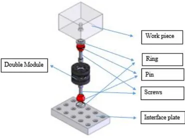
Figure 44 – Fixing Method for Single Module ... 59
Figure 45 – Fixing method for Double Module ... 60
Figure 46 - Heto 2500 Master CNC machine ... 61
Figure 47 – 3D-Tester ... 63
Figure 48 – Rapid Drill ... 64
Figure 49 – Parameters for Rapid drill (Length vs Diameter of tool) ... 64
Figure 50 – Parameters for Rapid Drill (Spindle Speed vs Diameter of the tool) ... 65
Figure 51 – Parameters for Rapid Drill (Feed rate vs Diameter of the tool) ... 65
Figure 52 – HSS drilling tool (HIGH SPEED STEEL) ... 65
Figure 53 – Parameters for HSS tool (Length vs Diameter of the tool) ... 66
Figure 54 – Parameters for HSS drilling tool (Spindle speed vs Diameter) ... 66
Figure 55 – Parameters for HSS drilling tool (Feed rate vs Diameter) ... 67
Figure 56 – Milling Tool ... 68
Figure 59 – Parameters for threading tool vs Pitch of the tool (Fine Pitch) ... 70
Figure 60 – Parameters for Threading tool vs Drilling diameter (Fine Pitch) ... 71
Figure 61 – Comparison between Normal pitch vs Fine Pitch threading tool ... 72
Figure 62 – Comparison between drilling diameter (Normal vs Fine threading tool) ... 72
Figure 63 – Chamfer Tool ... 73
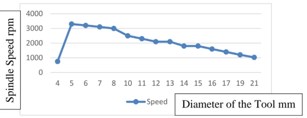
Figure 64 – General Parameters for gun drill tool (Tool diameter vs Spindle speed) ... 73
Figure 65 – General Parameters for gun drill tool (Tool diameter vs Feed Rate) ... 74
Figure 66 – Parameters for Spindle speed vs Tool diameter (Condition: 1) ... 76
Figure 67 – Parameters for Cutting Force vs Tool diameter (Condition: 1) ... 77
Figure 68 - Parameters for Spindle Rotation vs Tool diameter (Condition:2) ... 79
Figure 69 – Parameters for Cutting Force vs Tool diameter (Condition: 2) ... 79
Figure 70 - Parameters for Spindle Rotation vs Tool diameter (Condition: 3) ... 81
Figure 71 - Parameters for Cutting Force vs Tool diameter (Condition: 3) ... 82
Figure 72 - Parameters for Spindle Rotation vs Tool diameter (Condition: 4) ... 84
Figure 73 - Parameters for Cutting Force vs Tool diameter (Condition: 4) ... 84
Figure 74 - Case-study 1: (Straight intersection hole with 90°) ... 86
Figure 75 - Case-study 2: (Cross intersection holes with 45°) ... 88
Figure 76 - Case-study 3: (Cross intersection hole with 30°) ... 89
Figure 77 – Case-study 4: (Cross intersection holes with 10° to 15°) ... 91
Figure 78 – Comparison chart between the Spindle rotation vs Different types of material list ... 92
Table 1 – Cost estimation for different size of moulds ... 9
Table 2 – Technical Information about Samag (3-1500) ... 12
Table 3 – Overview working of Movable half ... 28
Table 4 – Overview working of Stationary Half ... 30
Table 5 – Gun drill tool specification ... 42
Table 6 - Gun drill D:d ratios (Diameter: depth) ... 43
Table 7 - Differentiation table between the Gun drilling and BTA drilling tool ... 45
Table 8 - Highly Productive gun drill specification... 46
Table 9 - Single Lip gundrill specification ... 47
Table 10 - Double Lip Gun drill tool ... 48
Table 11 - Different angles in gun drill tool ... 49
Table 12 – Different sizes for the Bar Clamp ... 55
Table 13 - Technical information about Heto 2500 master ... 62
Table 14 – Comparison table between Rapid Drill and HSS drilling tool ... 67
Table 15 – Specified used parameters in 1.1730/1.2344 ... 75
Table 16 – Parameters for Condition: 1 (1.1730/1.2344) ... 76
Table 17 – Specified used parameters for Condition: 2 (1.2311/1.2738) ... 78
Table 18 – Parameters for Condition: 2 (1.2311/1.2378) ... 78
Table 19 - Specified used parameters for Condition: 3 (1.2711) ... 80
Table 20 - Parameters for Condition: 3 (1.2711) ... 81
Table 21 - Specified used parameters for Condition: 4 (1.2714) ... 83
Table 22 - Parameters for Condition: 4 (1.2714) ... 83
Table 23 – Parameters for Case-study: 1 ... 86
Table 24 – Parameters for Case-study :2 ... 88
Table 25 - Parameters for Case-study:3 ... 90
Table 26 - Parameters for Case-study:4 ... 91
AHA Anibal Henriques Abrantes
APOREM Associacao Portuguesa da Empresses com Museum
CAD Computer Aided Design
CAM Computer Aided Manufacturing
CAE Computer Aided Engineering
CENTIMFE Centro Tecnológico da Indústria de Mouldes Ferramentas Especiais e Plásticos.
CEFAMOL Associacao Nacional da Indústria de Mouldes
CENFIM Centro de Formacao Professional da Indústria Metalurgica e Metalomecanica.
CNC Computer Numerical Control
PME Pequena e Médias Empresas
SIPE Sociedade Industrial de Produtos Eléctricos
BSPT British Standard Pipe Threads
NPT National Pipe Taper
BSW British Standard White worth
UNU Unified National Course
Introduction
This report contains the information about the Internship and the institution where took place the internship. The internship was completed in a company named “TECNIMOPLAS. Ltd”, in this duration internship work/report the guidance was given by Professor João Manuel Matias from the School of Technology and Management of the Politécnico de Leiria. The internship is as a part of the course Masters in Product Design Engineering in IPL, which includes the responsibility of an internship with the duration of about 9 months. During these 9 months, I gathered/learned more information about the Injection moulding process. Along with this, I learned about a specific technology called as “Deep Hole Drilling Technology”. So, in this report there is a separated chapter for the Deep Hole Drilling methodology, void formation in Deep Hole Drilling method and the parameters that affect for the optimisation for the process to make a perfect part.
In internship program started from the conventional saw cutting department at the very beginning. Followed by the Drilling, Erosion, Injection, Assembly and Milling department. The Time spent in each department depended upon the tasks and also the necessary time to understand the main point of the work done in each sector of each department [Conventional saw cutting- 2 weeks, Erosion- 2 weeks, Injection- 1 week, Assembly- 2 weeks, Milling- 2 weeks, Drilling- 6 months & 3 weeks]. In this report there is a brief information about the Moulds and Mould parts at the beginning, after which it has the standard components used to make a Moulds. Explaining all this information from the working experience and knowledge that was gathered during the period of internship. This report concludes with a study of Deep Hole Drilling technology and a case study information about the parameters that affects the Deep hole drilling technology.
1.1. Overview of Chapter
1.1.1. Chapter: 1
In the current chapter it is done a brief explanation to various topics like General Overview of topic, about the internship and its working plan, about the company and main objective of the case study.
1.1.2. Chapter: 2
In second chapter, it contains history of Tecnimoplás and its main objective and characterization, vision & mission and also the framework of the company, finally we discuss about the main customers/dealers for the Tecnimoplás.
1.1.3. Chapter: 3
In third chapter, we are going to discuss the various sectors in mould plastic industries, Historical evolution of glass mould and origin of the injection moulding and about the technical evolution like (First mould for the plastic industry and overview of injection moulding types and its parts), full explanation of injection moulding machine and its design.
1.1.4. Chapter: 4
In fourth chapter, general overview of the cooling system in the moulds and its parts of the cooling system, brief overview of different types of cooling channel.
1.1.5. Chapter: 5
In fifth chapter, in this chapter we are going to discuss about the Deep Hole Drilling process and its types & specification like (chip removal method and Depth-diameter ratios of the gun drill). Different types of gun drills and its angle.
1.1.6. Chapter: 6
In sixth chapter, this a main chapter for this report. It contains case study of deep hole drilling method (First- about the fixing system of the work piece in the machine, Second- setup of the machines and its parameters, Finally- discuss about what are the problems it happens while we do the gun drill process).
1.2. About Internship
This Internship programs aims to contribute to the Deep Hole Drilling process in the moulds industry for plastic injection method, where this process is used to make holes for
the oil and water circuits in the cavities and cores. Is important to note that deep hole drilling is critical in the manufacturing process of the mould, because this is the most economical method of material removal in defining the piece geometry. In this way, most of the pieces passes through this section, so it is considered the heart of the production process in moulding industry. In this context, a process of innovative & sustainable Deep hole drilling when compared to the commonly used in conventional drilling process at that time we can find a different solution and different problems.
In this sector of the moulds, the drilling of the production process is a particularly relevant theme because rethinking the production process not only increases the competitiveness of enterprises through efficient processes, but also contributes to the protection of the environment from a sustainable perspective. Concerns about the environmental impact of the activity contribute to the sustainability of the company, as it enables costs to be lowered and their relationship with the market to be improved. This research focuses on the analysis of different tools strategies (conventional and sustainable) and the measurement of the feed rate and their times through the simulation process. It is intended to determine how the cutting and drilling parameters influence the time of production of moulds with different tonnage and to verify that the proposed drilling strategy, reduces the companies cost and their environmental impact. It is intended, through a process of simulation in software (like Work NC, Top solid) used on a daily basis in the company to create programs to measure the direct effects of drilling strategies simulated in the productive times and the indirect ones in the man-machine hours in the energy consumption in the environment.
1.3. Hosting Institution
The current introduction would take places at my Internship work place. In this chapter it contains the general overview about the work place name is called as the Tecnimoplás. General overview means about the company location and overview of the main production units with different departments.
Tecnimoplás is a company located in Marinha Grande (Embra) established in the year 1971 mainly specialized for Mould making. Mr. Noel Hugo Carlos and Mr. Luis Marrazes through their hard work and dedication developed the company with their efforts, following the footsteps of their parents, the founders of the company. “TO Injection” is a company (specialized in the plastic parts injection) part of the group led by Tecnimoplás. As a service
provider for making moulds the company is committed to meet the requirements of every customer and continuously satisfying all needs. Tecnimoplás is well equipped with latest CNC machine technology with dynamic team, which works tremendously with new and creative ideas. The company has a different department to design and manufacture the moulds like Drilling department, milling department, Erosion department, Grinding department, Design department and Assembly department. In each and every department have a well-trained person to handle issues while they work? Tecnimoplás holds fundamental values such as Honesty, Accuracy and sense of responsibility and all of these are the company mission and vision, company recognizes and appreciates the respect and ethics in human relationship and activities, sprit of team work. Our vision is to provide a good quality moulds for the clients and the mission is to satisfy the customer’s needs. Be competitive in the moulding industry provided better customer satisfaction and also belongs to the main market and be the reference supplier in our market, thus provided continuous improvement of Tecnimoplás organization. Around 80 employees are working in Tecnimoplás.
Figure 1 – Overview of the main production unit
In this chapter contains, little overview about my internship programme and Small introduction about the hosting institution (Tecnimoplás). In further chapter, there is a detail explanation about my hosting institution including the vision, mission and strategic objectives.
About Tecnimoplás
In this chapter it will be described the institution where my internship took place. It contains the company characterisation, overall history about the Tecnimoplás and strategic objectives of Tecnimoplás.
2.1. Framework
The Portuguese moulds sector has around 684 companies with a PME dimension and dedicated to the design, development and manufacture of moulds and special tools; and employs about 8968 workers. Portugal is one of the world’s leading mould producers and is currently exported more than 90% of the total production. Tecnimoplás is thus included in a sector where competition is high in Portugal, but also competition from more developed countries such as Germany, France, Spain, The United States, Canada and emerging China and the eastern European countries. Currently, Tecnimoplás focuses its offer on a set of solutions in the development, Manufacture and testing of injection moulds for plastics, which can be up to 20 tons with simple or complex movements such as sandwich moulds, Multi-component moulds and moulds for assisted injection gas mainly for the automotive market, but also for the packaging electrical/electronic markets.
2.2. Company Characterization
The Tecnimoplás – Industry Technical moulds Ltd is an SME with the economic activity classification, in accordance with the provisions of degree no: 381/2007 of 14 November, CAE: 25734 - metal mould manufacturing based in Marinha Grande with a registered capital of 1,000,000.00 €, its corporate object being the design and manufacture of metallic moulds.
2.2.1. Location
The industrial plant is in the industrial zone it is called as Marinha Pequena Industrial Area, according to the master plan with address in the Leiria road, Apartado 107, Marinha Grande.
Figure 2 – Company Outlook 2.3. Brief History of Tecnimoplás
The company was founded on 1971 in Figueira da Foz, in the production of steel moulds for the plastics injection industry with a capital share of 600,000 €, divided by 6 partners.
At the end of 1974, only three partners were members of the company with equal interests amounting to 600 contos (about 3000€). In 1973 the headquarters of the company was changed from Figueira da Foz to Marinha Grande, where it starts to work in leased facilities. In 1976, already in Marinha Grande there is 18 employees. Tecnimoplás carries out the first direct export, namely a mold for a Wringer for a client from the United States of America.
In 1981, the company acquired the land where it builds the current facilities in Marinha Grande, leaving the company as of 1985 it belongs only to two partners. The land where the industrial establishment is with an area of 9565.50 𝑚2 is bordered to the north by EN 242,
but there is no direct access to that road infrastructure, the bridge with the street of the metallurgical industry, a municipal street that guarantees to access the company. These installations located in an Industrial Zone called the Industrial Area of Marinha Pequena.
In 2007, the two partners retired, passing the management of Tecnimoplás to their children, assuming itself as a success case in the succession of industrial family companies in the sector.
In December 2015, the capital share of the company was changed to fit a renewed strategy of broad management of the value chain, with the founding partners having a share of 5% each and their children with an equal share.
Currently, there are 75 workers in our company with an increase of 2 workers from 2016 – 2017, of which 15% are young graduates in the area of industrial production – IPL Leiria, Mold production – ISDOM Marinha Grande and other degrees.
During its 47 years’ experience Tecnimoplás was a pointer in the adoption of several technologies, it is worth mentioning that it was the first company to have a deep hole drilling center (1988), the first to exploit EDM technologies (1973) and CAD/CAM (1986). Also, at the product level was responsible for innovations where stands out one of the first sandwich molds at the national level, produce in 1984.
The continuous commitment to modernization quality and innovation resulted in the submission of two SI qualification and Internationalization and SME innovation project in QREN, characterized by innovation in the company’s processes, to obtain significant improvement in its performance and thus increase productivity. Another milestone in the company’s life was the certification by NP ISO 9001:2008 in October 2010.
2.4. Vision, Mission and Strategic Objectives
The definition of business strategy formally expressed by the company, based on a clear and objective relationship between vision, mission objective strategy and values, serving as guidance and guidance for all stakeholders.
2.4.1. Vision
The Tecnimoplás vision over the next 10 years, enhance its reputation as a manufacturer of molds and product development of integrated solutions based on innovation reaching the TOP 15 companies in the sector of E & T at national level and strengthen their level of recognized at international level.
2.4.2. Mission
It is to provide customers with high quality complementary products and services, participating in the development and success of their business through the provision of all our know-how. They want to share success with employees and partners and ensure the company’s partners a regular and high return on their investment.
2.4.3. Strategic Objectives
The Strategic Objectives defined reflect a strategic orientation directed towards exports, diversifying the client portfolio both geographically and at sectoral level, increasing the international competitiveness of the company, namely through product innovation with a view to sustainability and growth of the company.
2.5. Market with Customer
The Tecnimoplás is a mold making company, which exports more than 90% of its production, and the critical competitiveness areas as follows:
2.5.1. Project
Fundamental area in the development of engineering solutions that allow to design products and tools differentiating and aggregating added value.
2.5.2. Production (Machining, Drilling, Erosion and Assembly)
Fundamental area, comprising the technologies necessary for the manufacture of moulds, being their fundamental performance, as well as the work done downstream, in the areas of finishing and assembly.
2.5.3. Commercial
The company has a good knowledge of the markets, but the strategic objectives of the company, increasingly demand more dynamism in this area, namely in the field of communication and market prospecting.
The Tecnimoplás favors direct sales, and their client’s injection molding companies, exporting about 90% of its production, mainly for the Automotive– 64%, Home products – 27%, and Glass products – 9%. Mainly Tecnimoplás were concentrated with the automotive mold, because now-a-days the main requirement is automotive. And also, there is a lot of automotive companies are there in the world, so Tecnimoplás mainly focusing in the automotive field. But they concentrate with the other fields such as Home products (Plastic Trays) and Glass products (Wine Glasses). These are the main partition of the Tecnimoplás production rate, percentage values are shown below in Figure 3
Figure 3 – Tecnimoplás customer by sector
The solutions are indicated to produce parts and components with very demanding aesthetic requirement, high precision and rigor dimensions, destined to markets and critical customers, where these molds are subject to aggressive operating conditions and pushed to the limit. In terms of customers, the company sells to large brands such as BMW, AUDI, and MERCEDES among others. In terms of geographical markets, there is a slight variation in recent years with Germany, Israel and the Czech Republic accounting for the most representative figures with the decrease in Switzerland.
The cost estimation for the molds in Tecnimoplás (as shown in Table 1). Always the cost can differ with the size of the molds. Usually in Tecnimoplás produce the three kind of molds such as Large size mold, Medium size mold and Small size mold. But some time the cost getting high compare to this table, because normally they made in this size (for example: if they are going to make a small mold with the lots of complications inside the molds means at that time the cost getting high).
Size of molds Cost € Large 250000
Medium 100000 – 150000
Small 30000 – 50000
Table 1 – Cost estimation for different size of moulds
There are some main customers in automotive field on the Tecnimoplás, such as (Audi, BMW, Mercedes Benz, VW, Mini Cooper, Peugeot). For the Tecnimoplás most the customers from Germany (Audi, BMW, Benz, VW), because main automotive manufacturer is there in Germany. And they have a some other few customers from other countries such as UK (Mini Cooper) and France (Peugeot). Out of 100% almost 85 % of customers from Germany, 10% from UK and 5% from France. The values are shown below in Figure 4
64% 27% 9%
Customer by sector
Automotive Home Appliances Wine GlassFigure 4 – Main Customer in Automotive field
This graphical view is to indicate the Volume of business in Tecnimoplás per every year. It depends upon the size of the mould they manufacture, usually Tecnimoplás concentrating to manufacture a Large mould that is the reason to increase the volume of business. The detailed explanation with discuss below, and graphical view shown the deviation of Business volume (Figure 5)
Figure 5 – Business Volume per year
In Tecnimoplás they produce three different size of moulds such as Large, Medium and Small. Mainly Tecnimoplás are focusing with the large size of moulds in Automotive field. In 2016, totally they produce 32 moulds with different size (17-Large moulds, 10-Medium moulds, 5-Small moulds). These are production rate in year of 2016. In 2017, totally they produce 37 moulds with different sizes (19-Large moulds,10-Medium moulds,8-Small moulds). In 2018, totally they produce 48 moulds (20-Large moulds, 16- Medium moulds, 12-small moulds). These are production rate in Tecnimoplás for Last three years. If you compare with 2016 and 2018 production rate means there is a deviation (shown in the Figure 6), because Tecnimoplás concentrating in the complex moulds.
25% 20% 20% 20% 10%5% Audi BMW Mercedes Benz VW Mini Cooper Peugeot 0 2000 4000 6000 8000 10000 2015 2016 2017 2018 Bussines Volume B usiness Volum e Year
Figure 6 – Number of moulds manufacturing per year
The Tecnimoplás manufactures molds with very tight technical requirement with high quality for very demanding industries. Given the competitive advantage that has Tecnimoplás face to most of its competitors, as well as through those that it intends to develop, the company presents itself to the market based on factors of differentiation namely: Quality, Technical rigor, Term and Extended value chain. The knowledge developed by the company’s R & D center and the market inputs received from customers led the company and re-equated its product offering.
Figure 7 – Samag (3-1500) Outlook view
As explained above in volume of business topic, Tecnimoplás focusing to manufacture a large mold, to increase the production of large mold they are planning to buy a large machine such as SAMAG. In this machine there is plenty of options do to the different kinds of operation such as large inclination holes for the water and oil circuit (+30º to -30º) and long gun drills (up to 1800 mm). This machine is the one of the most important machines in Tecnimoplás to increase the large mold production. All technical information about this machine on shown below in Table:2.
0 5 10 15 20
2018 2017 2016
Large Medium Small Number of moulds
Ye
Figure 8 – Working methodology of Samag (3-1500) Technical Data Units
X-axis maximum 2000 mm Y-axis maximum 1250 mm Z-axis maximum 1250 mm W-axis maximum 2250 mm A-axis maximum ± 30° B-axis maximum 360° Table area 1800 × 1800 mm
Maximum table load capacity 20000 kg
Maximum coolant Pressure 90 bars
Maximum coolant Flowrate 90 L/min
Fixed tool inside the machine 32
Spindle Power 17/25 KW
Spindle Speed 6000 rpm
Spindle Torque 216/320 Nm
Process Milling
Deep hole drilling
Software Heidenhain
Table 2 – Technical Information about Samag (3-1500)
Deep analysis of this machine is it has a high spindle speed and large working space when compare to the other types of deep hole drilling machines, for example (HETO-2500 master) detailed technical information about this machine is explained in following topics.
And also, Samag have a more benefits like improved cooling and air conditioning concept, it has a direct measuring system in all main axis. And one more main advantage is quick change setting for set-up preparations while during the drilling production time. That is why Tecnimoplás like to use this machine, because they are concentrating with a large mould. This machine is properly fixed with this condition.
In this chapter, there is a detailed explanation about the Tecnimoplás including, brief history about Tecnimoplás and their strategies like “who are all the main customers” and “how much they cost for the mould”. And it has a technical information about the Samag, because they contracting to create a large injection mould. In future topics are belong to the Plastic injection moulding and its history.
About Injection Plastic Industries
This chapter contains a brief explanation about the Injection moulding process, Industrial glass mould revolution and about the plastic industries.
3.1. Injection Moulding
Injection moulding is a technique of making an object and producing the object by injecting molten raw material. The raw material is directly injected into the Cavity; it will be manufacture according to the shape of the product. Thereby, the product of the desired shape and material is moulded by injection moulding. In the injection moulding the polymer is heated to a highly plastic state and forced to go into a mould cavity under high pressure, where it solidifies. And then the object is removed from the cavity. This process creates some unique elements. Also, there are many cavity moulds that can be used to create multiple parts in one cycle. Main motive is to produce of moulds. The cost is very important when designed a mould.
3.2. Industrial Revolution in Glass moulds
Glass production industry is a one of the main productions in England for Nearly fourth centuries. There are three main department based on the type of glass production: Windows, Tableware and Bottles. The origin of English bottles is uncertain and even contested in the 17th century. English bottles were clearly existence in the middle of the 17th century [26]. A large number of bottles are made and progressive changes in their form have been used by archaeologist to store the archaeologist deposits they have been found. The earliest bottles were mouth blown, perhaps it made without the help of moulds [40]. The shaping of the glass usually took place at several different stages. The first step is to collect sufficient glass from the furnace at the end of blowing iron. The glass was enlarging to create an oval shape. The oval shape was designed by rolling it on the smooth stone table. And then the oval shape glass is reheated in the oven to produce it into the soft enough surface and also to produce it into required shape [15]. They can further adjust the shape by stretching the glass or rolling it into the smooth stone and for adjust the shape they use the pincers and some other tools. Previously bottles have a universal body with a long neck, the bottom of the bottle was
pushed down to provide a stable base on which the bottle can stand [37]. In later 17th century the bottles were given by short necks and body.
Figure 9 – Traditional methodology for Glass mould
In early 18th century saw the appearance of the short cylindrical bodies, which were certainly made it with the molds. These kinds of molds are simple open cylinder; instead the glass was introduced, blow to fill material to the molds and then it opens vertically. Some bottles of the 18th century with a cylindrical body but slightly wider shoulder was certainly made in such a mold. After the invention for a Bristol glass house indicate that a Brass and Iron bottle molds were, they introduced that on 1970s. Dip molds continues to the manufacturing cylindrical bottles until the middle of the 19th century [36]. In the later period of 18th century the cylindrical bottles were made taller. The creation of the taller bodies may have been aided by the use of hinged two-part molds; However, the earliest illustration of such a mold is 1849 [2].
Henry Ricketts received a patent in 1821 to produce a three-piece mold, which allowed to shape the neck, shoulder and body of the bottles. Ricketts mold allowed to manufacture a bottle with a uniform size, although the capacity was slightly difference as the glass was still collected by hand. Ricketts molds can be used to insert the words and letters into the bottle; many 19th century bottles were made with the letters, which is usually refer to the content of the bottle. The “Finish” (Rim) still is a handmade part, however the late of 19th century a
special pair of tongs was developed which allowed to be shaping the proper deign for the bottle.
In Second half of 19th century a variety of patens were issued to manufacture a bottle with both molds and compressed air [34]. The most famous of these patents were awarded
to Howard Ashley in 1880s for a press and blow machine. Still the glass was collected by the hand and also placed in simple hinged mold. The plunger was used to create a neck by pressing the glass, and then the plunger was removed and compressed air are used to inflate the glass, finally produce the body, the use of this machine allowed a single worker to produce 1560 bottles in a same time, while a traditional group of four can produce 720 bottles [11]. Michael Owens invented an automatic machine in the last decade of the 19th century, that machine can do both collect the glass and made it into a bottle. In this machine had a series of Arms each with a parison and finished molds. As the machine is rotated each hand dipped in to the molten glass and the vacuum absorber is used to collect the necessary glass. The machine was rotated to allow the next hand to collect the glass, after collecting the glass material first arm is inflated using the compressed air to create a bottle [10]. These machines are widely used in the middle of 20th century, although broadly similar machines were
developed (often smaller and cheaper).
3.3. Brief Overview of Plastic Industries
It is best to understand the professionalism covered by molding industries for plastics. Plastics is present in our everyday life in various categories like in Home (television sets, toys, computers, containers for food and kitchen utensils), in Cars (dashboards, stirring wheel, bumpers, etc.), in Hospitals and Health centers (syringes and blood bags), in Protection and Safety devices (goggles, helmets, graves), in food packing (film and plastic bags to preserve it long). So, the man is completely surrounded by materials made up of plastics.
This is the first chemical substitute for the development of chemical industry to provide by second industrial revolution, until the 19th century. It will give birth to the semi- synthetic plastic such as vulcanite, Parke sine, celluloid and celluloid acetate [5]. Then these products are used to replace certain products to produce objects like smoking pipe stem, pins, match boxes, pens, toys, knife handles etc. The first complete synthetic plastics was formed in 1937, it was developed by Leo Baekeland and commercialized under the name of Bakelite. The new material has more features like highly insulating property and is easily designed, it will be allowed to successfully be used in electrical, telecommunication, automobile and radio industries [19]. However, no matter what method to choose, but plastic production is usually three stages:
• Heating (to melt the plastic); • Molding (design the final product); • Cooling (sort the desired shape).
Plastic material and its technologies equipment due to the evolution of its special material such as wood, ceramics, glass, and metals are gradually changed. Following is development, the molding technology is temporarily adapted to respond to rising the claims from the plastic industry. Outline of the injection process of plastics parts [12]:
• Feeding the raw material (plastics) to the injector; • Heating a raw material to soften it;
• Injecting the raw material into the mold; • Extracting the end part.
Figure 10 – Process for Injecting plastic [14] 3.3.1. First molds for Plastic Injection method
Since the making of first injection molds (late 1940s, early 1950s) until the introduction of computer technology in the mold making process (early 1980s), Production of plastic pieces using the injection process usually requires more complex molds that are made of steel to withstand high pressures and temperatures. The first injection molds made in
Portugal were essentially intended for toys, religious figures (saint), and household goods (buckets, bowls etc.). Nevertheless, this phase is not determined by these technologies because at the outset of the exports more pressure was needed to buy new and modern equipment, to answer the rising demand for high degree with plastic pieces. From this movement on there will be mold making for two major groups of plastic pieces: toys (Cars, Airplanes, Boats, Animals, Soldiers, and Dolls among others) and household and decorative items (Tableware, Mirror, Frames, Pots, Sugar bowls, Butter dishes, Trays, Plastic flowers among others). Therefore, among others some of the most important tools are: Pantographs, Precision milling machines, Vertical Grinding machines, Lathes, Lathes for High precision and Shaping [3].
The word associated with this equipment is increasing the need for precise energies and higher mold dimensional accuracy was growing. To meet the need for accuracy, it is important to introduce new devices, especially the milling machines, which allow certain tasks such as steel grinding, which could not be previously done. The will to satisfy the technical demands of these new foreign clients, would have led Mr. Abrantes to purchase, in 1958 “a spark erosion machine that had to be returned because no one was able to operate it [18]. However, it is not enough to achieve the desired perfection to use new devices; because project designer’s work is increasing, they are drawn with the precision drawing. These machines, Mechanical Steel works have been permitted by the use of copper and graphite (electrodes) tools, which are impossible when approaching draft technologies. The process of milling steel using corrosion method is made using steel melt countless and continuous electric discharges, making it to acquire the intended shapes. The introduction of this technology was designed, especially in the machine scales of some of the most complex forms, to reducing the timing of the work and improve the molds and its quality.
3.4. Overview of Injection Molding process
The most commonly used manufacturing process for fabrication of plastic parts is injection molding method. A variety of products are made using Injection molding, which vary greatly in their size, complexity and its applications. In the process of injection molding requires the use of injection molding machinery, Raw material (Molten Plastics) and a mold. The plastic is melted in the injection molding machine and then injected into the mold, where it cools and solidifies into the final parts. In injection molding is mainly used to make a
thin-walled plastic parts, in thin thin-walled parts have a different shape like a cylindrical, cube and complex [23].
3.4.1. Molding Process
The injection process is very short time, usually between 2 seconds to 2 minutes with the following 4 stages,
Figure 11 – Main 4 stages of Injection moulding process [27]
• Clamping unit: Before injecting the plastic into the mould, both parts of the mould must first be securely covered by the clamping unit. And both half of the mould is connected with the injection machine and allows one half to be slide. Usually the hydraulic clamping unit pushes the mould parts together and exerts enough force to safely close the moulds when the material is injected. The time required to fix the moulds is depending on the machine – if its larger machine (those with higher clamping powers) will need more time. This time can be estimated from the dry cycle time of the machine.
• Injection unit: The Raw material, usually in the form of pellets, is injected into the injection machine and progresses to the mould through the injection unit. During this process, the plastic materiel is melted by high heat and pressure. After that the plastic material is injected to the mould with quick movement and creates pressure packs and hold the material. The amount of injected material is referred as the word “Shot”. Due to the complex and dynamic flow of molten plastic, it is very difficult to calculate accurately the injection time. Moreover, the injection time can be calculated by shot size, needle pressure and needle force [23].
• Cooling unit: The molten plastic inside the moulds begins to cool, once it comes in contact with inner mould surfaces. When the plastic cools, it will solidify into the desired area. Moreover, there may be some contraction of the area during cooling. Packing of the material in the infusion phase allows the extra material to flow into the mould and reduce the amount of visible compression. The mould cannot be opened until the required cooling time has passed. The cooling time can be calculated from the many thermodynamic properties of the plastic and the maximum wall thickness of the area.
• Ejection unit: The ejection system in moulding process to push the final part of the mould. They are often used for forcing a solid part out of the mould and they are usually made up of high-quality steel. When the mould opening is complete, the injection machine thick ejector is pushed to the plate. The ejector plate moves forward to guide to moving the ejector guide pin. Ejector pins are tied between the two-ejector plate, so it can be move forward and help to take out the final product of the mould. After we get the product, the needle will move behind the rod. The return pin spring moves behind the ejector plate. The spring and mould closure guide ejector back into the position.
3.5. Moulds for Injection of Plastic
Figure 12 – Injection Mould plastic
A mould is a container prototype, which aims to produce an object with a specific format. There are several categories within the area of mould depend upon the designing technology or raw materials used. The first step in the moulds depending on the injection, pressure, transition, blow technology, thermoforming and circulation. The second step in the moulds thermoplastic, thermoset, rubber, glass and light alloys are classified. A simple steel moulds are thermoplastic injection/plastics consists of two parts: one is the female part (the
Plate 1 Plate 1.1 Cavity (100) Foot Guides Core (200)
Cold Water circuit Hot Water circuit
Plate 9 Spacer blocks
cavity) and other is the male part (the core) both the parts are fits together. Once if both the parts are fitted together there is a space to be given for an accurate thickness in which the fluid (raw material) is injected to the mould. moulds are also produced for various industries with different levels depends on the complexity.
Now-a-days in the mould industries can produce the moulds from automobile to agriculture. However, a personalized mould is not a highly customized tool because serving solely to produce pieces in this case its small or large series for which it was designed. Each mould affects the various construction requirement directly and also it affects the delivery time and cost of the mould. However, it requires a package of geometric and dimensional conditions that require efficient and precise equipment.
3.5.1. Types of moulds
• Two plates Moulds: The Two-plate moulds have a simpler injection system and it has a more advantages. There are two different sides in this type of moulding (A-side & B-side). When this mould is mounded on the injection machine to make part at that time A-side is fixed and B-side is a Movable side [24]. (A-side is a Cavity and B-side is a Core side). Some of the tools are used in two plate moulds are (Locating ring, Guide pin, Return pin, Ejector Guide pin, Support Pillar, Spruce bushing).
Figure 13 – Two Plate Mould [13]
• Three plates Moulds: Three-plate mould is also known as the Small gate mould and one of the differences is additional mould plate is required between Top-clamp plate and Cavity plate, which is called as a Runner plate, it allows the runner scrap and
plastic moulded parts separately. In this type of mould, the plastic particles are injected through the runner and a Gate, this will make easier to remove from the gate area and it gives a finished part. Usually there is a supply channel on the moulds on which the polymer melts into the mould cavity from the tip of the Needle barrel. In that channel consists of Sprue, Runners and Gates [25].
Figure 14 – Three Plate Mould [21]
• Stack Moulds: The stack moulds have a two mould parting surfaces or mould split lines. The stack mould does not require more clamp power than a single-phase mould, because the projected surface area of the cavities on both sides of the centre block cancels the force on each other. The rule of thumb for a clamp force assessment is to take the projected surface area into the melt pressure and multiply it by a factor. Some layered stark moulds have different cavities on each mould splitting surface, and they form a family of parts per shot, each mould varying in shape and size. Some stack moulds can handle different material such as multi-material injections, hard/soft combinations or multi-colour moulding.
3.6. Mould Components and how it works
This is one of the main chapters to know about the mould components and its working, for example, to know how the mould can work in detail manner. The list of mould components is explained below [9]:
• Mould Base; • Mould Cavity; • Mould Core; • Runner System; • Gates & Vents; • Cooling system;
Base plate
Ejector Moulding zone Core
Locating ring
Runners
• Ejection system.
In the whole mould have a different type of plates are fixed (Ejection half (200), Injection half (100), Spacer blocks (5,5.1,6,6.1), Ejector clamping plate (7, 8 and 9), Injection ring holder plate (1) and Runners holding plate (1.1). Each and every plate are explained below in detail manner.
Movable Half : 3 or 3+200, 5, 5.1, 6, 6.1, 7, 8, 9 Stationary Half : 2 or 2+100, 1, 1.1
3.6.1. Movable Half (Ejection Half)
A core is a device used in Casting and Moulding processes to produce the internal cavities with the proper angles. Core insert will have projection and will create hallow portion in plastic component. Core plate usually made up of mild steel material and P20 directly use without hardening after core machining. In Ejection side it has a different stage of plates,
PLATE NO: 200, 5, 7, 8, and 9
These kind of molding blocks are very difficult to manufacture, because in the molding zone there is a lot of works to create an extraction part. Main thing is, it takes a more time to create. As explained above Tecnimoplás always willing to create a complex and large mold.
Figure 15 – Movable Half (Core)
Moulding Zone
One-degree bar
Foot Guides
Moulding Zone: This is the main zone in the moulding parts, because it can hold the
plastic part and create an exact plastic part, that what they need.
One-degree Bar: One-degree bar is mainly used to reduce the friction between the
Injection and Ejection plate while they close the moulds for the injection process.
Foot: While they put moulds in vertical position, it helps to hold the mould.
Guides: This is type of tool is used to fix the mould without any movement, while they
inject the plastic.
Water Circuit: Its mainly is used to cool down the plastic part, while they ejected. But
sometimes in this circuit they use cold water and hot water depends upon the condition of the mould parts.
3.6.2. Spacer Blocks with ejection side base plate
Spacer blocks are used to create a space between the movable clamping plate and the movable tray allows the ejector plate to move, when the area is evacuated. And it has some space for the ejector pins.
Spacer blocks (5, 5.1, 6, 6.1): These blocks are usually to hold the ejector plates and
ejector pins. In between the gap of plate, no:9 and the spacer blocks is used to fix the plates.
Ejector Pin Gap: It helps to move the ejector pin through the movable half (Core) with
the forward and backward movement.
Figure 16 – Spacer Blocks with Ejector base plate
Spacer block :6
Spacer block:5 Spacer block: 5.1
Water Circuit
Ejector Pin Gap Spacer blocks: 6.1
3.6.3. Ejector Retainer clamping plate
In this plate is mainly used to holds the ejector pin, Runners and circular guide. When the mould is closed the ejector, unit is back in its original position with the help of Circular guide.
Figure 17 – Ejector Retainer clamping plate
Circular Guide: This guide needs to be in H7 format, because to avoid the friction with
the circular guide and plate. This type of guides is mainly used to give a up and down movement, while the mould is injecting and ejecting time and also to guide the ejector plate.
Return Pin: Return pins are used to help ensure correct return of the ejector assembly
to the home position.
Ejector Pin: These pins are located on the movable half and the area when the molds
open. Once the mould is open, the pins are extended into the mould cavity, pushing the area out then retract up and allowing the moulds to close and refill.
Spruce Pin: It removes the material from the spruce bushing at the end of the molding
cycle.
3.6.4. Ejector Clamping plate
Clamping plate is used to pushes the ejector pins and reverse pins simultaneously. The ejector was mounted to the retaining plate to create the ejector unit. Additionally, in this plate have a supporting bar placed between the spacer blocks to provide additional support for a movable tray.
Circular guide Return Pin
Ejector Pin
Figure 18 – Ejector clamping plate
Self-Lubricating Bushing: This Bushing is used for the guide pins, to save the time and
money in the design, construction and the operation of injection moulds. These kinds of lubricants are suitable for all applications and also it prohibits the use of external lubricants.
Pry Slot: Locate on the dividing line of the mould body to pry the mold body. This
provides the handling easy, when opening and disassembling a mould.
3.6.5. Ejector Base plate
This plate is also called as a bottom plate, it is mainly used to withstand the spacer blocks and the ejector pin.
Figure 19 – Ejector Base plate
Water circuit Pry Slot
Self-Lubricating Bushing
Water circuit
Ejector Pin gap Supporting Guides
Plate No Working
200 Moulding zone ejection side (To extract the plastic piece after plastic get injected).
5, 5.1, 6, 6.1 Spacer blocks (To create a space to fix the ejector plate and ejector rod).
7 Ejector Clamping plate (Its mainly used to fix the ejector needle)
8 Ejector Plate (conditions are same as the plate no:9)
9 Bottom plate (Its used to hold and fix the moulds in the injection machine)
Table 3 – Overview working of Movable half 3.6.6. Stationary Half (Injection side)
Cavity plate is used to fit with the insert, the cavity plate has a gap to fill the plastic material and form a plastic component. Cavity plate usually made up of Mild Steel Material and P20 directly use without hardening after cavity machining. In injection side it has a different stage of plates,
PLATE NO: 100, 1.1, and 1
Figure 20 – Stationary Half (Injection half)
Moulding zone: This type of molding zone is different from the movable halves,
because in this half have a gap in the moulding zone. Main motive of this half is to create an exact shape of the plastic piece, because this is an injection side.
Guides
Moulding Zone
Water circuit Leader pins
Guides: Usually in the moulds have 4 guides, in each and every side have a 1
-guide. But one of the guides are placed in the centre of the mold, it just dislocated from the centre of the mould, to prevent the dislocation of the moulds while it close.
Leader pin: Its available in the both half’s (Movable and Standard half), main usage
of this pin is to align the both halves of the mold at the parting line.
3.6.7. Base plate in Stationary half
In this plate have a locating ring to locate the centre of the injection machine with a sprue bushing and the tip are aligned. There is a narrow hole through which the material is forced into the runner. It is cut against the tip of the needle.
Figure 21 – Base plate in stationary Half
Locating Ring: Locating ring is placed in the base plate in the Stationary half. And
also, this is a main part in the injection moulding, its helps to inject the plastic raw material into the mould with the help of Injection machine. If one injection process is finished that’s also called as a one shot.
3.6.8. Clamping plate for the Hot and Cold Runners circuit
In this plate has several gaps inside the plate, the gaps are used for to fix the Hot and Cold runner system inside the moulds.
Locating Ring Leader Pin
Figure 22 – Clamping plate for Runners
Hot Runners: In a hot runner system, a multilayer system heats the moulds and sends
the molten plastic to every end, providing the plastic to the various pits within the mould. This type of runners can be heated internally or externally [30].
Cold Runners: In a cold runner system, plastic injection done through the spruce tool.
The plastic fills the runner leading to the cavity.
Plate no Working
100 Moulding zone injection side (To inject the plastic parts through the locating ring)
1 Clamping plate (To hold the locating ring in the bottom of the plate (Injection circle)) 1.1 Clamping plate (To hold the Hot and cold Runners
circuit)
Table 4 – Overview working of Stationary Half
The mold base is a set of steel blocks manufactured with specific dimensions, these dimensions are and can be found into all the mold-base manufactures. Mold sites can be bought from commercial mold base manufactures or produced by mold makers. Basic mold base is in two halves (A and B half). “A” half it is called the standard half (Injection side), and “B” half it is repeatedly referred to as the moving half (Ejection side). A mold Cavity that produces an external appearance or surface area of the mold is usually mounted on A half, while the mold Core that reproduces the inner look of the mold is usually attached to the B half of the mold. Collectively, the Cavity and Core parts are called as the ‘Mold Set’. Molding blocks (Cavity and Core) are usually made from special mold steel or some other materials like Beryllium, Copper, Stainless steel, Aluminum, Brass and other materials such Clamping Gap for the Runners Hot and Cold
Runners circuit
as epoxy. Softer mold materials are commonly used as the prototype molds and for limited product runs. All plastic products have their compact factor, which are compressed to cool and stabilize at a certain rate. Depending on the type of material to be injected, the producers should consider its shrink factor when creating the cavity set.
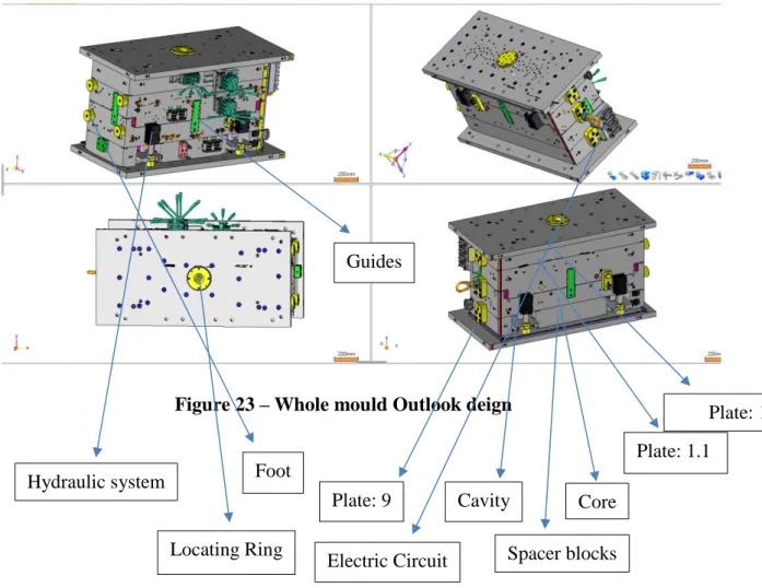
Figure 23 – Whole mould Outlook deign
For example: if the material shrinkage is calculated to be one-hundredth of an inch to six inches long, a total of 6-hundreds of an inch must be added to the design to compensate for the shrinkage. In addition of draft angles or tapers are machined into the side walls of the cavity set to facilitate part removal from the mold. These tapers typically range from 1 degree to 2 degrees per side. Once done, low set heat can be used to protect them from an infusion environment. The molds may also be coated or plated with nickel and hard chrome wear resistant surface material. The middle part of the molds is called as a parting line. Depending on the complexity of the part, there may be many divisions of the parting line. Proper alignment of the mold halves is accomplished by using leader pins and bushings. To avoid mistakes one of the sets leader pin/bushing is dislocated from the metrical position. Now-a-days a more common way is to use a different internal diameter for the bushing and
Hydraulic system Locating Ring Plate: 9 Cavity Spacer blocks Core Plate: 1.1 Plate: 1 Electric Circuit Guides Foot
componently for the leader pin. Due to outside diameter are equal in all the four sets, this allows the plates to be symmetrical regarding this point of view. The mold halves are mounted on parts which are components of the injection machine, most of the injection machines have three parts [16].
• The stationary part, which holds the A half of the mold;
• The movable part, which holds the B half of the mold and moves back and front on the injection machines;
• The rear stationary part, which holds the other end of the bars, thus the entire system; A locating ring in the mold centers to a hole on the fixed area. This then allows the nozzle of the heating cylinder to seat firmly against the sprue bushing on the A half of the mold.
The sprue bushing directs the molten material from the heating cylinder nozzle into the molds runner system.
A mold runner system is a channels or channel network through the material flows to reach the cavity set [30]. Surface runner is the most common runner design, and half circuit channels machined into the surface of mold halves. When the melt thermoplastic flow through the molten system, it reaches the cavity set formed by the interface so called as gate.
The mold gate restricts, and controls flow of plastic in the mold. The path through the gate causes a frictional rise in the temperature of the material, expanding the flow of materials to the molten zone. Common types of gates present in the mold:
• In the Edge gate, it is usually located on the parting line and it is a general gateway; • In the Submarine gate, it brings the material under the parting line to fill the cavity; • In the Tabe gate, it redirects the flow of the material;
• In the Ring gate, it is used in the molding round or cylindrical part; • In the Fan gate, it is used to spread material quickly over a large area.
To remove the air and process gases through injection, a mold venting system is required. The number and size of the vents are determined by Part Geometry, Material Type, Viscosity and the Rate of Injection. These vents are ground on the parting line of the mold. Hot thermoplastic will be under pressure until it gets cool. This cooling system is usually achieved through the cycling of water on the circuit of the mold. Proper cooling contributes to control Part Shrinkage, Part Strength and quality. In totally, the speed of injection of
plastic in the molds is controlled by the efficiency of the cooling system. When parts are sufficiently cool and solid, the movable open and discharge mode generally helps in the form of knockout pins, is used to aid in part ejection. Ejector systems are mounted on the ejection area of the mold, which are usually carried out by Pneumatic and Hydraulic cylinders. In addition to knockout pins, other emission modes include Stripper plates, Stripper Rings and Air Pressure Exhaust. Sometimes a sprue puller is used to remove the plastic from the sprue bushing as a part is ejected.
3.7. Injection Molding Machine
The Injection moulding machine to create a moulded product by plasticize the raw material inside the heating cylinder, injected into the mould and soldering it inside. The moulding machine is built with a mould clamping device that opens and closes the moulding device, and the machine that plasticize the material and inject the moulding material. There are many types of injection machine and their difference is made by how these two devices are organized [22].
• Horizontal Injection Machine: In this type of injection machine both mould clamping devices and injection machine components are fixed horizontally.
• Vertical Injection Machine: In this type of injection machine both mould clamping devices and injection components are fixed vertically.
3.7.1. Design of Injection Molding machine
The Injection machine will be of different types, depending on the type of volume we want, the clamping pressure, the nozzle system and the injection mechanism. In this type of Injection machine mainly it has two units.
• Injection Unit • Clamping Unit


![Figure 11 – Main 4 stages of Injection moulding process [27]](https://thumb-eu.123doks.com/thumbv2/123dok_br/18635579.911408/38.892.277.628.297.592/figure-main-stages-injection-moulding-process.webp)


![Figure 32 - BTA gun drill tool with plackets [39]](https://thumb-eu.123doks.com/thumbv2/123dok_br/18635579.911408/62.892.225.653.419.812/figure-bta-gun-drill-tool-plackets.webp)