Thomas Hauer
[email protected] Institute of Production Management Technology and Machine Tools Petersenstrae 30 64287 Darmstadtl, GermanyMichael Haydn
[email protected] Institute of Production Management Technology and Machine Tools Petersenstrae 30 64287 Darmstadtl, GermanyEberhard Abele
[email protected] Institute of Production Management Technology and Machine Tools Petersenstrae 30 64287 Darmstadtl, GermanyInfluence of a Diagonal Pre-Drilled Hole
on Hole Quality During the Reaming
Process Using Multiblade Tools
The requirements of production engineering for a precision hole are to ensure the required quality as well as minimal production costs. The interactions between machine, tool and the pre-drilled hole result in uncertainties during the final reaming process. For this purpose the reaming process itself and the appearance of process faults were focused in a large number of publications. Due to the fact that the reaming process is an inherent part of a process chain and thus directly linked to a pre-machining process (drilling process), the influence of a pre-drilled hole is neglected till date. For that reason the present paper deals with the influence of a diagonal pre-drilled hole on the reaming process with multi blade tools. Pretests show that the radial deviation of the pre-drilled hole seems to be an important input parameter for the reaming process within the process chain. Based on this new input parameter the question whether the reaming tool follows the path of the pre-drilled hole or not has arisen. To achieve a better understanding of this issue, cutting tests were accomplished to investigate this influence. For this purpose, holes with different radial deviations were manufactured on a five axis machining center and reamed in a second step. The bored holes were evaluated with the help of a coordinate measuring machine and compared with ideal results. Thus the present paper highlights cause and effect relationships within the process chain drilling/reaming. In addition, a further clamping system with an increased stiffness is also examined to decrease the effects of uncertainties. Furthermore, the results were compared with an open loop chip cross section simulation.
Keywords:production engineering, process chain, uncertainties, reaming
Introduction
The manufacturing of precision holes, for example in the automotive or aircraft industry, requires a sequence of several process steps (Abele, Elzenheimer and Tschannerl, 2004). In comparison to a common drilled hole with average tolerances a further manufacturing process is needed to achieve a precision hole with narrow tolerances. Thereby the reaming process pursues the objective to increase the shape of accuracy of the pre-drilled hole (Pauksch et al., 2008). For this purpose two different types of reaming tools can be applied: a single blade reamer or a multi blade reamer. The single blade reamer is characterized by a separation of the guiding and cutting functions. Due to this fact the maximal feed rate of a single blade reamer is restricted to the axial distance between the guiding pads and the blade (Schroer, 2000). The multi blade reamer is characterized by a large number of blades, which are evenly or unevenly distributed around the circumference, and high feed rates (Bhattacharyya et al., 2006; Towfighian et al., 2008). Focusing on cycle times of production sequences and, thus, on the manufacturing costs the application of multi blade reaming tools is one approach to reach higher productivity.
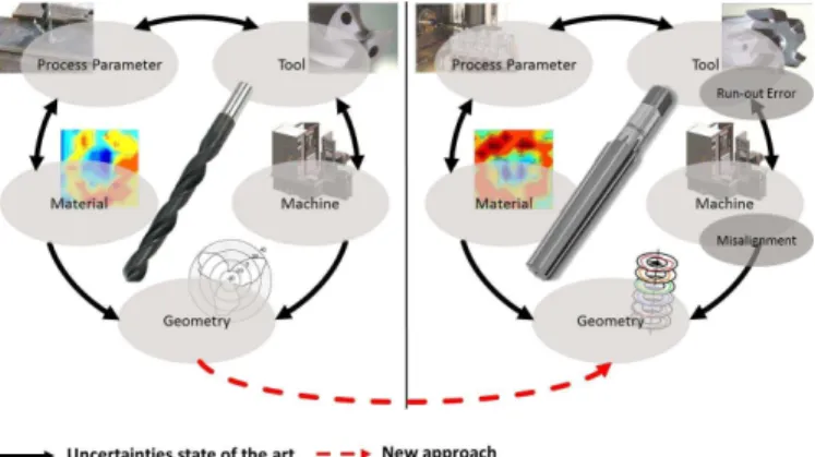
Based on the fact that two consecutive manufacturing processes are necessary to achieve the required tolerances, the reaming process has a large number of input parameters (Bezerra et al., 2001) and, thus, more uncertainties in comparison to the previous drilling process (Fig. 1). The varying input parameters are influencing the width of cut and thus the quality of the reamed hole. The noncompliance of the geometrical demands (tolerances) causes a large quantity of scrap due to an increased added value of the work piece during the pre-machining processes like face milling and drilling. A further uncertainty is a consequence of the interaction between the positional tolerance of the pre-drilled hole and the positioning accuracy of the machine tool. Thus, a misalignment error occurs during the reaming
Paper received 14 May 2012. Paper accepted 1 September 2012.
Figure 1. Abstracted uncertainties for drilling and reaming processes.
also input parameters resulting from the geometric shape of the pre-drilled hole that have not been taken into account till this day. A strength gradient inside the work piece material, for example, leads to different cutting forces at the cutting lips during the drilling process. Thus the occurring imbalances of the cutting forces at the blades bend the tool in one direction. As a result the reaming process has to deal with the uncertainty of a diagonal axis of the pre-drilled hole as an additional input parameter.
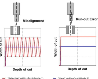
Figure 2. Influence of misalignment error and run-out error on the width of cut during reaming.
In literature as well as in practice the influence of a diagonal pre-drilled hole has not been investigated in detail till date. Without any scientific research or restriction, some authors suggest that the reaming tool always follows the pre-drilled hole. Due to the ignorance of this circumstance the present paper deals with the influence of a diagonal pre-drilled hole on hole quality during the reaming process using multi blade tools.
Pretests to Determine the Radial Deviation
To quantify the radial deviation of different drilling tools and, thus, another uncertainty in the reaming process a first series of tests was conducted. For this purpose a solid carbide drill and a replaceable head drill are investigated. Both tool types have a diameter of 13.8mm. As work piece material a heat-treated steel (42CrMo4V) is
used. The radial deviation of the holes is calculated by the difference between the midpoint of the first and the last circle in a depth of 48mmmeasured during the analysis. According to manufacturer’s data, the cutting speed is 100 minm and the feed rate is 0.18
mm rev for both tool types. A detailed analysis of the radial deviation reveals that the replaceable head drill is deflected up to 0.2mmduring the
drilling process (Fig. 3). The solid carbide drill tends to have a smaller radial deviation because of its increased stiffness. Based on this knowledge, gained during the preliminary experiment, the solid carbide drill was chosen for further experiments, because of the reduced spreading width. Thus, this drilling concept is used to make the diagonal pre-drilled holes. The radial deviation of the pre-drilled holes is achieved by the use of a Hermle C30U, a 5 axis machining center. For this purpose the machine table is pivoted for a certain angle to achieve a radial deviation of 0mm, 0.1 mm and 0.2mm
in a depth of 50mm. After each preparation the work piece is pre-machined with a milling tool to reduce uncertainties by getting a
surface which is perpendicular to the spindle axis. For the reaming process a six fluted reaming tool with a diameter of 14mm, a lead angle of 45 ˚ and an unsupported length of 97mm(length to diameter ratio of 7) is used. Due to a large number of reaming applications in the automotive or aircraft sector, this diameter can be compared with a default value. To minimize run-out errors during the manufacturing process, an adjustable chuck is used. Following the manufacturer’s data, two different feed rates were used (0.3
mm rev and 1.2
mm
rev) because of their importance concerning the mechanical load spectrum during the reaming process and their influence on productivity. Further investigations reveal that rising feed rates lead to increased cutting and passive forces and thus to an increased resultant radial force which bends the reaming tool in case of process faults.
Figure 3. Radial deviation of different drilling tool concepts.
Influence of Diagonal Holes on Hole Quality During Reaming Applications
To determine the hole quality during the reaming process of a diagonal pre-drilled hole, the radial deviation and the roundness first are investigated for a manufacturing process with a straight pre-drilled hole. That means the machine table is not pivoted during the pre-machining of the work piece material. The results, shown in Fig. 4, serve as a reference for following studies with a diagonal pre-drilled hole.
Figure 4. Deviation of a reaming tool along the depth of the hole.
what is shown by the similar deviations of 16 µm (0.3
mm rev) and 18µm(1.2
mm
rev). This can be traced back to the fact that no important process faults arise in this case and, thus, just a small resultant radial force occurs due to the uncertainty of a strength gradient inside the work piece material. The average roundness of the pre-drilled hole decreases during the second manufacturing process, as expected. Its value is only half of that of the pre-drilled hole. The values which are listed in the diagrams are statistically validated with 50 repetitions for each process parameter.
Figure 5. Deviations of a reaming tool for a diagonal pre-drilled hole of 0.1 mm
In Fig. 5 the radial deviation and the roundness of the reamed hole for a 0.1mmdiagonal pre-drilled hole in a depth of 50mmare shown.
In spite of the fact that the pre-drilled holes have a deviation of about 0.1mm, the reaming tools do not change their behavior. According to previous investigations with no diagonal pre-drilled holes, the average radial deviation during the reaming process is 14µmand 19µmfor a feed rate of 0.3
mm rev and 1.2
mm
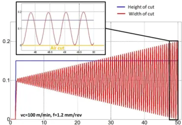
rev, respectively. Thus, the reaming tool does not follow the pre-drilled hole. In this context the orientation of the reamed hole cannot be linked to the deviation of the pre-drilled hole. To get more information about the influence of a pre-drilled hole on hole quality an open loop simulation is implemented. Due to the correlation between the mechanical load spectrum and the area to be cut, a chip cross section model is created. Here, the reaming tool is modeled with the help of even or uneven distributed blades and the lead angle. The pre-drilled hole as well as the path of the reamer in axial direction is discretized depending on a rotating angle. By the fact that the axis of the pre-drilled hole is not aligned with the axis of the reaming tool a search algorithm is used to calculate the width of cut at each time step. For this purpose a procedure is implemented which calculates the difference between the outer point of the cutting edge and a certain number of points on the circumference of the pre-drilled hole. Pre-tests show that the consideration of 10 percent of the circumference of the pre-drilled hole before and after the present blade is a good compromise between precision and computation time. After the calculation of the distance the minimum is chosen for the width of cut at a certain blade. In comparison to the steady state which can be described with a constant chip height the intending process is also taken into account. The increasing width of cut as well as the increasing chip height are calculated with the help of changing distances between the outer part of the lead angle at each blade and the inner part of the discretized pre-drilled hole. In Fig. 6 the calculated width of cut and the chip height are depicted for one blade for a lead angle of 45 ˚ and a diagonal pre-drilled hole of 0.1mm. As
expected, the increasing amplitude has got its maximum at a depth of
50mm. Taking an even greater depth into account, a negative chip cross section will occur which can be linked with the appearance of an air cut. In addition, the calculation reveals the altered behavior of the chip cross section during one rotation and during the whole reaming process. Due to the changing chip cross section at each blade in combination with an uneven spaced reaming tool a resultant radial force acts on the tool.
Figure 6. Open loop simulation of the reaming process with emphasis on the diagonal pre-drilled hole.
A further detail deals with the roundness of the reamed holes. The average values are of the same order of magnitude, compared to the initial situation. But, some roundness progressions show an increase tendency in the last measuring plane during the reaming process. This development can be explained by the initial width of cut and the spreading width of the deviation of the pre-drilled hole. The radial width of cut is set to 0.1mm(half of the difference between the two
diameters 13.8mmand 14mm). This value is superposed with the
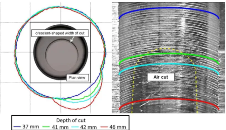
spreading width of the radial deviation, which is mainly influenced by an unknown strength gradient inside the work piece material. Combining these two facts with the assumption that the reaming tool does not follow the pre-drilled hole, an air cut occurs because of the decreasing width of cut at each blade during one revolution. This kind of interruption during the reaming process can be detected with the help of a coordinate measuring machine. If the tactile measuring probe reaches the place of interruption the wall of the pre-drilled hole will be measured. Thereby, the roundness increases because of the shifted center line during the drilling process. Figure 7 schematically shows the transition zone between the continuous and the interrupted cut and their influence on roundness.
The plan view of the reamed hole reveals the crescent-shaped width of cut within one rotation, during the reaming process with a diagonal pre-drilled hole, as an input parameter. Based on this knowledge a further series of tests was carried out with an increased radial deviation (0.2 mm) of the pre-drilled hole. Following the
Figure 7. Transition zone between the continuous and the interrupted cut.
cutting edge and the wall of the reamed hole. This contact zone acts like a resistance for the resultant radial force which is fixed in the direction of the air cut. This area decreases with an increasing depth of cut. If the contact between the secondary cutting edge and the wall is lost, the resultant radial force will bend the tool in direction of the pre-drilled hole. Furthermore, the reaming tool suffers heavy damage at the secondary cutting edge as a result of the interrupted cut in combination with the increased rubbing forces in this area. A further aspect deals with the data computation of the radial deviation. The input parameters contain the center line of each circle measured with the coordinate measuring. Due to the capture of the whole contour of the cross section in a plane the measurement data contain information about the pre-drilled hole. For that reason, a displacement of the center line occurs in the direction of the air cut. This effect can be minimized by an adapted measurement strategy which only takes 180 degrees of the reamed hole into account. The results are reflected in a reduced deviation of the reaming tool during the manufacturing process of about 50 percent for a feed rate of 0.3
mm
rev (30 percent for a feed rate of 1.2
mm rev).
Figure 8. Radial deviation for a diagonal pre-drilled hole of 0.2 mm.
The appearance of an air cut also includes the worsening of the roundness of the reamed hole, as mentioned above. Figure 9 deals with the influence of a diagonal pre-drilled hole of 0.2mmon hole
quality during the appearance of an interrupted cut within the reaming process. A detailed analysis of the roundness during these trials reveals the appearance of two indentations in greater depth which are not in conjunction with low frequency lateral vibrations (Bayly et al., 2001; Friedman, Kitamura and Wu, 1974). A closer look at the mechanic load spectrum, during this phase, reveals that the passive forces at blade one and four as well as the cutting forces almost cancel each other. Thus, the resultant mechanic load spectrum is dominated by the cutting and passive forces at blade five and six because of the air cut at the opposite side. As a result of the lack of
the guiding function at blade two and three, the tool is deviated in direction of the pre-drilled hole. Furthermore, the alternating loads cause considerable wear at the end of the radial land.
Figure 9. Roundness for a diagonal pre-drilled hole of 0.2 mm.
Influence of Diagonal Pre-Drilled Holes on Different Clamping Systems
The increased deviation of the reaming tool during the air cut leads to the conclusion that the stiffness of the tool and the clamping system have got a major influence on hole quality. Due to this assumption, a hydraulic chuck without an adjustable part is used to machine a diagonal pre-drilled hole. A run-out error is minimized by the rotation of the tool inside the chuck before the manufacturing process. Reducing the mechanical load spectrum at the tool tip and at the radial land during the manufacturing process the reaming of diagonal holes with a deviation of 0mm, 0.05 mm and 0.150mm
were investigated. Figure 10 shows the influence of different chucks and feed rates on hole quality. Due to the smaller unsupported length of the second chuck, a decreased deviation occurs as expected. In the majority of cases the increased chip cross section at a feed rate of 1.2
mm
rev leads to an arising shift of the tool tip. The presence of strength gradient inside the material also affects the results shown in Fig. 10.
Conclusions and Outlook
The present paper reveals that the generally accepted statement, that the reaming tool follows the pre-drilled hole, needs to be reconsidered or restricted in literature. The investigations show that a continuous reaming process with tools with a length to diameter ratio of 7 (deep hole reaming) is not influenced by a diagonal pre-drilled hole. An increased deviation of the reaming tool as well as an increased roundness can only be identified by the appearance of an air cut. Thereby the resultant radial force and the lack of a guiding function lead to a worsening of the reamed hole. But a reaming process is not designed to get through an interrupted cut. The present paper is a reference work for many industrial applications in the automotive or aircraft industry which are faced with additional uncertainties like a diagonal pre-drilled hole. Now, the use of a cheap replaceable head drill can be realized with an adapted width of cut during the reaming process, so that no air cut appears. The robustness of the reaming process against a diagonal pre-drilled hole allows the compliance of the required tolerances during the manufacturing process. The calculation of the chip cross section which is shown above can be regarded as an essential part of a closed loop simulation for the reaming process. By adding a force model and a dynamic model, the behavior of the reaming process can be simulated. Based on these results, a robust reaming tool can be developed which minimizes the influence of uncertainties on hole quality.
Acknowledgments
The authors would like to thank the German Research Foundation (DFG) for founding the research activities at the Collaborative Research Center (CRC) 805 – Control of Uncertainty in Load-Carrying Structures in Mechanical Engineering.
References
Abele, E., Elzenheimer, J., Tschannerl, M., 2004, “High Speed Drilling - New Aspects for higher Productivity”, Proceedings of the International Conference on High Speed Machining 2004, Nanjing (CN).
Bayly, P.V., Young, K.A., Calvert, S.G., Halley, J.E., 2001, “Analysis of tool oscilation in a quasi-static medol of reaming”,Journal of Manufacturing Science and Engineering, Vol. 123, pp. 387-396.
Bezerra, A.A., Machado, A.R., Souza Jr., A.M., Ezugwu, E.O., 2007, “Effects of machining parameters when reaming aluminium-silicon (SAE 322) alloy”,Journal of Materials Processing Technology, Vol. 112, pp. 185-198.
Bhattacharyya, O., Jun, M.B., Kapoor, S.G., DeVor, R.E., 2006, “The effects of process faults and misalignemts on the cutting force system and hole quality in reaming”,International Journal of Machine Tools and Manufacture, Vol. 46, pp. 1281-1290.
Friedman, M.Y., Kitamura, I., Wu, S.M., 1974, “Rounding Mechanism of Reaming”,CIRP Annals, Vol. 23(1), pp. 2728.
Koppka, F., 2008, “A contribution to the Maximization of Productivity and Workpiece Quality of the Reaming Process by Analyzing its Static and Dynamic Behavior”, PhD Thesis, TU Darmstadt, Shaker-Verlag, Aachen (GER).
Pauksch, E., Holsten S., Lin, M., Tikal, F., 2008, ’Zerspantechnik” (engl. Machining Technology), Vieweg+Teubner, Wiesbaden (GER).
Sakuma, K., Kiyota, H., 1986, “Hole Accuracy with Carbide-tipped Reamer (2nd Report)”, Bulletin of the Japan Society of Precision Engineering, Vol. 20(2), pp. 103-108.
Schroer, M., 2000, “Reiben von Vergtungsstahl mit Einschnedien-Reibahlen” (engl. Machining of Tempered Steel using Single Blade Reamers), PhD Thesis, TU Dortmund, Vulkan Verlag, Essen (GER).