L.M. Camarinha-Matos et al. (Eds.): DoCEIS 2014, IFIP AICT 423, pp. 451–458, 2014. © IFIP International Federation for Information Processing 2014
Transformer and LCL Filter Design for DPFCs
Ivo M. Martins1, Fernando A. Silva2, Sónia F. Pinto2, and Isménio E. Martins11
INESC-id, Department of Electrical Engineering, ISE, University of Algarve, Faro, Portugal
2 INESC-id, Department of Electrical and Computer Engineering, IST, TU Lisbon, Portugal
Abstract. Flexible AC Transmission Systems (FACTS) can be used for power
flow control in AC transmission grids, allowing simultaneous control of the bus voltage and line active and reactive power. However, due to high costs and reliability concerns, the application of this technology has been limited in such applications. Recently, the concept of Distributed FACTS (DFACTS) and Distributed Power Flow Controller (DPFC) has been introduced as a low cost high reliability alternative for power flow control.
This paper presents the design of a coupling transformer and a LCL filter for DPFC devices. To extract the electromagnetic energy from the transmission line a transformer with a single turn primary is designed and optimized. A third-order LCL filter is used to guarantee high order harmonics filtering. Simulations results are presented and discussed.
Keywords: FACTS, DFACTS, UPFC, DPFC.
1
Introduction
Nowadays the electrical network is facing increasing congestion and loss of reliability. Under this contingency, it is essential to improve the performance of existing power lines and optimize power flow. Flexible AC Transmission systems (FACTS) can be used for power flow control, both in static and dynamic conditions, making transmission systems more flexible [1]. Although FACTS devices offer several benefits, they have not seen widespread commercial acceptance due to a number of reasons [2]. As an alternative approach, the concept of distributed FACTS devices (DFACTS) has been proposed as a lower cost and higher reliability solution [2]. However, since the Distributed Static Series Compensator (DSSC) has no power source, it can only adjust the line impedance and is not as powerful as UPFC.
Using the concept of DFACTS devices, a new concept of distributed power flow controller (DPFC) has been proposed [3] to achieve the same functionality as the UPFC. The DPFC is derived from the UPFC but eliminates the common DC link between the shunt and series converters. As UPFC, DPFC devices give the possibility to control system parameters, such as line impedance and power angle.
After stating the Contribution to Collective Awareness System (section 2) this paper details the operation principle and configuration of DPFC devices (section 3). In section 4 the design of a coupling transformer that extracts electromagnetic energy from the transmission line is presented and in section 5 the design of a third-order LCL filter is shown. Simulation results are presented and discussed in section 6, using switching models of converters connected to the transformer secondary.
2
Contribution to Collective Awareness Systems
This work follows previous research where sliding-mode controllers, based on switched state-space models, to achieve cross-decoupled (independent) control of active and reactive power flow were presented and two different DPFC series converter topologies were proposed [4], [5]. This paper proposes a power transformer and a third-order LCL filter to be part of a DPFC device. DPFC devices can contribute to sustainability of electrical power. This research work on energy management and smart grids might benefit from future collective awareness systems in order to implement cooperative control, or perform informed decision making or the effective involvement of the electrical or sustainable energy systems.
3
Distributed Power Flow Controller
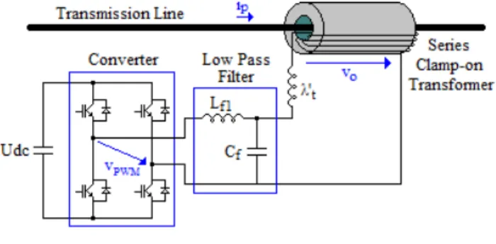
DPFC devices can be used for power flow control in existing transmission lines. Multiple DPFC devices are distributed along the transmission line, cooperating together allowing cross-decoupled control of active and reactive power flow. Each DPFC device (Fig. 1) consists of a power IGBT full-bridge single-phase converter, with a DC capacitor capable to provide the required DC voltage, a series clamp-on transformer to be used in the connection to the transmission line and a low pass filter to reduce the switching frequency harmonics injected into the grid by the converter.
Fig. 1. DPFC configuration
From the conceptual viewpoint each DPFC device can be represented by two controllable voltage sources, connected in series with the transmission line. Each voltage source generates voltage at a different frequency, one at fundamental frequency, vo,1h, and the other at the third-harmonic frequency, vo,3h, so that the
converter output voltage is , , . The voltage source vo,1h injects a
voltage vector with controllable magnitude and phase angle at fundamental frequency, allowing cross-decoupled control of the active and reactive power flow (
P
1h and Q1h).The voltage source vo,3h is responsible to maintain the DC bus voltage (Udc) of the
DPFC converter by using the third-harmonic frequency power. Therefore, using the third-harmonic line current, a controllable voltage vector is injected in series with the line, absorbing or generating active power from the third-harmonic current (P3h).
4
Transformer Design
4.1 Operation Principle
A clamp-on transformer (COT) is used [6] to use the electromagnetic energy of the transmission line. The COT comprises two halves of a cylindrical torus magnetic core surrounding the power line, as shown in Fig. 1. The power line carrying the current ip
acts as the single-turn primary winding of the transformer ( 1), being the secondary winding with ns turns coiled around the magnetic core. The low pass filter
and the AC/DC converter are connected to the transformer secondary terminals. 4.2 Transformer Design
Assuming linear operation and neglecting resistive and leakage voltage drops, the main transformer design equation, which relates the voltage Vp across the primary
winding having np turns, given the maximum magnetic flux density Bmax, frequency fs
and core section effective area Afe, is [6]:
max ,1 ,3 2 (3 ) 6 fe p h p h s p B A V V f n π ≥ + (1)
Selecting the transformer magnetic material and establishing the allowed maximum transformer Bmax value, knowing Vp,1h, Vp,3h and frequency fs, since 1,
the core section effective area Afe can be then calculated.
The transformer primary winding voltage Vp,1h, Vp,3h is the voltage injected in series
with the transmission line by the DPFC device and must be established according to specifications. For design purposes, consider a 220 kV, 300 MVA transmission line with a total of 4500 DPFC devices (1500 devices distributed along one phase) with 0.20 pu line power flow control capability. Each DPFC device must handle
13.3 kVA. This means that the DPFC maximum output voltage at fundamental frequency is , √3 3.1 V, where Zline and Vn are the transmission
line impedance and phase-to-phase voltage at fundamental frequency.
Since the maximum line current is , 787 A, the DPFC output apparent power is , , 2.45 kVA. Considering the phase angle δ of the output voltage Vp,1h as ⁄2 10%, the maximum active power generated by the
DPFC is cos 383 W. This active power generated at fundamental frequency must be equal (neglecting losses) to the active power P3h absorbed at the
third-harmonic frequency. Considering the transformer losses, low-pass filter and DPFC converter, it is assumed 1.5 574 W, where , , . To guarantee a low harmonic distortion of the transmission line current, the injected third-harmonic current Iline,3h should not exceed 10% of the line nominal current
( , 0.1 , ). Thus, from the above conditions, the DPFC maximum output voltage at third-harmonic frequency is , 7.3 V.
To start the transformer design from equation (1), the Bm value must be established
from the material magnetization curve as the highest Bm value before the saturation
zone. Assuming a transformer core using M4 grade Grain-Orientation (GO) 3% Silicon Steel (Si-Fe) laminations, this value is estimated as 1.8 T. Thus, given the required output voltages Vp,1h and Vp,3h, asthe primary number of turns is 1
and the fundamental frequency 50 Hz, the core section effective area can be calculated as 13.9 10 m .
For the calculated Afe value, the size and shape of the core is designed to minimize
the total weight of the transformer (magnetic core and copper windings). To start the design, the secondary winding number of turns ns is set according to the maximum
current and voltage values in the secondary side of the transformer. Making 18 and considering the maximum current density 4 A/mm , the section of the secondary winding wires is chosen as 10 mm2. Therefore, the cross-sectional area of the secondary winding is 180 mm . Taking into account the section of the power line cable 500 mm , the total area of copper in the transformer window is 680 mm . Given the window space factor is nearly 0.33, calculated by the empirical formula 10 30⁄ , where KVhv is the
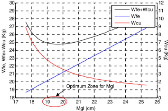
voltage of the secondary winding expressed in kV, the transformer window area is calculated as ⁄ 2.1 10 m . This means that a transformer core with 5.1 cm inner diameter is needed. The core cross-section width around the power line cable and the transformer length can be now sized to optimize the total weight of the transformer. Representing the transformer core dimensions by the core average magnetic path length Mgl, the weight of the magnetic core and secondary winding as
function of Mgl is presented in Fig. 2. As shown, the optimum value for Mgl is in the
range 19-20 cm. Making 19.67 10 m the core outer diameter is 7.4 cm. Given the calculated core section effective area, a 1.2 m long transformer is obtained.
Fig. 2. Transformer weight optimization
5
LCL Filter
In grid-connected applications reduced levels of harmonic distortion are required to comply with IEEE 519-1992 standard. Therefore, a low pass output filter is used to connect the DPFC device to the electric power system (Fig. 1), to reduce the switching frequency harmonics injected to the grid by the DPFC converter.
17 18 19 20 21 22 23 24 25 26 18 19 20 21 22 23 24 25 26 27 28 29 30 Mgl (cm) W fe, W fe+ W c u (K g) 0 1 2 3 4 5 6 7 8 9 10 11 12 W c u (K g) Wfe+Wcu Wfe Wcu
Since between the filter and the grid a transformer is used, which inserts a leakage inductance seen by the grid, the output filter comprises an LC filter plus the transformer leakage inductance ( ), which can be seen as an LCL filter but with constant leakage inductance Lf2 on the output. Neglecting parasitic resistances and
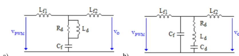
considering the output equivalent impedance seen from the transformer, for the low pass third-order order filter the transfer function is:
1 2 1 2 3 2 2 1 2 1 2 (s ) ( ) ( ) ( ) ( ) ( ) o o f f f o o o f f o o o PW M f o f f f o f f f o L R C L L L L V s L L L R R V s s s s L L C L L L C L L L + + = + + + + + + + + (2)
While the numerator of the transfer function (2) has one real zero set by the output impedance ( ⁄ ), the denominator has one real pole (p1) and two complex
conjugate poles and can be represented by the polynomial
2 , where ξ is the damping factor and ωp the angular passband edge
frequency. Equating the denominator coefficients from (2) with the polynomial d(s), the filter parameters may be calculated from:
2 2 1 1 1 2 1 1 1 2 1 2 2 1 2 (2 ) 2 , , ( 2 ) 2 ( 2 ) 2 (2 ) o p p o o o p f f p p p p f o p p p R p R L p L L L p p p p C R p ξ ω ξω ξ ξω ω ξω ξω ξω ω ξ ω ξω ξ + + − − = = + + + = + + (3)
Usually ξ and ωp are set according to the desired filter characteristics, the pole p1 is
used to cancel z1 and should be placed as near as possible from z1 (ideally ) to
reduce the filter attenuation (| | 20 log ⁄ ) bellow ωp. However, to fulfill
the condition 0 in (3), for a given ωp, the values of ξ and p1 are constrained by
2
⁄ and ⁄ . Setting Lf2 as the transformer leakage
inductance ( 1.55 µH) then ξ and p1 can be established from
2
⁄ and ⁄ .
Setting the passband edge frequency 750 Hz and pole 0.9 ⁄ , the filter parameters are obtained ( 0.15 Ω and 4.9 mH) as 0.55 mH and 91.6 µF.
At the resonant frequency 1 2 4.7 kHz the damping factor of the filter is 3.2 10 and the resonant peak | | 20 log 1 2⁄ 1 2 63.8 dB. The magnitude bode plot of the undamped filter is presented in Fig. 4. 5.1 Damped Filter Design
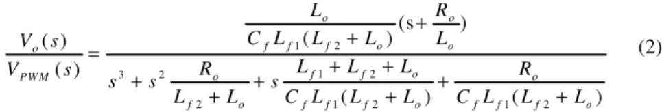
Since passive LCL filters have low damping characteristics at resonant frequency, they can cause instability. Therefore, the filter should be damped to avoid resonances without reducing attenuation at the switching frequency or affecting the fundamental. Several passive damping topologies can be used, each one having its particular properties [7]. Fig. 3 illustrates two practical approaches to damp the LCL low-pass filter.
a) b)
Fig. 3. Practical approaches to the damping of the LCL filter: a) Parallel Rd and Ld in series
with the shunt capacitor. b) Series Rd, Ld and Cd in parallel with the shunt capacitor
5.1.1 Parallel Rd and Ld Damping in Series with the Shunt Capacitor
A damping resistor Rd can be added in series with the shunt capacitor Cf as shown in
Fig. 3a. Since at the resonant frequency the impedance of the filter is zero, the aim of the damping is to insert impedance at this frequency to avoid oscillation. The main drawback of this damping method is that its transfer function contains a high-frequency zero ( 1⁄ ). The addition of Rd degrades the slope of the
high-frequency asymptote, from 40 dB/decade to 20 dB/decade, reducing the filter attenuation above the resonant frequency. Hence, Rd must be chosen so that the value
of z2 is significantly greater than ωr. This condition can be expressed as
1⁄ . Setting the damping resistor impedance at a third of the capacitance at the resonant frequency then 0.77 Ω. The damping factor is now 0.167 and the resonant peak | | 9.6 dB. Fig. 4 illustrates how addition of the damping resistor modifies the magnitude of the transfer function, reducing oscillations in 54.2 dB, but also reducing the filter attenuation above the resonant frequency from
40 dB/decade to 20 dB/decade.
To avoid significant power dissipation in Rd, an inductor Ld can be placed in
parallel with the damping resistor providing a low frequency bypass, as shown in Fig. 3a. To allow Rd to damp the filter, at the resonant frequency the inductor Ld should
have an impedance magnitude sufficiently greater than Rd. However, increasing the
inductance Ld increases weight and energy stored. Thus, the inductor is selected as
4 ⁄ 0.67 mH.
5.1.2 Series Rd, Ld and Cd Damping in Parallel with the Shunt Capacitor
Another approach to damp the filter is to add resistor Rd in parallel with the shunt
capacitor, as illustrated in Fig. 3b. The resistor results in increased power losses, therefore just by itself it is not a practical solution. To obtain the same damping factor as the previous method the resistor is calculated from:
2 1 2 6.9 (p 2 )( ) C f o d f p f o f o L L R C ξω L L R + = = Ω + + − (4)
Fig. 4 illustrates how the parallel damping resistor reduces filter oscillations at the resonant frequency without reducing attenuation above this frequency.
One practical solution to significantly reduce the power dissipation in Rd is to add a
tuned Ld-Cd circuit in series with Rd, as illustrated in Fig. 3b. To allow Rd to damp the
capacitor Cd are chosen such that, at the filter resonant frequency, the impedance of
the damping branch is dominated by the resistor Rd. Therefore, the inductor is selected
as ⁄ 1.5 mH and the capacitor from 1⁄ 31 µF.
Fig. 4. Magnitude bode plot of the LCL filter
6
Simulation Results
The presented transformer and filter with parallel Rd and Ld damping in series with the
shunt capacitor has been modeled and simulated in Matlab/Simulink environment, considering the implementation of the DPFC devices in a transmission network. The simulations values were obtained for a power system consisting of the sending and receiving end voltages Vs and VR, connecting the load Rload, Lload through a
transmission line Rline, Lline, with 4500 DPFC devices (1500 devices per phase).
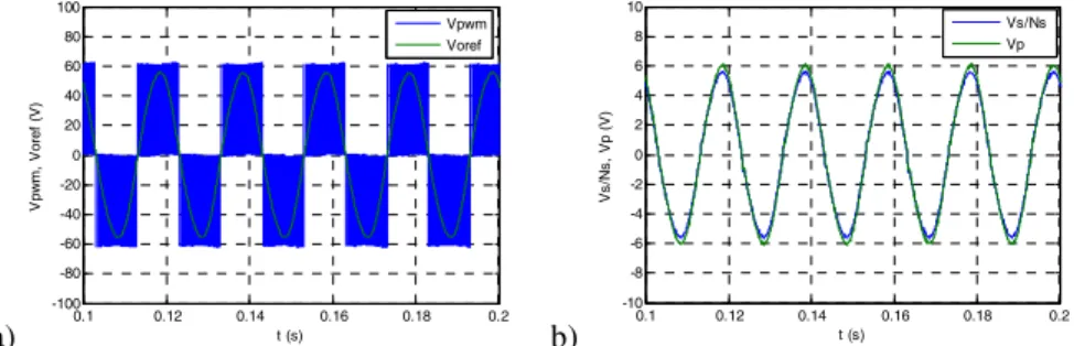
Fig. 5a shows the PWM voltage vPWM injected by the converter and its reference voref. The reference voltage is calculated according to the specified levels of active and
reactive power. Fig. 5b shows the primary and secondary winding voltages vp and vs,
where vs is divided by the secondary winding number of turns ns. As can be noted the
effective transformer turns ratio is not exactly ns/np, due to windings and leakage
voltage drops.
a) b)
Fig. 5. a) Converter PWM output voltage. b) Transformer winding voltages.
0.1 0.12 0.14 0.16 0.18 0.2 -100 -80 -60 -40 -20 0 20 40 60 80 100 t (s) V p w m , V o re f (V ) Vpwm Voref 0.1 0.12 0.14 0.16 0.18 0.2 -10 -8 -6 -4 -2 0 2 4 6 8 10 t (s) Vs /N s , Vp ( V ) Vs/Ns Vp
7
Conclusions
In this paper a power transformer and a third-order LCL filter to be part of a DPFC device was presented. To couple the DPFC device to the transmission line, the transformer is clamped in series with the power line, avoiding galvanic contacts. The LCL low-pass filter interfaces the transformer with the single-phase full-bridge IGBT based converter, to reduce the high frequency switching harmonics. For the designed filter, two passive damping methods were presented. Simulation results were presented showing the effectiveness of the designed transformer and filter.
Acknowledgments. This work was supported by Portuguese national funds through FCT - Fundação para a Ciência e a Tecnologia, under project PEst-OE/EEI/LA0021/2013.
References
1. Gyugyi, L., Hingorani, N.G.: Understanding FACTS: Concepts and Technology of Flexible AC Transmission Systems. IEEE Press, New York (1999)
2. Divan, D., Johal, H.: Distributed FACTS – A New Concept for Realizing Grid Power Flow Control. IEEE Trans. Power Electronics 22, 2253–2260 (2007)
3. Yuan, Z., de Haan, S.W.H., Ferreira, B.: A New FACTS component – Distributed Power Flow Controller (DPFC). In: European Conference on Power Electronics and Applications, Aalborg, pp. 1–4 (2007)
4. Martins, I.M., Silva, F.A., Pinto, S.F., Martins, I.E.: Control of distributed power flow controllers using active power from homopolar line currents. In: IEEE 13th International Conference OPTIM 2012, Brasov, pp. 806–813 (2012)
5. Martins, I.M., Silva, F.A., Pinto, S.F., Martins, I.E.: Independent Active and Reactive Power Control in Distributed Power Flow Controllers (submitted for publication)
6. Silva, F.A., Lopes, D., Sequeira, J.: Designing Transformers for the Power Supply of a Transmission Line Inspection Robot. In: Congrès 2012 CIGRÉ Canada, Montréal, pp. 24–26 (2012)
7. Ahmed, K.H., Finney, S.J., Williams, B.W.: Passive Filter Design for Three-Phase Inverter Interfacing in Distributed Generation. In: Compatibility in Power Electronics 2007, Gdansk, pp. 1–9 (2007)