Using Beryllium and Polypropylene-Aluminium
Absorbers to Measure the TBR-1
Tokamak Electron Temperature
K. A. de Oliveira, A. Vannucci, R. M. O. Galv~ao,
M. S. T. Araujo and I.C. Nascimento
InstitutodeFsicadaUniversidadedeS~aoPaulo CaixaPostal66318-CEP:05315-970,S~aoPaulo,Brazil
ReceivedJune2,1998
Beryllium foils of dierent thickness have been employed for measuring the electron tem-perature in tokamaks using the absorbing method based on ratio of the bremsstrahlung intensities, emited by the plasma. However, in the case of small tokamaks with low electron temperatures, such as TBR-1, the foils must be very thin, becoming very fragile, hard to handle and with insucient absorbing power of line radiation from impurities. Also they are very expensive. In this work, we have investigated whether other absorber materials, obtained by depositing Aluminium on polypropylene lms, for example, could give similar results. These new kind of lters have good mechanical properties and are light tight, as opposed to the thin beryllium foils which have shown, very often, the presence of pinholes. Also, the attenuation of the line emission from impurities, with the use of such lters, is more eective. Silver foils have also been manufactured and used, but with unsatisfactory results due to the TBR-1 low plasma temperature. However, silver foils should be considered a good candidate for measuringT
e through the absorbing method in large tokamaks with
higher plasma temperatures.
I. Intro duction
The controlled thermonuclear fusion is a hope for the mankind of a cheap and inexhaustible source of energy. Towards this goal, intensive eorts have al-ready been spent, during the last decades, in search for processes that could maintain the plasma magnetically conned while its temperature is strongly increased. Among the dierent magnetic connement devices, the tokamak is the one that has achieved the best results up to now.
During the tokamak plasma discharges, several di-agnostics are put in operation to measure the plasma parameters and monitor the plasma conditions. In par-ticular, the soft X-ray detection system has become an important tool to investigate the central part of the plasma column, since the emission of low energy X-rays is closely related to the electron temperature and also the plasma density and impurities. In this paper, the use of pairs of soft X-ray detectors covered with foils of
dierent thickness, for measuring the electron tempera-ture of the plasma conned by the TBR-1 tokamak, will be presented and discussed. Originally, this method of detecting radiation through materials of dierent thick-ness was rst developed for biological purposes by Ja-hoda et al. in 1960 [1]. Latter on, this technique was applied to measure the electron temperature of plasmas magnetically conned and, till now, many works have already been carried out in many dierent tokamaks [2, 3, 4].
exponential functions and also because it is very sensi-tive to line radiation emission from impurities present in the plasma. However, despite these drawbacks, it has already been shown that very good experimental results can be obtained through this technique [3] and it is certainly very much appropriate to be used in small tokamaks like the TBR-1, where only low plasma elec-tron temperature is usually reached.
Traditionally, the thin foils used in front of the soft X-ray detectors are made of beryllium which are rather expensive, extremely fragile ( for low electron temper-ature of the plasma ) and toxic. For this work, a new soft X-ray detection system for the TBR-1 tokamakwas constructed in which dierent type of materials, other than beryllium, were alternatively used to measure the temporal prole of the plasma electron temperature. Initially, the lters were made of silver (obtained by evaporation) because it has the important character-istic of eciently attenuating the VUV line radiation emitted by the plasma impurities (mainly carbon, oxy-gen and nitrooxy-gen). However, these silver lters were not found to be totally adequate for measuring the TBR-1 central electron temperature, as it will be discussed later. Rather, the silver foils should be more suitably used to measure tokamak plasma electron temperatures above 300 eV.
Aluminium deposited in a thin polypropylene lm was then found to be the best choice for an appropriate absorbing material to work with, providing satisfactory results when used to measure the TBR-1 central elec-tron temperature. The Aluminium-polypropylene lter has shown good resistance against mechanical vibra-tions, it is not toxic and attenuates the line radiation more eciently than beryllium; properties that deter-mined its utilization in this work.
In result, the average TBR-1 central electron tem-perature, for plasma discharges that lasted from 8 ms to 10 ms and with plasma current around 12 kA, was measured to be around 130 eV. The corresponding av-erage Ze, using the Spitzer formula, was found to be 3.2, approximately.
II. X-Ray Emission
The soft X-ray spectrum emitted by plasmas magnetically conned in tokamaks is basically com-posed of a continuum and some line radiation peaks
over it. The continuum radiation is formed by two main components:
Bremsstrahlung radiation, produced when
ener-getic electrons interact with the impurity ions or with the hydrogen isotopes.
Electron-ion recombination, related to the capture
of a free electron by the ions in the plasma. In the former process, considering that the speed of the electrons is much greater than of the ions, the interaction rate, that depends basically on the electron temperature (Te) and the production of bremsstrahlung
radiation, on the soft X-ray range, is given by [2]:
W E br /n e X i
niZ 2 iT , 1 2 e e ,E T
e; (1)
where:
W is the radiated power, per cm
3,
correspond-ing to photons in the energy range E.
n
e and ni are the electron and ion densities,
re-spectively.
Z
i is the atomic number of the ions. E is the energy of the emitted photon.
The expression (1) shows that the emission spec-trum has an exponential dependence with the electron temperature and it provides a way of calculating this temperature. Furthermore, since the plasma is hotter and denser at the central part of the plasma column, it can be concluded that most of the X-ray emission will came from this region of the plasma. The soft X-ray de-tecting system turns out to be, therefore, an excellent diagnostic to analyze this part of the plasma column.
W E
r ec
=
W E
br
(,1); (2)
since both emission processes have the same spectrum format. Hence, the parameter reects the enlarge-ment of the bremsstrahlung spectrum due to the re-combination radiation. The energy of the photon that is emitted during the recombination corresponds ba-sically to the kinetic energy of the free electron plus the energy associated with the nal atomic state of the bounded electron.
III. Diagnostic System
The soft X-ray detection system built to mea-sure the electron temperature of the plasma conned by the TBR-1 tokamak is composed of four surface-barrier detectors placed, in pairs, on a ange about 40 cm away from the plasma (Fig. 1). The electronic signals, after the pre-amplication, were digited by CAMAC modules at the sampling rate of 400 kHz.
Figure 1. Soft X-ray detecting system with two pairs of surface-barrier detectors. One pair of detectors views de central plasma column while the other pairs views a region of about 2.0 cm above of the central region.
III.1 Detectors
The surface-barrier detectors (SBD) used, manufactured by ORTEC, have ruggedized frontal elec-trodes made of Aluminium. This type of detector has high detection eciency in the soft X-ray region, good temporal resolution and is easy to manipulate. This semiconductor device is built by evaporating Alu-miniumon the front surface of a thin silicon slab, creat-ing the p-n junction. Each photon that reaches the sen-sitive layer inside the silicon creates a pair hole-electron
for each 3.6 eV of energy that is transferred to the sili-con. The number of photons absorbed in the depletion region, with thickness that is a function of the dier-ence of the potential applied and also of the intrinsic resistivity of the material, depends on the transmissi-bility of the metal deposited in the silicon front surface, on the silicon dead layer and, nally, on the transmis-sibility of the lters that are placed externally in front of the detector [3]. All these considerations must be taken into account to determine how the original spec-tral distribution of the radiation, that come from the plasma, is modied. The specications of the detectors used are:
Aluminium evaporated on the front surface: 0:15
m
Thickness of the silicon dead layer: 0:01 m Thickness of the depletion region: 100 m Polarization voltage (negative): 12 V
Each surface-barrier detectors works essentially as a current source in parallel with a capacitance of about 50 pF (at 12V bias). The detectors are connected, by a short coaxial cable, to current-to-voltage pream-pliers which ultimately determines the frequency re-sponse and, also, the noise performance of the system. The electronic circuits of the preampliers are shown in Fig. 2 and 3. The upper circuit frequency response is determined by the feedback capacitors C1 and C2.
They give a theoretical 3dB bandwith of about 100 kHz, which is suitable to our application. The strongest noise component is due to the thermal noise in the feed-back resistor R1 and also the noise that comes from
the rst stage of the operational amplier. In general, the noise level for LF-357 operational amplier is about 1pA=Hz1
2 in the frequencies of interest [3].
Figure 2. Electronic circuit of the preamplier used to mea-sure the soft X - rays signals using beryllium lters. The inductors were added to reduce de electronic noise.
Figure 3. Electronic circuit of the preamplier used to mea-sure the soft X - rays signals using polypropylene - Alu-minium lters. In this particular case, it was necessary to add one more amplication stage to detect the low intensity signals.
I I I.2 ElectronicNoise
In order to take into account the possibil-ity of picking up some external electromagnetic noises, that could aect our measurements, the hydrogen ll-ing gas ux of the tokamak was turned o after a se-quence of normal discharges, and the capacitor bank was then red. This procedure allowed us to obtain a tokamak discharge with no plasma and it was per-formed, basically, everytime the initial discharge condi-tions were modied. Afterwards, both signals obtained from pulses with and without plasma are subtracted from each other. This subtraction is performed by run-ning a computer code which also calculates, sequen-tially, the ratio of the radiation intensities and which,
nally, gives the temporal prole of electron tempera-ture.
IV. TheAbsorbingFoilsMetho d
The method of measuring the plasma electron temperature by using absorbing foils consists in tak-ing the ratio,R, of soft X-rays intensities measured by
a pair of surface-barrier detectors, with lters of two dierent thicknesses placed in the optical path of the detectors, each one viewing the same thermal region of the plasma column through equal solid angles (Fig. 4).
Figure 4. Illustrative sketch of the experimental arrange-ment with a pair of surface-barrier-detectors viewing the same thermal region of the plasma column.
The use of this method is based on two basic as-sumptions: rst, the intensity of the bremsstrahlung
radiation per unit of wavelength interval, emitted in the X-ray region by the hot plasma, varies exponen-tially with the electron temperature andsecond, the
X-ray mass absorption coecients are energy depen-dent, and the coecients, for several dierent materi-als commonly used as lters, are experimentally known and can be found in the literature [5].
R = R exp[,hc T e , F 1x F 1 , AlxAl
,
SixSi]Ef() ,2d R exp[,hc T e ,
F2xF2 ,
AlxAl ,
SixSi]Ef()
,2d; (3)
where:
mass absorbing coecient of the used materials.
xlters thickness.
wavelength of incident radiation.
Ef() = 1
,exp(,0:01 Si)
eciency of the
de-tector.
hc1:2398 (eVm).
The integrals in equation (3) can be easily calcu-lated, if a smooth function that gives the mass absorb-ing coecient for each of the incident radiation wave-lengh can be found. It is already known that the best t for the mass absorption coecient of the materials obtained from reference [5], in the wave length interval up to 0:01 m, is of the type [6]:
() = A:(B +Cln); (4)
where:
wavelength of incident radiation.
A, B and Cadjustable parameters.
The numerical calculation of the expression (3), writting the mass absorption coecients as equation (4), was done for 30 arbitrary Tevalues from 50 to 300 eV ,
considering the lter thicknesses shown in table 1:
Foils Thicknesses in (m)
xF
1 x
Al
1 x
Si xF
2 x
Al
2 x
Si
Be 0.20 0.15 0.01 0.50 0.15 0.01 Ag 0.33 0.15 0.01 0.52 0.15 0.01 Poly. + Al 0.84 0.16 0.01 1.05 0.30 0.01 Thicknesses of used lters for numerical calculations employed.
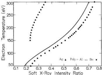
The adjusted curves for
R
(third degree polyno-mials) were obtained for dierent type of lters used in this work, and are showed in Fig. 5. Note that in this gure the ratioR
varies monotonically with the electron temperature values, for beryllium and polypropylene-Aluminium foils, providing a good dis-crimination in the range 100-300 eV, in relation to theX-ray ux experimentally measured. However, we don't nd the same performance with silver foils.
Figure 5. Electron temperature versus soft X - ray intensity ratio, for beryllium foils (circle symbols), polypropylene -Aluminium foils (continuous line) and silver foils (triangle symbols). The calculated points were adjusted by a poly-nomial function of the third degree.
V. Manufacturing the lters
The absorbing foils that replaced the beryl-lium lters, for this experiment, were constructed at thePhysicsInstituteoftheUniversityofS~aoPauloand
at the InstituteforAdvancedStudies (IEAv). Dierent
techniques were used to obtain each kind of foil. The thickness of the lters were previously estimated, in each case, as to give the best (R x Te) curve slope for the TBR-1 electron temperature range.
V.1 Silver Filters
Silver lters with thickness of about 0:30 m and 0:50 m were obtained by standart deposition tech-nique and mounted in a circular support, as a free standing foil. The exact thickness of the foils were sured by placing them in a vacuum chamber and mea-suring the energy lost by incident Alfa particles [7, 8].
V.2 Aluminium Coated Polypropylene Films
lm, caused by the reecting light interference. Precise values of the thicknesses and also good homogeneity of the lms are important factors for the accuracy of the method. Quantitatively, the thickness of the foils were obtained by analyzing the interference fringes that re-sult from the superposition of the light reected in both surface boundaries of the polypropylene lm. Hence, the index of refraction and the thickness of the lm could be obtained by using a spectrophotometer which measures the light transmitance in relation to the wave-length, or wave number, of the incident photons. The equipament used for this purpose was a Lambda 9 UV - Visible - Near Infrared spectrometer where two radi-ation sources, a deuterium lamp and a halogen lamp, covered the working wavelength rang of the espectrome-ter [9]. The analysis of the spectrum obtained indicated how uniform were the plastic supports obtained by ex-trusion. Fig. 6-a, for example, shows the spectrum obtained for a very homogeneous lm while, in Fig. 6-b, the spectrum obtained for a non-homogeneus lm is observed. Note that, in the latter case, the maximum and minimum peaks are not well dened.
This method of analysis allowed the measurements of the thickness
h
and the refractive indexn
of the polypropylene lms to be obtained using the following relation, for normal incidence of the light [9]:h = m4n; (5)
where:
hthickness of the plastic lm.
minterference order.
wave number of the monocromatic
inci-dent light.
nindex of refraction of the plastic lm.
The index of refraction of the material can be ob-tained directly from the spectrum by using the expres-sion:
n =
s
1 +p
1,T
1, p
1,T ;
(6) where T is the intensity radiation transmited through the plastic lm.
We have calculated the refractive index for 15 polypropylene lms and obtained < npoly > = 1:47
0:02. This value is in very good agreement with the
result found in the literature: 1,49 [10].
Figure 6. Spectrum obtained with a homogeneous polypropylene lm (a), when only one color is observed to be reected from the plastic lm surface, and spectrum obtained with a non-homogeneous polypropylene lm (b), when several colors are observed to be reected from the plastic surface.
Polypropylene lms were covered with Aluminium by standart deposition technique, with dinamic thick-ness deposition control (quartz cristal oscillation) [7].
V.3 The transmissivity of the Filters
7-b, and 7-c, respectively. As it can be observed, beryl-liumlms (Fig. 7-a) are not suitable to be used for mea-suring low temperature plasmas, due to the large exist-ing transmissivity window between 30 eV and 70 eV, where most of the line radiation is more likely to exist. In this respect, silver lms (Fig. 7-b) seem to be more appropriate to attenuate the V.U.V. emission. How-ever, they do not apropriately discriminate the plasma electrons temperature in relation to the radiations in-tensity values obtained, i.e., small changes in the soft X-ray intensity ratio yields very large changes in Te
val-ues (Fig. 5). For polypropylene plus Aluminium lms (Fig. 7-c) the transmissivity in this range of energy is decreased by an order of magnitude, indicating that these lter are appropriate to be used in smalltokamaks such as the TBR-1.
VI. Experimental Results
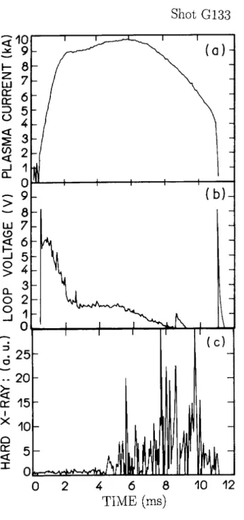
Figures 8-9 and 10-11 show the basic experi-mental signals (plasma current (Ip), loop voltage (Vl),
central soft X-ray (rx) and hard X-ray (RX) obtained for two dierent plasmas pulses. The discharge shown in Figures 8-9 corresponds to a maximum plasma cur-rent of about 10 kA, that lasted for about 7 ms. In this discharge the central electron temperature was mea-sured during the at top portion of the plasma current, using beryllium and silver foils. The results obtained are presented in Fig. 12 and Fig. 13. As one can see, with berillium foils the central electron tempera-ture pratically remains the same (Te
140 eV ) along
the 2 ms of the current plateau. After that, Te could
not be calculated because strong bursts of hard X-ray emission were observed, related to the formation of run-away electrons (Figure 8-c), which turned this method of analysis impracticable. The central electron temper-ature measured using silver foils are presented in Figure 13. As we can see, the temperature prole is very dif-ferent from the one that measured by using beryllium foils, althought both X-ray signals have been simulta-neously measured. Analysing the Figure 5 one observes that the calibration curve, for silver foils presents a very high slope that explain the many oscillations observed in the electron temperature prole. This might explain, also, the large electron temperature value (300 eV )
which is unrealistic for small size tokamaks as the TBR-1. Figure 14 shows the central electron temperature ob-tained with polypropylene-Aluminium foils. As we can see, the obtained Teprole presents many oscillations,
reecting the strong uctuations observed in the raw
soft X-ray signals. However, the average value of about 130 eV is more realistic and it is in a fair agreement with the results obtained with the beryllium lms.
Figure 7. (a) Transmissivity of beryllium foils: 0:20 m
(continuous line) and 0:50 mthickness (dashed line);(b) silver foils: 0:33m(continuous line) and 0:52 m thick-ness (dashed line); (c) polypropylene-Aluminium foils: 0:84
Figure 8. Plasma current (g.a), loop voltage (g.b) and hard X-ray (g.c) from plasma pulse G130.
Figure 10. Plasma current (g.a), loop voltage (g.b) and hard X-ray (g.c) from plasma pulse G133.
Figure 11. Soft X - ray signals measured by a pair of detec-tors which view a central region of the plasma column with polypropylene - Aluminium foils (gs: (d) and (e)).
Figure 13. Electronic temperature of the central plasma column obtained by the absorber method using silver foils.
Figure 14. Electronic temperature of the central plasma col-umn obtained by the absorber method using polypropylene - Aluminium foils.
Conclusion
For this work, very suitable soft X-ray l-ters were obtained by evaporating Aluminium over a polypropilene lm, which replaced, with advantages, the imported beryllium lters that have been utilized for measuring the TBR-1 electron temperature. Con-trary to beryllium, the Aluminium-polypropilene lter are very strong against mechanical vibrations, easy to manufacture, non-toxic and considerably much cheaper. Experimentally, the TBR-1 electron temperature measured by the two foils method, using the new l-ters, ranged from 100 - 130 eV for tokamak operation conditions: plasma current: about 10 kA, plasma dis-charge: approximately 8 ms, gas lling pressure: 6;0x
10,5 mbar. The TBR-1 central electron temperature
measured with the Aluminium-polypropilene lters re-sulted to be somewhat smaller than the temperature obtained by using the beryllium foils. If one consid-ers that very thin beryllium ltconsid-ers usually have very tiny holes which may aect all the calculations and, also, that beryllium is not so ecient to absorb the line radiation emitted by the impurities, then it is reason-able to accept that the values obtained with the use of Aluminium-polypropilene lters are more precise. The corresponding average Ze for the TBR-1 plasma, us-ing the Spitzer formula, was found to be 3.2, approx-imately. The silver lms, although being as simple to obtain as the Aluminium-polypropilene lters, were not considered to be a good choice for measuring the elec-tron temperature of low temperature plasmas, because of the (Te x R) slope, which is too steep for tempera-tures bellow 300eV. This kind of lter, however, may
give good results for plasmas with electron temperature above 300eV.
Acknowledgements
The authors are grateful to the sta of the Laser Laboratory of the UNICAMP, where measurements of the polypropylene thickness were done, and to IEAv, for the helpful advisements about Aluminium deposi-tion on the polypropylene lters.
References
[1] F.C.Jahoda, E.M.Little, W.E.Quinn, G.A.Sawyer and T.F.Stratton; Phy. Rev.119, 843 (1960).
[2] S. von Goeler, Diagnostic for Fusion Experiments, Pergamon Press, N.Y., 79-109 (1979).
[3] M.Malacarne, I.H.Hutchinson,Soft X-Ray Imaging Di-agnostic on the HBTX IA Reversed Field Pinch, Cul-han Laboratory Report, CLM-R 227, England (1982). [4] A.Vannucci et al., Nucl. Instr. and Meth. Phys.
Re-search,A280, 593 (1989).
[5] B.Henke at al, Atomic Data and Nuclear Data Table,
1, 27 (1982).
[6] L.Nenu, E.Cojocaru, I.N.Mihailescu,Filter Method for Electron Temperature Determination from X-Ray Con-tinuum Radiation Emitted by Hot Plasmas, Report LOP-10-80, Bucharest (1980).
[8] J.F.Dias and M.N.Martins,ManualparaMedidade Es-pessura de Alvos por Irradiac~ao de Partculas Finas,
Laboratorio do Acelerador Linear Report, IFUSP/P-839, Brasil (1990).
[9] M.Born and E.Wolf,PrinciplesofOptics, 5
th edition,
Pergamon Press, Oxford, (1975).
[10] CRC Handbook of Chemistry and Physics, 58th