Experimental Analysis of the Fault Tolerance of the
PIM-SM IP Multicast Routing Protocol under GNS3
Gábor Lencse
Department of Telecommunications Széchenyi István University
Győr, Hungary
István Derka
Department of Telecommunications Széchenyi István University
Győr, Hungary
Abstract—PIM-SM is the most commonly used IP multicast routing protocol in IPTV systems. Its fault tolerance is examined by experimenting on a mesh topology multicast test network built up by Cisco routers under GNS3. Different fault scenarios are played and different parameters of the PIM-SM and of the OSPF protocols are examined if they influence and how they influence the outage time of an IPTV service. The failure of the Rendezvous Point (RP) of the given IP multicast group as well as the complete failure of a router in the media forwarding path of the multicast stream are examined. A method is given how the service outage time caused by the complete failure of a router can be limited by an appropriate choice of the Dead Interval parameter of OSPF.
Keywords—IP multicast protocols; PIM-SM; OSPF; fault tolerance; GNS3; modelling and simulation
I. INTRODUCTION
Protocol Independent Multicast – Sparse Mode [1] (PIM-SM) is the most commonly used multicast routing protocol in IPTV systems. The customers of these systems expect uninterrupted entertainment, which requires fault tolerance from the transport network. PIM-SM allows only one Rendezvous Point (RP, see later) per multicast groups [2] thus the RP can be a critical part of the multicast network. PIM version 2 introduced a fault tolerance mechanism with the help of the bootstrap mechanism [3]. This mechanism makes possible for a multicast based IPTV system to survive the failure of the RP; however the switching over to the new RP is not always invisible for the customers, but may cause service outage for a certain amount of time. In our previous research papers [4] and [5], we investigated the possible length of the service outage time and the parameters it may depend on. Different scenarios were investigated and parameters were tested whether they have an influence on the length of the service outage time, and if so, how they influence it. The measurements were performed on a mesh topology network built up by four times four XORP [6] routers. However, the behaviour of the fault tolerance of the PIM-SM implementation in the tested XORP system might depend on implementation specific details. In our current research, we performed our previous tests again using Cisco images under GNS3 [7] to validate our previous results.
The remainder of this paper is organised as follows. First, an introduction to the operation of PIM-SM and a very brief summary to IPTV systems are given. Second, the test
environment is described. Third, the different kinds of experiments are presented and the results are interpreted. Fourth, the directions of our future research are outlined. Finally our conclusions are given.
II. INTRODUCTION TO PIM-SM AND IPTV SYSTEMS The following descriptions are the taken from our previous paper [5] with some shortening. For a more detailed description with illustrative figures, see our original paper or [8].
A. The Operation of PIM-SM
Protocol Independent Multicast builds multicast trees on the basis of routing information obtained from a unicast routing protocol (e.g. RIP, OSPF) – this is why PIM is called “protocol independent”. It has four variants, from which we deal with PIM-SM only. PIM-SM [9] does not suppose group members everywhere in the network but it sends multicast traffic into those directions where it has been requested using unidirectional shared trees rooted at the Rendezvous Point
(RP). It may optionally use shortest path trees per source. PIM-SM does not have an own topology discovery method, but uses the Routing Information Base (RIB) of the unicast routing protocol applied in the Autonomous System (AS). With the help
of this "outer" Routing Information Base (RIB), PIM-SM
builds its own Multicast Routing Information Base (MRIB).
Unlike unicast RIB (that specifies the next router towards the destination of the packets) MRIB specifies the reverse path from the subnet to the router.
As PIM-SM is an Any-Source Multicast (ASM) protocol,
the receivers need to find the source(s). The so-called
Rendezvous Point (RP) is used for this purpose. The RP can be
set statically by the administrator of the AS, or it can be elected from among the RP candidate routers. There can be only one RP per multicast groups in the AS (or multicast domain) at a time.
The operation of PIM-SM has three phases. Now, we briefly describe what happens in these phases.
1) Phase One: RP-Tree
The Rendezvous Point Tree (RP-tree) is being built in the
following way. The receivers send their IGMP (or MLD) Join messages with the required group address as destination IP address. The Designated Router (DR) of the receiver (that was
of the required multicast group. This PIM Join message travels through the routers in the network and the visited routers prepare the appropriate MRIB entries thus the RP-tree is being
built. The PIM Join messages have the marking: (*, G), where the first element is the IP address of the streaming source and the second one is the IP address of the multicast group.
The star (“*”) means that when a receiver joins a group, it will receive the traffic from all the sources that send steam to multicast group G. The PIM Join messages do not need to travel until the RP; it is enough to reach a point where the RP-tree has already been built. (The RP-RP-tree is also called shared tree because the multicast traffic from all the sources uses the same tree.) The PIM Join messages are resent periodically while there is at least a single member in the group. When the last receiver of a leaf network leaves the group then DR sends a (*, G) PIM Prune message towards the RP so as to cut back the
tree until the point where there are other active receivers connected.
When an S data source starts sending to a group, the first hop router (DR) of the source encapsulates the data packets of the source into unicast messages called Register messages and
send them to the RP. The RP router knows from the Register messages that the source is ready to send the stream. The RP decapsulates the Register messages, and forwards the contained streaming data message to the appropriate multicast group (if it has at least a single member) using the RP-tree.
Note that the multicasting is fully functional at end of phase one; the following two phases serve efficiency purposes only.
2) Phase Two: Register-Stop
The RP sends an (S, G) Join message to the source. As this message travels to the source, the routers along its path register the (S, G) pair to their MRIB (if they do not have it yet). When this Join message arrives to the subnet of the source (S) or to a router that already has an (S, G) pair registered in its MRIB, then the streaming data start flowing from the S source to the RP by multicast routing. Now, a source-specific multicast tree
between the S source and the RP was built. After that, the RP sends a Register-Stop message to indicate that the first hop
router of the source does not need to send Register messages (encapsulating the multicast data packets into unicast messages).
3) Phase Three: Shortest-Path Tree
The path of the packets from the source to the receivers through the RP may be not optimal. To eliminate this, the DR of the receiver may initiate the building of a source specific shortest-path tree (SPT) towards the source (in this way
possibly leaving out RP from the path). To do this, DR sends an (S, G) Join message to S. When this message arrives to the subnet of S or to a router that already has an (S, G) pair, then the streaming data start flowing from S to the receiver using this new SPT.
Now, the receiver receives all the streaming data packets twice. To eliminate this, the DR of the receiver sends an (S, G) Prune message towards the RP. (This is also known as an (S, G, rpt) Prune.) This message will prune the unnecessary tree parts and the streaming data will not arrive to the receiver through the RP-Tree any more.
4) The Built-in Fault Tolerance Mechanism of PIM-SM
It is an important element of the fault tolerance of PIM-SM that the RP does not need to be set up manually, it can be automatically elected from among those PIM-SM routers that were configured Candidate RP (C-RP).
The election uses the bootstrap mechanism described in [10]. The BSR router is elected dynamically from among the
PIM-SM routers that were configured Candidate BSR
(C-BSR). All the C-BSR routers flood the multicast domain with their Bootstrap messages (BSM). The one with the higher
priority wins. During the BSR election all the routers – including C-RP routers – learn the IP address of the BSR. After that, all the C-RP routers send their Candidate-RP-Advertisement (C-RP-Adv) messages to the BSR periodically.
(The C-RP-Adv messages are sent in every C_RP_Adv_Period
seconds, the default value is 60 seconds.) The BSR collects these messages, builds an RP list and advertises it also periodically for all the routers. The list is encapsulated into a BSM and is sent in every BS_Period seconds. All the routers –
including the BSR and the C-RPs – can decide the winner RP
by the priority of the C-RPs. If the current RP fails to send its C-RP-Adv message to the BSR within RP Holdtime (a value
included in the C-RP-Adv message) then BSR decides that it is dead and starts advertising the new RP list leaving out the dead one.
Notes:
1) Ref. [10] says that the RP candidate routers should set RP Holdtime to a value that is not less than 2.5*max{BS_Period, C_RP_Adv_Period} so that the system is able to tolerate the loss of some Bootstrap messages and/or C-RP-Adv messages.
2) The C-BSR routers also take care if the elected BSR fails, but that is not addressed in this paper.
3) The Choice of the Underlying Unicast Routing Protocol
As PIM-SM is protocol independent, there is a certain
freedom in the choice of the underlying unicast routing protocol. The two most widely used protocols are the Routing Information Protocol [11] (RIPv2) and the Open Shortest Path First [12] (OSPFv2) for routing within a single autonomous system. Even though RIP is much simpler and more widely used in LANs than OSPF, it is not scalable and therefore it is not appropriate for the size of networks that are often used for providing IPTV services. This is why OSPF was chosen for our test network.
Note that OSFP also uses a fault tolerance mechanism but it is much simpler than that of PIM-SM. The OSPF routers take care for their neighbours only. All the OSPF routers send Hello
messages in every Hello Interval seconds to their neighbours. If
they do not see a Hello message from a neighbour within the so called Dead Interval time they consider the given neighbour
dead and they calculate new routes leaving out the dead neighbour.
B. IPTV in a Nutshell
DVB-S/S2 via satellite, DVB-T/T2 via terrestrial, DVB-C/C2 via cable TV links and so on. In the TCP/IP based networks, the commonly used solution for delivering the digital video, audio and auxiliary data is based on the DVB-IPTV [13].
A general property of the above mentioned technologies is that they use the same MPEG2 Transport Stream (MPEG2-TS) format to organize the digital data (video, audio, etc) and additional service information (SI/PSI tables) into a common frame. The MPEG2-TS is divided into 188 bytes long packets (4 bytes header and 184 bytes data). In the IPTV environment, usually seven TS packets are embedded into one IP/UDP or IP/UDP/RTP packet and they are sent through the network. Unlike other DVB technologies, IPTV does not use broadcasting to deliver these packets. Instead, it uses IP multicast for the live or online streaming (e.g. live TV) and unicast for the offline services, for example VoD or Timeshift.
When a subscriber would like to watch the selected IPTV program his/her receiver joins to the TV program's pre-programmed IP multicast group. After the join process (a few seconds) the receiver will get continuously the MPEG2-SPTS packets of the TV program through the IP multicast enabled network. If the subscriber switches over to another IPTV program then the receiver will leave the current one and join to the next IP multicast group.
III. TEST ENVIRONMENT
In our previous paper [5], a mesh topology network was used in a virtualized environment with XORP [6] routers. Now the same topology is used and the GNS3 [7] environment was chosen for our experiments.
For our experiments, one Sun Server SunFire X4150 was used with the following configuration: two Quad Core Intel
Xeon 2.83GHz CPUs, 8GB DDR2 800MHz RAM, 160GB HDD, Gigabit Ethernet NICs.
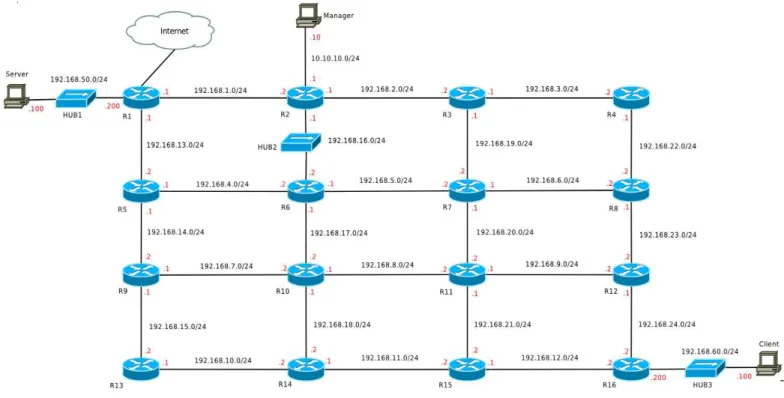
The topology of the test network was a mesh network built up by 4 times 4 virtual Cisco 7200 routers interconnected via Gigabit Ethernet point-to-point links as shown in Fig. 1. There were some further devices used: three virtual computers and three virtual hubs. The virtual computers were realized as Virtualbox virtual machines with 1GB RAM and 10GB HDD per virtual machine. The computers called Server and Client were used for media streaming, and the one named Manager was used for both managing the experiments and monitoring the traffic. For this reason, it had direct connections to all the three hubs (but the lines were omitted from the figure for aesthetic and clear-cut considerations). The usage of the hubs was inevitable for monitoring for the traffic and it also helped to keep away the management traffic from the mesh network.
The virtual computers had Ubuntu 12.04 LTS operating system. As for media streaming, the VLC software of VideoLAN was used for both server and client purposes.
A. IP Configuration
Private IP addresses were used from the 192.168.0.0/16 network. The IP addresses of the virtual routers were configured manually as shown in Fig. 1. The network segments between two routers displayed by horizontal and vertical lines got IP addresses from 192.168.{1-12}.0/24 and 192.168.{13-24}.0/24 networks respectively. The last octets of the IP addresses of the interfaces are written next to the interfaces. The IP addresses of the network segments connecting the server and the client virtual computers are displayed in a similar manner. Plus the Manager computer had additional IP addresses from the subnets it was connected to (through hubs).
B. OSPF Configuration
Because of the nature of the mesh, the OSPF protocol could be configured by the definition of peer-to-peer connections (it can be done if the neighbouring routers are interconnected by point-to-point links).
The typical general OSPF configuration commands were (they belong to R2):
router ospf 20
router-id 192.168.1.2 log-adjacency-changes
network 192.168.1.0 0.0.0.255 area 1 network 192.168.2.0 0.0.0.255 area 1 network 192.168.16.0 0.0.0.255 area 1
And the typical interface configuration fragment for an interface looks like follows (it belongs to an interface of R2): interface GigabitEthernet1/0
ip address 192.168.2.1 255.255.255.0 ip ospf network point-to-point ip ospf cost 1
ip ospf hello-interval 10 ip ospf dead-interval 40 negotiation auto
Configuring OSPF in this way made the network fully connected: unicast IP packets can be sent from anywhere to anywhere. Note that PIM-SM uses the unicast routing table (RIB) when building its own multicast routing table (MRIB).
C. PIM-SM Configuration
For PIM-SM, those and only those interfaces should be configured where PIM-SM has to handle multicast traffic. A typical configuration for an interface looks like follows: interface GigabitEthernet1/0
ip pim sparse-mode
In order to be able to experiment with the fault tolerance of PIM-SM, the dynamic election of the RP was used. This required us to configure some routers as C-RP and at least one router as C-BSR. Routers R2, R4 and R14 were configured as both C-RP and C-BSR but with different priorities1.
The R2 router was the highest priority C-RP, the R4 was the second highest priority one; R14 was the highest priority C-BSR. A typical configuration for a router that was set as both C-RP and C-BSR looks like follows:
ip pim bsr-candidate GigabitEthernet1/0 1 2 ip pim rp-candidate GigabitEthernet1/0 priority 2
Considering the fact that in phase three there is no need for the RP, but a source-specific shortest path tree (SPT) is used for the transmission of the stream (that may not contain RP, or even if it contains RP then RP acts like a simple multicast router only), PIM-SM was configured so that it would never enter phase three:
ip pim spt-threshold infinity
1As it is defined in [9], the lower numeric value means higher priority.
D. Time Synchronization
The important events of the measurements were logged into text files. In order be able to compare the timestamps of the events occurred on different virtual routers or computers, the system times of the other virtual routers and computers were synchronized to R1 using the standard NTP protocol. The R1 router had an Internet connection and it was synchronized to a stratum 1 time server in the Internet. The configuration of R1 had the following commands:
ntp master 3
ntp server 130.149.17.21
The other routers had the following command: ntp server 192.168.1.1
E. Streaming
A single program transport stream (SPTS) – that was demodulated and demultiplexed from a Hungarian DVB-T multiplex – was pre-recorded and used for all the measure-ments. The VLC server sent the stream to the 239.1.1.1 multicast IP group address using UDP. The VLC client received the stream and the standard tshark program was
used by the Manager virtual machine to capture (and record for offline analysis) the stream on the receiver side through HUB3.
IV. EXPERIMENTS AND RESULTS
A. Testing the Failure of the RP
Hypothesis 1: Killing the RP on R2 router will not stop the
stream (unlike it was stopped when XORP was used [5]) because Cisco PIM-SM fully complies with the PIM-SM standard [9] and thus the RP functionality is no more needed at the end of phase two.
The measurements were controlled by a script executed on the Manager virtual computer. The RP functionality was switched off by the remote execution of the following commands on the R2 router:
no ip pim bsr-candidate GigabitEthernet1/0 1 2 no ip pim rp-candidate GigabitEthernet1/0 priority 2
The experiments were executed multiple times and we did not experience service outage. We have also checked that R2 stopped functioning as an RP and R4 was elected as the new RP.
B. Testing the Failure of the Complete PIM-SM router
Hypothesis 2: Switching off the operation of the complete
Then it waited until PIM-SM sent a C-RP-Adv message. From that time it waited until a predefined delay (it was a
parameter, see later). After that it started the scripts and it sent a marker (ICMP echo request) to the client and then it remotely switched off both unicast and multicast routing functionality of R2 by shutting down of its network interfaces.
The following commands were used:
access-list 100 deny ospf any any interface GigabitEthernet1/0 ip access-group 100 in ip access-group 100 out shutdown
interface GigabitEthernet2/0 ip access-group 100 in ip access-group 100 out shutdown
interface GigabitEthernet3/0 ip access-group 100 in ip access-group 100 out shutdown
Note that the filtering out of all the OSPF messages was necessary because otherwise the OSPF running on R2 would have notified its neighbours (using OSPF LSA updates). However, our aim was to simulate not the regular shut down but the failure of R2.
The predefined delay was increased from 5 seconds to 55
seconds in 5 seconds steps. (As C-RP-Adv is sent in every 60 seconds by the defaults settings of the Cisco IOS, thus there would be no point in increasing the delay above 55 seconds.) The whole measurement was executed 11 times. The complete script can be found in the Appendix.
The results can be found in Fig 2. They justify hypothesis 2: the stream stopped for a while and it continued after a certain amount of time; the service outage time shows no correlation with the time elapsed from the last C-RP-Adv message. Both prove that no new RP is necessary for the restoration of the stream.
Hypothesis 3: The length of service outage time caused by
the switching off the operation of the complete R2 router depends on the time elapsed from the last Hello message of the
OSPF protocol.
The default values of the OSPF Hello Interval and Dead Interval are 10 seconds and 40 seconds respectively. For testing
purposes, the first one was raised to 35 seconds and similar series of the measurements were performed in the way that the
delay from the last OSPF Hello message before the stopping of
R2 was increased from 5 seconds to 30 seconds in 5 seconds steps.
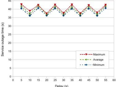
The results can be found in Fig. 3. They justify hypothesis 3: the average service outage times are approximately 5 seconds higher than the time that was left from the Dead Interval of OSPF at the time of stopping R2. (The stream was
restored because OSPF calculated a new route that did not contain the R2 router.)
Fig. 2. Service outage times in the function of the delay from the last
C-RP-Adv Message to the stopping of the R2 router
C. Limiting the service outage time by parameter tuning
As we have shown in section B, if the service outage was caused by the complete failure of a multicast router2 which is
an element of the path from the DR of the server to the DR of the client then the service outage time was determined by the parameters of the underlying unicast routing protocol. In our experiments, the service outage time was upper bounded by the
Dead Interval of OSPF. The actual value of the service outage
time depended on the elapsed time from the last OSPF Hello
message at the time of the failure of R2.
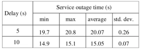
Hypothesis 4: The service outage time caused by the
complete failure of a multicast router can be limited by an appropriate setting of the OSPF Dead Interval parameter. The
measurements were taken in the usual way but using 20 seconds and 15 seconds as OSPF Dead Interval and Hello Interval, respectively. The used values of the delay from the
last OSPF Hello message to the failure of R2 were 5 and 10
seconds. The results can be found in Table 1. They justify hypothesis 4.
Fig. 3. Service outage times in the function of the delay from the last
OSPF Hello Message to the stopping of the R2 router
TABLE I. SERVICE OUTAGE TIMES IN THE FUNCTION OF THE DELAY
FROM THE LAST OSPF HELLO MESSAGETO THE STOPPING OF XORPON
XORP2ROUTER USING 20 SECONDS OSPF DEAD INTERVAL
Delay (s) Service outage time (s) min max average std. dev.
5 19.7 20.8 20.07 0.26
10 14.9 15.1 15.05 0.07
The significance of the findings of hypotheses 4 is that the time of the service outage caused by the complete failure of a multicast router can be limited by the appropriate choice of the
Dead Interval parameter of OSPF. Note that the service outage time cannot be arbitrarily decreased in this way for at least two reasons:
1) The choice of the Dead Interval parameter of OSPF has a consequence on the frequency of the OSPF Hello messages. This frequency should not be too high as these messages consume both network and router capacity.
2) The exchange of the topology information and the recreation of the routing tables in OSPF require a certain amount of time. Though this time was negligible in our experiments due to the small size of our test network, the situation can be different in the case of a real life multicast network for IPTV.
V. FUTURE RESEARCH AND RELATED WORK It is also our aim with the experiments described above to collect both measurement data and experience with PIM-SM implementations to be able to prepare a new or to improve an existing PIM-SM simulation model. Simulation is a powerful tool for the performance and fault tolerance analysis of complex ICT (Information and Communication Technology) systems [14]; and our measurement results may help in building a good simulation model.
Our preferred simulation environment is the OMNeT++ [15] discrete event simulation framework for multiple reasons:
it is modular, extensible and convenient it is open source and free for academic purposes we had good experiences with it in our previous
research projects [16] and [17].
The first PIM-SM model for OMNeT++ was published in [18]. The implementation was the MSc final project work of Juan Ángel Cachinero in 2009. His teacher, Raquel Perez Leal was kind enough to collect and send us the source code in 2013, however it turned out that the code was developed under a very old version (3.3) of OMNeT++ thus we abandoned it.
PIM-DM has been recently implemented for OMNeT++ at the Faculty of Information Technologies, Brno University of Technology as a part of the ANSA project and the implementation of PIM-SM is on the way according to [19]. We plan to join to this effort and complete the PIM-SM model with the implementation of its fault tolerance mechanism.
Multipath stream transmission [20] is also a novel and challenging idea. The MPT [21] library was developed and it is being actively researched at the Faculty of Informatics, University of Debrecen, see also [22] and [23]. We have already contacted Béla Almási, the first author of these papers and we are looking for a common ground for our research activities.
VI. CONCLUSIONS
We have given an introduction to the PIM-SM multicast routing protocol and the description of our test environment.
We have shown that RP is no more used at the end of phase two of PIM-SM thus its failure does not interrupt the ongoing media streaming. This is an important difference between the behaviour of the XORP and of the Cisco PIM-SM implementa-tions in phase 2.
We have shown that the complete failure of a PIM-SM router that resides in the media forwarding path results in service outage but the restoration of the stream does not requires an active RP rather it is done by the underlying unicast routing protocol (actually OSPF). The length of the service outage depends on the parameters of the underlying OSPF and can be bounded by the appropriate choice of the Dead Interval
parameter of OSPF.
Our results may be used by IPTV service providers for improving the availability and fault tolerance of their IPTV systems.
We plan to use our experience with the different PIM-SM implementations in the development and/or improvement of simulation models for PIM-SM.
ACKNOWLEDGMENT
The text and measurement methods of our previous paper [5] (about our experiments under the XORP platform) were reused in this paper but now our experiments were performed in the GNS3 environment.
REFERENCES
[1] S. Deering, D. Estrin, D. Farinacci, V. Jacobson, C. Liu, L. Wei, “The
PIM architecture for wide-area multicast routing”, IEEE/ACM
Transactions on Networking, Vol. 4, No. 2, pp. 153-162. April 1996. DOI:10.1.1.39.7251
[2] M. Sola, M. Ohta and T. Maeno: “Scalability of internet multicast protocols”, in: Proc. of INET'98, Geneva, Switzerland, July 1998.
[3] Silvano Da Ros, Content Networking Fundamentals, Cisco Press, 2006, ISBN: 1-58705-240-7
[4] G. Lencse and I. Derka, “Towards the modelling of the fault tolerance mechanism of the PIM-SM multicast routing protocol in an IPTV
Environment” Proceedings of the 2012 European Simulation and Modelling Conference (ESM'2012): Modelling and Simulation 2012, (Essen, Germany, 2012. Oct. 22-24.) EUROSIS-ETI, 152-156. [5] G. Lencse and I. Derka, “Investigation of the fault tolerance of the
PIM-SM IP multicast routing protocol for IPTV purposes”, Infocommunica-tions Journal, Vol. V, No. 1. (March, 2013) pp. 21-28.
[6] XORP Inc. and individual contributors, XORP user manual, Version 1.8-CT, 2010.
[7] Graphical Network Simulator – GNS3 http://www.gns3.net/
[9] B. Fenner, M. Handley, H. Holbrook, and I. Kouvelas, “Protocol
Independent Multicast - Sparse Mode (PIM-SM): Protocol Specification
(Revised)”, IETF, August 2006, RFC 4601
[10] N. Bhaskar, A. Gall, J. Lingard, and S. Venaas, “Bootstrap Router (BSR) Mechanism for Protocol Independent Multicast (PIM)”, IETF,
January 2008, RFC 5059
[11] G. Malkin, “RIP Version 2”, IETF, November 1998, RFC 2453
[12] J. Moy, “OSPF Version 2”, IETF, April 1998, RFC 2328
[13] Digital Video Broadcasting (DVB); Transport of MPEG-2 TS Based DVB Services over IP Based Networks, ETSI TS 102 034 V1.4.1 (2009-08)
[14] L. Muka and G. Muka. “Creating and using key network-performance indicators to support the design and change of enterprise infocommunication infrastucture”, Proceedings of 2012 International
Symposium on Performance Evaluation of Computer and Telecommunication Systems (SPECTS 2012), (Genoa, Italy, July 8-11, 2012) Volume 44, Books 12, pp. 737-742.
[15] A. Varga and R. Hornig, “An overview of the OMNeT++ simulation
environment”, Simutools '08: Proceedings of the 1st international conference on Simulation tools and techniques for communications, networks and systems & workshops (Marseille, France, March 7, 2008), ICST, http://dl.acm.org/citation.cfm?id=1416290
[16] G. Lencse I. Derka and L. Muka, “Towards the efficient simulation of telecommunication systems in heterogeneous execution environments”, Proc. of the 36th International Conference on Telecommunications and Signal Processing (TSP 2013), (Rome, Italy, July 2-4, 2013), pp 304-310. http://ieeexplore.ieee.org/xpl/freeabs_all.jsp?arnumber=6613941
[17] G. Lencse and I. Derka, “Testing the speed-up of parallel discrete event
simulation in heterogeneous execution environments”, Proceedings of the ISC'2013, 11th Annual Industrial Simulation Conference, (Ghent, Belgium, May 22-24, 2013) EUROSIS-ETI, 101-107.
[18] R. P. Leal, J. Á. Cachinero, E. P. Martín, “New approach to inter
-domain multicast protocol”, ETRI Journal, Vol 33. No. 3. June 2011, pp.
355-365. http://dx.doi.org/10.4218/etrij.11.0110.0405
[19] V. Veselý, O. Ryšavý, M Švéda, “IPv6 unicast and IPv4 multicast routing in OMNeT++”, Simutools '13: Proceedings of the 6th International ICST Conference on Simulation Tools and Techniques, (Cannes, France, March 5-7, 2013) pp. 346-349. http://dl.acm.org/citation.cfm?id=2512785
[20] B. Almási, Sz. Szilágyi, “Multipath ftp and stream transmission analysis using the MPT software environment”, International Journal of
Advanced Research in Computer and Communication Engineering, Vol. 2, Issue 11, (November 2013) pp. 4267-4272.
[21] B. Almási, A. Harman, “An overview of the multipath communication technologies”, Proceedings of the Conference on Advances in Wireless
Sensor Networks 2013 (AWSN 2013), Debrecen University Press, Debrecen, Hungary, ISBN: 978-963-318-356-4, 2013, pp. 7-11. [22] B. Almási, Sz. Szilágyi, "Throughput Performance Analysis of the
Multipath Communication Library MPT", Proceedings of the 36th International Conference on Telecommunications and Signal Processing (TSP 2013), (Rome, Italy, July 2-4, 2013), pp 86-90.
[23] B. Almási, “Multipath Communication – a new basis for the Future
Internet Cognitive Infocommunication”, Proceedings of the
CogInfoCom 2013 Conference, (Budapest, Hungary, December 2-5, 2013), pp. 201-204.
APPENDIX
This script was used for testing our second hypothesis in section 4.B. The scripts used for the other tests are very similar to this one.
#!/bin/bash
rtlog="/mnt/data/measurements/runtime.log" for j in {1..11}
do
echo -e "$j-th run\t$(date +%T.%N | cut -b1-12)" >> $rtlog
echo -e "================================================" >> $rtlog mkdir /mnt/data/capture/t$j >> $rtlog 2>&1
for i in {5..55..5} do
echo -e "\nDelay $i seconds\t$(date +%T.%N | cut -b1-12)" >> $rtlog echo -e "---" >> $rtlog
msglog="/mnt/data/measurements/messages_$j-$i.log" echo -e "R2 start\t$(date +%T.%N | cut -b1-12)" >> $rtlog
sshpass -p cisco ssh -t admin@r2 "tclsh disk0:switchon.cfg" >> $msglog 2>&1
ospf=$(sshpass -p cisco ssh -t admin@r2 "sh ip route ospf" 2>/dev/null | wc -l | tr -cd "[:print:]") echo -e "Number of OSPF routes: $ospf\t$(date +%T.%N | cut -b1-12)" >> $rtlog
while [ $ospf -eq 0 ] do
ospf=$(sshpass -p cisco ssh -t admin@r2 "sh ip route ospf" 2>/dev/null | wc -l | tr -cd "[:print:]") done
echo -e " Number of OSPF routes: $ospf\t$(date +%T.%N | cut -b1-12)" >> $rtlog echo -e "R2 started\t$(date +%T.%N | cut -b1-12)" >> $rtlog
echo -e "Sending the stream\t$(date +%T.%N | cut -b1-12)" >> $rtlog
screen -S streaming -d -m ssh -t steve@server "/home/steve/streaming.sh" >> $msglog 2>&1 echo -e "Receiving the stream \t$(date +%T.%N | cut -b1-12)" >> $rtlog
screen -S streamplay -d -m ssh -t steve@client "/home/steve/streamplay.sh" >> $msglog 2>&1
rp=$(sshpass -p cisco ssh -t admin@r2 "show ip pim rp" 2>/dev/null | awk '{ print $4 }' | sed 's/,//' | \ tr -cd "[:print:]")
echo -e "Current RP: $rp\t" >> $rtlog
echo -e "Waiting until the restoration of RP\t$(date +%T.%N | cut -b1-12)" >> $rtlog while [ "$rp" != "192.168.2.1" ]
do
rp=$(sshpass -p cisco ssh -t admin@r2 "show ip pim rp" 2>/dev/null | awk '{ print $4 }' | sed 's/,//' | \ tr -cd "[:print:]")
done
echo -e "RP was restored\t$(date +%T.%N | cut -b1-12)\tRP: $rp" >> $rtlog
tshark -i eth2 'ip host 192.168.16.1 and pim[0]=0x28' -c 1 -t a >> $msglog 2>&1 echo -e "Cand-RP-Advertisement was found\t$(date +%T.%N | cut -b1-12)" >> $rtlog echo -e "Start Capture\t$(date +%T.%N | cut -b1-12)" >> $rtlog
screen -S capture -d -m tshark -i eth3 -a duration:180 -s 128 -w /mnt/data/capture/t$j/test-$i.pcap >> \ $msglog 2>&1
echo -e "Delaying $i seconds\t$(date +%T.%N | cut -b1-12)" >> $rtlog sleep $i >> $msglog 2>&1
echo -e "Elapsed\t$(date +%T.%N | cut -b1-12)" >> $rtlog echo -e "Set Marker\t$(date +%T.%N | cut -b1-12)" >> $rtlog ping -c 1 client >> $msglog 2>&1
echo -e "Stop R2 \t$(date +%T.%N | cut -b1-12)" >> $rtlog
sshpass -p cisco ssh -t admin@r2 "tclsh disk0:switchoff.cfg" >> $msglog 2>&1
echo -e "Wait until the end of the capture interval\t$(date +%T.%N | cut -b1-12)" >> $rtlog capture=$(ps aux | grep tshark | wc -l)
while [ $capture -gt 1 ] do
capture=$(ps aux | grep tshark | wc -l) done
echo -e "Stop receiving the Stream\t$(date +%T.%N | cut -b1-12)" >> $rtlog screen -S streamplay -X quit >> $msglog 2>&1
screen -S streaming -X quit >> $msglog 2>&1
echo -e "End of Capture\t$(date +%T.%N | cut -b1-12)\n" >> $rtlog done