ABSTRACT: The present work addresses a sensitivity analysis investigation of the aeroelastic stability margins for the VSB-30 sounding rocket during the atmospheric light phase. Parametric stability analyses are performed considering variations of the inertia properties of the modular payload. Such variations can be caused by different type and/or number of experiments (payload modules). The aerodynamic model is based on a supersonic unsteady potential aerodynamic method. Freestream conditions depend on the light speed and atmosphere. An equivalent structural dynamic model of the rocket is represented by a beam-like structure. The objective of this investigation is to establish an aeroelastic model for aeroelastic stability and response analyses, as well as a procedure for the identiication of stability margins for rockets. The resulting aeroelastic model should be further used in MDO processes for the improvement of the vehicle light performance. The results of the present effort indicate that the lutter behavior of the VSB-30 sounding rocket is suficiently robust inside the operational envelope, even considering the environmental and loading conditions. The spinning effect, in this case, does not play a signiicant role, because the lutter margins remain almost unaltered with and without VSB-30 body spin.
KEYWORDS: Sounding rockets, Aeroelastic analysis, Flutter margins, Sensitivity studies.
A Sensitivity Investigation on the Aeroelastic
Dynamic Stability of Slender Spinning
Sounding Rockets
Roberto Gil Annes da Silva1, José Guido Damilano1, João Luiz F. Azevedo1
INTRODUCTION
European research on microgravity required a new sounding rocket with performance similar to the one delivered by the English rocket Skylark-7, whose production had been discontinued. Instituto de Aeronáutica e Espaço (IAE), in Brazil, took on the task of the rocket development and complete integration in a joint efort with the Deutsches Zentrum für Lut und Raumfahrt (DLR), responsible for the payload of microgravity experiments. Several modiications were performed on the previously developed VS-30 sounding rocket, in order to satisfy the required speciications for new scientiic and technological experiments in the microgravity environment. he resulting modiied vehicle, named VSB-30, is a two-stage spinning-stabilized slender sounding rocket, with two sets of three ins on each stage, whose engines use a solid propellant (Duarte et al., 2005).
he VSB-30 rocket light operation is divided into two phases: the irst stage light (FSF) and the second stage light (SSF). he engines accelerate the vehicle to a ballistic light path towards the desired microgravity condition. A more recent application of the baseline VSB-30 sounding rocket coniguration regards in-light experiments on the aerodynamic behavior and thermal problems of an unconventional asymmetric shape for reentry vehicles comprising multifaceted surfaces with sharp edges (SHEFEX) (Turner et al., 2006). he aim of the experiment was
to correlate numerical analysis results with actual light data regarding the aerodynamic efects and structural concept for the thermal protection system. Hence, the development of an aeroelastic model of the VSB-30 vehicle should be very useful
1.Instituto de Aeronáutica e Espaço – São José dos Campos/SP – Brazil
Author for correspondence: João Luiz F. Azevedo | Praça Marechal Eduardo Gomes, 50 – Vila das Acácias | CEP 12228-903 São José dos Campos/SP – Brazil |
for the aeroelastic stability and response investigation for any type of proposed conigurations, including SHEFEX.
Typically, slender-body inned vehicles can present two types of lutter mechanisms, i.e., in bending-torsion lutter
and body pitch-bending lutter (Martin, 1958). Examples of rocket lutter analysis have been well documented in several reports and articles (Azevedo, 1988; Bae et al., 2004; Francesco
Capri et al., 2006; Garcia-Fogeda and Liu, 1988; McNamara
and Friedmann, 2006; Paek et al., 2002). Some of them
concern in lutter, for example, when the rocket presents deployable ins. Nonlinear phenomena, such as free-play, also lead to nonlinear aeroelastic behavior (Bae et al., 2004).
In the literature, several eforts have been well documented (Chae, 2004; Chae and Hodges, 2003; Haddadpour, 2006; Heddadj and Cayzac, 2000; Livshits et al.,
1996; Meyers, 1973; Murphy and Mermagen, 2001; Murphy and Mermagen, 2005; Platus, 1992), regarding the investigation of the light dynamic/aeroelastic response behavior of free light spinning (or not) rockets and missiles. Moreover, in some studies the coupling between light mechanics, aeroelasticity, and control system (aeroservoelastic coupling) has been investigated (Haddadpour, 2006). Motivations for these studies are usually associated to the fact that light vehicles with slender conigurations might experience aeroelastic instability during light due to coupling between a short period rigid-body mode and a body-bending mode. Such a coupling might afect the planned trajectory of the vehicle and, in the case of military rockets, the weapon aiming system could be compromised.
Most of the previously cited investigations employ slender body theory for the aerodynamic model of the elastic body, combined with a quasi-steady aerodynamic model representing the body global aerodynamic coeicients. However, for the best assessment of aeroelastic instabilities, a more accurate prediction method to compute the unsteady aerodynamics was presented by Garcia-Fogeda and Liu (1988), the so-called Harmonic Potential Panel (HPP) method. Further development on more accurate methods, based on liting surface theory, for the prediction of unsteady airloads aeroelastic to analyze supersonic wing-body conigurations were presented by Chen and Liu (1990), and Liu et al. (1997), which is, in fact, a uniied
hypersonic-supersonic liting surface method.
Nevertheless, liting surface methods are limited to linear computation of the unsteady airloads. For this reason,
computational luid dynamics for unsteady aerodynamic modeling of transonic airloads has also been used for transonic aeroelastic analysis of body alone rockets (Azevedo, 1988) and wing-body-like vehicles (Francesco Capri et al., 2006).
A review of the state-of-the-art on advanced methods for computational luid dynamics and heat transfer applications of hypersonic aeroelasticity and aerothermoelasticity is presented by MacNamara and Friedmann (2006).
he scope of the present investigation is the study of the aeroelastic stability (lutter) of a free light spinning rocket. he strategy for the parametric investigation regarding a sensitivity analysis should be based on the identiication of the lutter margins as a function of the variation of the inertial properties of the payload, solid propellant consumption, as well as the light environmental conditions. A set of adequate steps for an aeroelastic investigation of sounding rockets is proposed. he procedure for the analysis, as well as the assumed hypotheses, should be mainly based on the light dynamic behavior of the vehicle during its operation. It is important to note that diferently from conventional aircrat, the rocket atmospheric light does not present a steady behavior as in a cruise condition. he vehicle should be subjected to strong environmental variations associated to its light level, low speed and its inertial characteristics.
MATHEMATICAL MODELS
Structural Dynamic Model
he VSB-30 airframe is represented by a inite element structural dynamic reduced order model, composed by beam and plate elements connected by nodes to represent the body, the in spars and the in surfaces, respectively. Such an approach is suicient for the aeroelastic stability analysis of the vehicle. In the vehicle body nodes, the distribution of inertial characteristics is approximated by lumped masses representing the inertia properties. A sketch of the inite element model, including the distributed masses, will be presented in the forthcoming paragraphs. Since the rocket engines burn the solid propellant, a considerable rate of change in mass should be considered in the modeling of the vehicle structure. hus, mass properties represented in the structural dynamic model, for each light condition, change as a function of time.
model was developed with the MSC/NASTRAN®
sotware (MSC/NASTRAN, 1995) to compute the natural frequencies and mode shapes for the analysis, assuming a piecewise linear model, because the mass variation should be assumed as constant at a given instant.
he stability of the VSB-30 rocket is guaranteed by the ins and the induced spin ater litof. herefore, it would be desirable to include spinning efects in the structural dynamic modeling. Spinning efects can lead to changes on mode shapes and natural frequencies of structures. Paek et al. (2002) presented
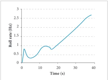
results on the investigation of wraparound inned projectiles lutter. Results of their aeroelastic analysis indicate that lutter speeds depend on the roll rate. Furthermore, in that special case, there was a signiicant deformation of the wrapped in with the increase of the roll rate. For their analysis the order of the roll rate was about three times the irst natural frequency of the body and ten times smaller than the irst natural frequency of the in (1st in bending). So, it was possible to conclude that the spinning efects had to be taken into account for the identiication of the rocket mode shapes and natural frequencies.
Figure 1 presents the roll rate for the VSB-30 vehicle until 40 seconds of light. It is observed that the rolling frequencies are moderately low. herefore, such an efect will not be considered in the VSB-30 rocket analysis because the spinning rates are between four to six times smaller than the irst mode shape of the vehicle (body 1st bending), thus not inducing signiicant changes in stifness nor in gyroscopic efects.
On the other hand, even in this case, an investigation on the spinning efects was performed, supposing that this
aeroelastic analysis methodology could be applicable to other classes of sounding rockets. From the dynamics rotating system, it is desirable to consider spinning efects, which might include the Coriolis and centrifugal efects by introducing the gyroscopic damping matrix into the dynamic equations, as well as the diferential stifness due to nonlinear efects (Heddadj and Cayzac, 2000). hese efects are signiicant when the spinning roll rates are larger than the current ones (Fig. 1). he inclusion of such efects may lead to structural dynamic changes that might inluence the lutter mechanisms of the airframe. A MSC/NASTRAN DMAP option was used to compute the modal characteristics of the rotating vehicle, and the corresponding theory is well documented in MSC/NASTRAN V70 (1995).
Unsteady Aerodynamic Model
In the present investigation, only aeroelastic analyses at supersonic low conditions will be performed. he aerodynamic modeling method of unsteady linear potential lows is based on the discrete kernel function approach. he development of discrete element kernel function methods is based on integral solutions of the small disturbances linearized potential low equation. In this work, the ZONA7U
method (ZAERO, 2003), implemented in the ZAERO®
sotware system, has been used to model the unsteady airloads for lutter analysis (Liu et al., 1997). Chen and Liu
(1990) present the mathematical formulation of the ZONA7 method for supersonic aerodynamic modeling of wing body conigurations. Its extension, which accounts for the liting surface thickness efects, is named ZONA7U method (Liu et al., 1997), and is also implemented in the ZAERO®
sotware package.
The ZONA7U method is different from ZONA7 due to the inclusion, in the former, of the thickness effect correction. Thickness corrections are an important issue to be considered, leading to the improvement of the flutter speed prediction (Liu et al., 1997). In most cases,
the flutter speed decreases when the fin thickness is considered (Liu et al., 1997).
Special care should be taken during the meshing process. For example, depending on the Mach number, the liting surface elements (panels) should have an adequate aspect ratio for the computation of supersonic lows. Another important issue to be considered is the need for a mesh convergence study based on the resulting lutter speed dispersion.
Roll rate (Hz)
0 1 2 3
0.5 1.5 2.5
Time (s)
0 10 20 30 40
Such study might be seen as a tool to identify the best cost-beneit relation regarding the size of the aerodynamic mesh for modeling the body and liting surfaces unsteady aerodynamics.
AEROELASTIC MODELING
he scope of the aeroelastic analysis to be presented here is the lutter investigation of a spinning sounding rocket based on the unsteady aerodynamic model of the full vehicle. It is usual to investigate rocket in lutter by just modeling the isolated in (Bae et al., 2004; Paek et al., 2002). However,
possible interference efects could inluence the unsteady aerodynamic behavior of the vehicle, and, for this reason, the full vehicle should be modeled. he structural dynamic behavior is also assumed as linear, and the spinning efect is neglected for the aforementioned reasons.
It is supposed, as a irst approach, that the present aeroelastic model is linear regarding the aerodynamic and structural models. he scope here is the investigation of the vehicle lutter mechanisms. Small aeroelastic displacements are assumed and the development of this baseline aeroelastic model will be important for further studies on Multidisciplinary Design and Optimization (MDO) applied to the vehicle design and upgrade processes. Also, this baseline linear model should be important for future development on computational aeroelasticity applied to transonic aeroelastic stability and response, assuming nonlinear aerodynamic models for correction of the linear aerodynamic methods (ZAERO, 2003).
Description of the Vehicle
he VSB-30 sounding rocket is composed of two tandem rocket engines. Its total length is 12.699 m and it has a total mass of about 2,200 kg at litof. Evidently, this may vary depending
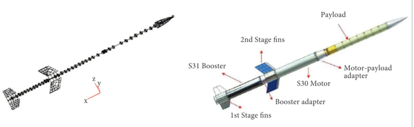
on the payload coniguration. In the present study, only the aeroelastic analysis of the VSB-30 sounding rocket assembled with modular cylindrical payload modules is investigated. hese modular payloads are assembled in tandem as a set of two, three or four modules. hey are mass balanced in relation to the vehicles longitudinal axis (assumed here as the “x” axis). Figure 2 presents the vehicle inite element structural model and the corresponding CAD drawing.
Basic Hypotheses and Assumptions
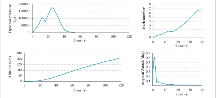
he VSB-30 vehicle is a ballistic sounding rocket whose light altitude range from sea level is 250 km. Its light path is designed in order to achieve suicient time in microgravity conditions for scientiic and technological experiments. he vehicle reentry light phase is not included in the scope of the present investigation. Figure 3 shows the typical altitude, Mach number, dynamic pressure and angle of attack for this class of vehicles as a function of time. he data shown represent the case for which the vehicle comprises four payload modules for scientiic experiments.
Information presented in Fig. 3 allows the formulation of hypotheses and conditions to set the aeroelastic analysis procedure. One should observe that the Mach number varies up to the hypersonic low condition, remaining constant aterwards. However, while the vehicle lies within the atmosphere, the maximum Mach number is supersonic (3.313) at the maximum dynamic pressure, which can be obtained from the corresponding chart in Fig. 3.
In fact, one can observe that there are two dynamic pressure peaks. Furthermore, each of these peaks is associated with the vehicle coniguration in each stage: in the irst stage, when the vehicle remains with two tandem rocket engines
Payload
Motor-payload adapter
1st Stage fins 2nd Stage fins
Booster adapter S30 Motor S31 Booster
z
x y
and two set of ins, and, in the second stage, in which the vehicle is composed by a single rocket engine and a single set of ins. his is the reason why the aeroelastic analysis procedure should be divided into irst and second stage light analyses. Since the stages separate, it will be necessary to consider two distinct dynamic models of the airframe, one before separation and another ater separation.
In the case of a non matched-point lutter analysis, parametric variations around the maximum dynamic pressure condition are assumed. hese parametric variations should be set as freestream speed and Mach number, light altitude and mass variations regarding the solid propellant consumption and number of payload modules. his irst approach for the aeroelastic analysis provides the sensitivity of the aeroelastic stability due to payload and solid propellant variations.
he spinning behavior of the vehicle is associated with the body roll rate. he spin may promote Coriolis and Magnus efects. Such efects could have an important inluence on the light dynamic behavior of the vehicle. he idea of inducing a spin during light is related to improving the light dynamic longitudinal stability margins of the vehicle. he reader should keep in mind that a sounding rocket is essentially a ballistic body, that is, there are no controls acting during its light path.
Coriolis efects are associated to gyroscopic forces which result from the spin. For this reason, the structural dynamic behavior of the vehicle should be altered by the appearance of a gyroscopic damping matrix and a diferential stifness due
to centrifugal forces (Francesco Capri et al., 2006). However,
this type of efect can be negligible when the vehicle roll rates are small. For the present investigation, it is assumed that roll rates of 1.42 Hz and 0.91 Hz at the irst and second stages, respectively, are suiciently small and can be neglected, since they are not able to promote signiicant changes in the structural dynamic behavior of the vehicle.
Another efect associated to a spinning body is the Magnus efect. his type of efect is represented by a lit force induced by the rotating body in angle of attack. his efect changes the mean low around the vehicle, and it is signiicant when the angle of attack is high. hus, the small disturbance low should not be altered by the loading changes around a mean steady low condition. Furthermore, from the corresponding chart in Fig. 3, it is possible to observe that the angle of attack is suiciently small throughout the light path, resulting in negligible Magnus efect.
Structural Dynamic Model
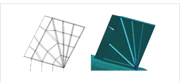
he VSB-30 rocket is represented by a beam-like equivalent structure, suiciently accurate to capture the global mode shapes of the airframe. Moreover, the ittings are represented by a set of constraints which might represent the physical coupling between the parts of the vehicle. he ins are represented by a combination of beams and plate elements, as in the real structure. he second stage engine in internal structure resembles a “spider web” beam structure, as observed in Fig. 4.
Dynamic pressure
(pa)
Altitude (km)
Mach number
Angle of Attack (deg)
0
0
0 0.1 0.2 0.3 0.4 0.5 0.6 0.7 1 2 3 4 5 6 7 8
0
40 80 120 160 200
200000
150000
100000
50000
Time (s)
Time (s)
Time (s) Time (s) 0
0 10 20
20 30 40
40
0 10 20 30 40 60 80 100 120
0 20 40 60 80 100 120
he mass of the solid propellant is distributed in several points along the vehicle longitudinal axis, and its consumption is represented by subtracting their corresponding value, as the propellant is burned, for each instant of analysis.
Aerodynamic Model
he aerodynamic model is developed using the ZAERO sotware (Chen, 1999). A body of revolution subdivided into panels was assumed to represent the aerodynamic shape of the vehicle. For the ins, a lat plate aerodynamic representation is assumed, including the thickness correction (ZAERO, 2003). he correction for thickness efects is important for Mach numbers higher than 1.2. he reader should remember that the aeroelastic stability behavior is less conservative when this correction is not considered (ZAERO, 2003).
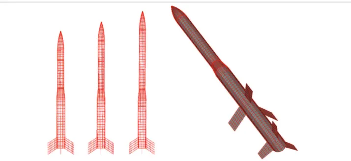
Figure 5 shows the aerodynamic meshes used for the present investigation. Each payload coniguration is represented by a proper aerodynamic mesh. Furthermore, for the irst stage light phase, the aerodynamic model represents the whole
vehicle including the two sets of ins. he chosen Mach numbers for the stability investigation are the corresponding values at maximum dynamic pressure conditions. Table 1 shows the main light parameters for each coniguration and light phases.
he maximum dynamic pressure identiied during the light of the irst stage occurs when the light altitude is around 3,400 m, at Mach number 1.6, that is, 12.5 seconds ater litof, for the case of the vehicle conigured with two payload modules. hese conditions are taken as reference to perform the aeroelastic stability analyses. hey are diferent from other conigurations of the vehicle, since they also depend on the number of payload modules. It is assumed that the Mach number and light altitude, for the reference conditions, are constant, but the freestream speed varies around the speciied Mach number. Table 1 shows the light parameters for each of the conigurations analyzed, as well as the ight phases represented as “irst” and “second” stages.
he number of panels, used in the aerodynamic mesh for the body, depends on the coniguration to be
Figure 4. Finite element model of the “spider web” like structure of the second stage ins.
Table 1. Reference conditions for the aeroelastic stability analyses.
Coniguration Time (s) Dyn. Pressure (Pa) Mach number Altitude (m)
light phase 1st stage 2nd stage 1st stage 2nd stage 1st stage 2nd stage 1st stage 2nd stage
2 modules 12.5 24.2 117420.0 179525.5 1.599 3.375 3518 11050
3 modules 12.5 24.5 112684.4 175899.4 1.558 3.337 3434 11037
analyzed. However, the number of panels, used to mesh the ins, remains constant since these structures do not change according to the conigurations to be analyzed. he remaining task to proceed in the lutter analysis is a mesh convergence study to evaluate the robustness of the aerodynamic model for stability investigations. he idea is to identify which are the lutter modes and to proceed with the mesh reinement only in the parts of the vehicle in which modal displacements contribute for the lutter mode. Such investigations will be discussed further, as soon as the lutter mechanisms are identiied.
FLUTTER ANALYSIS RESULTS
he aeroelastic analysis procedure is based on the investigation of the aeroelastic stability within the vehicle light envelope. he strategy adopted here is to observe the dynamic pressure-time history, demonstrated in Fig. 6. In this igure, the red line indicates that the points below it may not be included in the aeroelastic analysis procedure. his is because this decrement in the dynamic pressure does not ofer any risk in terms of lutter, since larger dynamic pressures are reached before, as shown in Fig. 6.
he non-matched point lutter analysis will be based on the variation of the freestream speed at each of the maximum dynamic pressure peaks, each one associated to the irst and second stage light phases. his is not the best approach for lutter substantiation since only a single eigenvalue will
Figure 5. Aerodynamic meshes for the VSB-30 rocket for two stages coniguration and four modules (right), and the single second stage for 2 to 4 modules (left).
Dyn. Press (Pa)
0 180000 200000
160000 140000 120000 100000 80000 60000 40000 20000
Time (s)
0 5 10 15 20 25 30 35 40
Figure 6. Typical dynamic pressure-time history.
represent the true aerodynamic damping (Chen, 1999) and the associated aeroelastic frequency. Nevertheless, this approach is fast enough to qualitatively identify the flutter mechanism to be explored on a subsequent matched-point flutter analysis. The reference Mach number and density are the same values identified at the maximum dynamic pressure condition.
he resulting lutter mechanism identiied by the non-matched point lutter analysis is represented by the coupling of the 7th and 9th anti-symmetric modes. hese modes are the second stage in bending and torsion modes, which are illustrated in Fig. 7.
structural dynamic behavior. he lutter mechanism could be anticipated or delayed, depending on the coalescent modes. For this reason, further investigation is recommended in order to introduce the spinning efect in the vehicle dynamic model, due to the inluence of the gyroscopic efects produced by the spin.
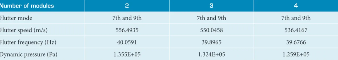
he results of the sensitivity investigation based on the number of payload modules are summarized in Table 2.
he reader may observe that the computed lutter speeds associated with the number of modules are related to the same lutter mechanism, and the lutter speed reduction is less that 4%. his fact is a good indication that the vehicle is suiciently robust in terms of the variations of payload mass regarding the aeroelastic stability. Moreover, this result makes sense because the lutter mode results from a coalescence of two anti-symmetric in mode shapes. hat is, the dynamic contributions of the vehicle body modes do not play an important role in the lutter mechanism.
From the discussion above, it is possible to conclude that this change in lutter speed should be mostly related to the vehicle environmental conditions, since the dynamic pressure for each of the conigurations is diferent. Figure 8 shows a comparison between the dynamic pressures at the same time frame for two, three and four payload modules.
he most critical conigurations occur when the vehicle lies with two payload modules. Such coniguration, during the atmospheric light phase, subjects the vehicle to dynamic pressures higher than the others do.
he next step in the study was an analysis still based on a non-matched point lutter solution. However, unlike the previous procedure, this one was repeated for diferent Mach numbers, each of which associated to a diferent light condition. In this case for the unsteady aerodynamic model used to compute the lutter condition, these reference Mach numbers are used to
Table 2. Flutter speeds and dynamic pressure for the VSB-30 vehicle in the irst stage of light – non-matched point lutter analysis.
Number of modules 2 3 4
Flutter mode 7th and 9th 7th and 9th 7th and 9th
Flutter speed (m/s) 556.4935 550.0458 536.4167
Flutter frequency (Hz) 40.0591 39.8965 39.6766
Dynamic pressure (Pa) 1.355E+05 1.324E+05 1.259E+05
Figure 8. Comparison of the dynamic pressure time history for two, three and four payload modules.
Dyn. Press (Pa)
0 180000 200000
160000 140000 120000 100000 80000 60000 40000 20000
Time (s)
0 10 20 30 40 50
2 modules
3 modules
4 modules
Figure 7. Flutter mechanism in the irst stage light phase.
7th mode (37.2 Hz)
9th mode (66.9 Hz)
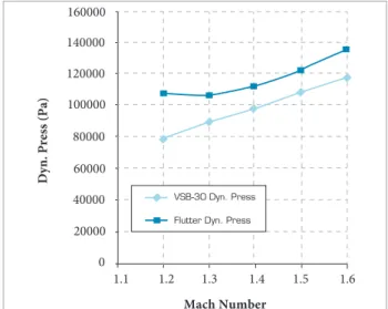
generate the aerodynamic inluence coeicients. Figure 9 shows the computed lutter dynamic pressures, when the vehicle is conigured with two payload modules.
he results represented in Fig. 9 indicate that lutter dynamic pressures are above the dynamic pressure imposed on the vehicle during actual light. It is possible to conclude, based on the studied trajectories, that increasing the number of payload modules reduces the chance for lutter, because the higher vehicle masses will decrease the light speeds in lower altitudes.
In the second stage light, environmental conditions are more favorable because the higher altitudes lead to lower densities and dynamic pressures. On the other hand, light speeds are higher, approaching two times the Mach number of the irst stage light. For this analysis, the mass ratio concept is introduced to help understand why at higher dynamic pressures the same airframe remains stable in terms of lutter, as demonstrated in Table 3.
A lower mass ratio leads to a lower amount of energy needed to promote the coalescence of aeroelastic modes which may lead to lutter. On the other hand, there is a need for high kinetic energy low from which energy would be extracted to
cause lutter. Looking at Fig. 10, it is possible to understand why, at higher altitudes and Mach numbers, even though the dynamic pressure is high, the mass ratio is also high enough, thus retarding the coalescence of the modes for lutter. his explains why it should be necessary to concentrate eforts on analyzing lutter stability nearby transonic Mach numbers.
he matched-point lutter analysis considering the pair density (altitude)/Mach number is the subsequent step in the whole process. hus, the true aeroelastic damping curves, as functions of the freestream low conditions, are computed. his kind of analysis is more expensive, computationally speaking, since it is necessary to calculate an aerodynamic inluence coeicient matrix for each Mach number in- cluded in the proile to be investigated. Once these matrices are generated, it is possible to repeat the lutter computation for a set of Mach-altitude (density) pairs.
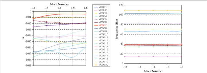
he results of the matched-point lutter analysis indicate that the vehicle is free from lutter mechanisms inside its light envelope. However, the critical coniguration, in terms of lutter, is the one in which the vehicle is conigured with two payload modules. Figure 11 shows that in the typical matched-point lutter analysis it is likely that the 7th mode is unstable, even though its corresponding natural frequency remains practically constant.
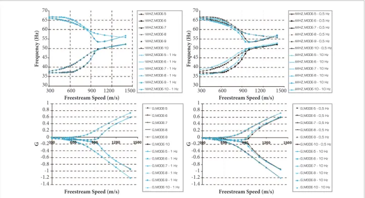
he inclusion of spinning efects considers the vehicle rotating between 0.5 Hz to 10 Hz. In the latter, the roll rates are beyond those at the maximum dynamic pressure condition during irst stage light. Here, the same conditions described above, i.e., vehicle with two payload modules, are investigated
regarding the sensitivity of the lutter dynamic pressures due to a projected increase in roll rates. Figure 12 shows the sensitivity of the lutter dynamic pressure as a function of the roll rate. his result indicates that increasing the roll rate leads to a decrease in the lutter dynamic pressures, in the case of the coupling of the 7th and 9th modes. he reader should remember that these results refer to a non-matched lutter point analysis.
Looking at Fig. 13, this behavior is clearly understood. Damping and frequency evolution, as the roll rates increase,
Figure 9. Flutter dynamic pressures for VSB-30 rocket, 1st stage light, two payload modules.
Dyn. Press (Pa)
0 160000
140000
120000
100000
80000
60000
40000
20000
Mach Number
1.1 1.2 1.3 1.4 1.5 1.6
VSB-30 Dyn. Press
Flutter Dyn. Press
Table 3. Flutter speeds and dynamic pressure for the VSB-30 vehicle during the second stage light.
Number of modules 2 3 4
Flutter mode 5th No lutter No lutter
Flutter speed (m/s) 1950.773 No lutter No lutter
Flutter frequency (Hz) 54.1746 No lutter No lutter
can be seen in the right side of Fig. 13. he coupling mechanism is altered in such a way that the lutter speed is lower with the increase of the roll rate. Such behavior occurs because the increase of the natural frequencies of the irst in anti-symmetric bending mode is mostly subjected to diferential stifness efects in relation to the irst in anti-symmetric torsion mode. hat is, the apparent increase in stifness of the in leads to an increase in the natural frequency. herefore, there is a contribution for the coupling between the bending and torsion modes, while the frequency remains almost unaltered.
Another interesting behavior to be noted concerns a second and third coupling between the 6th and 8th, and 5th and 10th modes, respectively. he coalescence of these modes leads to higher lutter speeds, which are, therefore, not taken into account in the present analysis. However, the reader should observe that the spinning efects for such couplings are more signiicant than
Figure 11. Matched point lutter analysis results for the two-module payload coniguration.
Mach Number
Mach Number
G Frequency (Hz)
40 60 80 120 20 100 -0.01 0
1.2 1.3 1.4 1.5 1.6
1.2 1.3 1.4 1.5 1.6
-0.02 -0.03 -0.04 -0.05 -0.06 -0.07 -0.08 -0.09 0 MODE-1 MODE-2 MODE-3 MODE-4 MODE-5 MODE-6 MODE-7 MODE-8 MODE-9 MODE-10 MODE-11 MODE-12 MODE-13 MODE-14 MODE-15 MODE-16 MODE-17 MODE-18 MODE-19 MODE-20 Mach Number Mach Number
G Frequency (Hz)
40 60 80 120 20 100 -0.01 0
1.2 1.3 1.4 1.5 1.6
1.2 1.3 1.4 1.5 1.6
-0.02 -0.03 -0.04 -0.05 -0.06 -0.07 -0.08 -0.09 0 MODE-1 MODE-2 MODE-3 MODE-4 MODE-5 MODE-6 MODE-7 MODE-8 MODE-9 MODE-10 MODE-11 MODE-12 MODE-13 MODE-14 MODE-15 MODE-16 MODE-17 MODE-18 MODE-19 MODE-20
Dyn. Press (KPa)
0 2 4 6 8 10
130 131 132 133 134 135 136 137 138 139 140
Roll rate (Hz)
With roll rate
W/O roll rate
Figure 12. Dynamic pressure as a function of the vehicle roll rate.
Figure 10. Mass ratio and Mach number as functions of the light altitude.
Mach Number 0 1 2 3 4 0.5 1.5 2.5 3.5 Altitude (km)
0 1 2 3 4 5 6 7 8 9 10 11
Mass Ratio 0 40 80 120 160 20 65 100 140 Altitude (km)
0 1 2 3 4 5 6 7 8 9 10 11
Mach Number 0 1 2 3 4 0.5 1.5 2.5 3.5 Altitude (km)
0 1 2 3 4 5 6 7 8 9 10 11
Mass Ratio 0 40 80 120 160 20 65 100 140 Altitude (km)
the efects observed in the 7th–9th mode coupling. he reason for the augmented sensitivity due to increasing roll rates is associated to the types of mode shapes involved in the coupling. he modes, which primarily compose the associated lutter mechanisms, have an important contribution from the body displacement terms. Since body modes contribute to the coupling, the spin “sotening efect” may also contribute for the early coalescence of the modes involved in the lutter mechanism.
CONCLUSIONS AND
RECOMMENDATIONS
Results from the present investigation show the aeroelastic behavior of the VSB-30 sounding rocket regarding lutter. he present efort is the beginning of an investigation whose objectives are beyond the scope the aeroelastic analysis presented herein. Unlike conventional aeroelastic analysis of aircrat, aeroelastic stability of rockets depends mostly on the environmental conditions and operational aspects, such as the light phase. he present study serves as a guideline for future enhancement on the aeroelastic analysis process and for the design of light instrumentation for test-analysis correlations. As previously
Figure 13. Evolution of the damping and frequencies as a function of the freestream speed.
Freestream Speed (m/s)
Freestream Speed (m/s)
Freestream Speed (m/s)
Freestream Speed (m/s)
G G
Frequency (Hz) Frequency (Hz)
70 65 60 55 50 45 40 35 1 0.8 0.6 0.4 0.2 0 -0.2 -0.4 -0.6 -0.8 -1 -1.2 -1.4 1 0.8 0.6 0.4 0.2 0 -0.2 -0.4 -0.6 -0.8 -1 -1.2 -1.4
300 600 900 1200 1500 300 600 900 1200 1500
70 65 60 55 50 45 40 35 30 30 WHZ,MODE-5 WHZ,MODE-6 WHZ,MODE-7 WHZ,MODE-8 WHZ,MODE-9 WHZ,MODE-10
WHZ,MODE-5 - 1 Hz
WHZ,MODE-6 - 1 Hz
WHZ,MODE-7 - 1 Hz
WHZ,MODE-8 - 1 Hz
WHZ,MODE-9 - 1 Hz
WHZ,MODE-10 - 1 Hz
G,MODE-5 G,MODE-6 G,MODE-7 G,MODE-8 G,MODE-9 G,MODE-10
G,MODE-5 - 1 Hz
G,MODE-6 - 1 Hz
G,MODE-7 - 1 Hz
G,MODE-8 - 1 Hz
G,MODE-9 - 1 Hz
G,MODE-10 - 1 Hz
G,MODE-5 - 0,5 Hz
G,MODE-6 - 0,5 Hz
G,MODE-7 - 0,5 Hz
G,MODE-8 - 0,5 Hz
G,MODE-9 - 0,5 Hz
G,MODE-10 - 0,5 Hz
G,MODE-5 - 10 Hz
G,MODE-6 - 10 Hz
G,MODE-7 - 10 Hz
G,MODE-8 - 10 Hz
G,MODE-9 - 10 Hz
G,MODE-10 - 10 Hz WHZ,MODE-5 - 0,5 Hz
WHZ,MODE-6 - 0,5 Hz
WHZ,MODE-7 - 0,5 Hz
WHZ,MODE-8 - 0,5 Hz
WHZ,MODE-9 - 0,5 Hz
WHZ,MODE-10 - 0,5 Hz
WHZ,MODE-5 - 10 Hz
WHZ,MODE-6 - 10 Hz
WHZ,MODE-7 - 10 Hz
WHZ,MODE-8 - 10 Hz
WHZ,MODE-9 - 10 Hz
WHZ,MODE-10 - 10 Hz
discussed, the vehicle is free from lutter throughout its light envelope, considering reasonable lutter margins. However, the spinning efect is an inluence to be considered in further investigations. In the present analyses, such efect was neglected due to vehicle low roll rates.
As expected, it was found that the smallest lutter margins occur at lower mass ratio conditions, when the low is transonic. herefore, further investigation of the VSB-30 transonic aeroelastic stability margins is strongly recommended, preferably using a higher idelity aerodynamic formulation. Moreover, aeroelastic dynamic responses should also be explored, besides aeroelastic stability, in order to quantify the vibration levels of the vehicle and to correlate them with light vibration data. Actually, as a continuation of the present investigation, a study of the correlation of the aeroelastic response with light data would be extremely helpful. At transonic low conditions, there are severe shock induced vibration characteristics which can compromise the operation of the scientiic instrumentation at the payload modules.
REFERENCES
Azevedo, J.L.F., 1988, “Transonic Aeroelastic Analysis of Launch Vehicle Conigurations,” NASA CR – 4186.
Bae, J.S., Kim, D.K., Shih, W.H., Lee, I. and Kim, S.H., “Nonlinear Aeroelastic Analysis of a Deployable Missile Control Fin,” Journal of Spacecraft and Rockets, Vol. 41, No. 2, pp. 264-271.
Chae, S., 2004, “Effect of Follower Forces on Aeroelastic Stability of Flexible Structures,” Ph.D. Thesis, School of Aerospace Engineering, Georgia Institute of Technology, Atlanta, GA.
Chae, S. and Hodges, D.H., 2003, “Dynamics and Aeroelastic Analysis of Missiles,” 44th AIAA/ASME/ASCE/AHS Structures, Structural Dynamics, and Materials Conference, Norfolk, VA.
Chen, P.C., 1999, “A Damping Perturbation Method for Flutter Solution: The g-Method,” 2nd AIAA/CEAS International Forum on Aeroelasticity and Structural Dynamics, Williamsburg, VA.
Chen, P.C. and Liu, D.D., 1990, “Unsteady Supersonic Computation for Arbitrary Wing-Body Coniguration Including External Stores,” Journal of Aircraft, Vol. 27, No. 2, pp. 108-116.
Duarte, J.A.A., Damilano J.G., Almeida, F.E. and Odaguiri, P.K., 2005, “Flight Data Used on the Evaluation of the Acceptance Testing Speciications for the VSB-30 Sounding Rocket,” Proceedings of the 17th ESA Symposium, Sandefjord, Norway.
Francesco Capri, F., Mastroddi, F. and Pizzicaroli, A., 2006, “Linearized Aeroelastic Analysis for a Launch Vehicle in Transonic Flight Conditions,” Journal of Spacecraft and Rockets, Vol. 43, No. 1, pp. 92-104.
Garcia-Fogeda, P. and Liu, D.D., 1988, “Supersonic Aeroelastic Applications of Harmonic Potential Panel Method to Oscillating Flexible Bodies,” Journal of Spacecraft and Rockets, Vol. 25, No. 4, pp. 271-277.
Haddadpour, H., 2006, “Aeroservoelastic Stability of Supersonic Slender-Body Flight Vehicles,” Journal of Guidance, Control and Dynamics, Vol. 29, No. 6, pp. 1423-1427.
Heddadj, S. and Cayzac, R., 2000, “Aeroelasticity of High L/D Supersonic Bodies: Theoretical and Numerical Approach,” 38th AIAA Aerospace Sciences Meeting & Exhibit, Reno, NV.
Liu, D.D., Yao, Z.X., Sarhaddi, D. and Chavez, F., 1997, “From Piston
Theory to a Uniied Hypersonic-Supersonic Lifting Surface Method,” Journal of Aircraft, Vol. 34, No. 3, pp. 304-312.
Livshits, D.S., Yaniv, S. and Karpel, M., 1996, “Dynamic Stability of Free Flight Rockets,” 37th AIAA/ASME/ASCE/AHS/ASC Structures, Structural Dynamics, and Materials Conference and Exhibit, Salt Lake City, UT.
Martin, D.J., 1958, “Summary of Flutter Experiences as a Guide to the Preliminary Design of Lifting Surfaces on Missiles,” NACA TN – 4197.
McNamara, J.J. and Friedmann, P.P., 2006, “Aeroelastic and Aerothermoelastic Analysis of Hypersonic Vehicles: Current Status and Future Trends,” AIAA Paper No. 2006-8058, 14th AIAA/AHI Space Planes and Hypersonic Systems and Technologies Conference, Canberra, Australia.
Meyers, S.C., 1973, “Aeroelastic Analysis of Sounding Rocket Vehicles,” AIAA Paper No. 73-284.
MSC/NASTRAN, 1995, Software Package User´s Guide, V. 68.2, MacNeal-Schwendler Corporation, Los Angeles, CA.
MSC/NASTRAN V70, 1995, Advanced Dynamics User´s Guide, MacNeal-Schwendler Corporation, Los Angeles, CA.
Murphy, C.H. and Mermagen, W.H, 2001, “Flight Mechanics of an Elastic Symmetric Missile,” Journal of Guidance, Control and Dynamics, Vol. 24, No. 6, pp. 1125-1132.
Murphy, C.H. and Mermagen, W.H., 2005, “Aero-Elastic Motion of a Spin-Stabilized Projectile,” ARL-TR-3453, Aberdeen Proving Ground, MD.
Paek, S.K., Bae, J.S. and Lee, I., 2002, “Flutter Analysis of a Wraparound Fin Projectile Considering Rolling Motion,” Journal of Spacecraft and Rockets, Vol. 39, No. 1, pp. 66-72.
Platus, D.H., 1992, “Aeroelastic Stability of Slender, Spinning Missiles,” Journal of Guidance, Control and Dynamics, Vol. 15, No.1, pp. 144-151 .
Turner, J., Hörschgen, M., Jung, W., Stamminger, A. and Turner, P., 2006, “SHEFEX–Hypersonic Re-entry Flight Experiment Vehicle and Subsystem Design, Flight Performance and Prospects,” AIAA Paper No. 2006-8115, 14th AIAA/AHI Space Planes and Hypersonic Systems and Technologies Conference, Canberra, Australia.
ZAERO, 2003, Software Package, Ver. 6.5, Zona Technology, Scottsdale, AZ.
conditions must also be included. he aerodynamic models for transonic low should be based on ield panel methods or linear liting surface methods corrected for transonic low conditions. hese approaches are the most adequate when the aeroelastic analysis is included in a MDO process. Furthermore, computational aeroelasticity analyses, based on the solution of the non-linear luid dynamic equations, could be considered for validation of the transonic correction methods previously mentioned. Finally, since the VSB-30 rocket could be used for reentry aerodynamics, aerothermoelasticity at hypersonic low conditions may also be included in the design process. he linear aeroelastic model, or the one based on non-linear unsteady
aerodynamics, could be employed for the aeroelastic stability and response analyses at reentry conditions.