Abstract
The natural ventilation in a building performs a fundamental role in users' welfare and health, when used as a bioclimatic and architectural strategy, it can provide brighter projects. Increasing the indoor air speed ventilation has an important performance main-taining indoor air quality, contributing to thermal interactions between human body and environment, which can signiicantly reduce the building’s energy cost. In this study, a numerical research of natural convection in single-sided and cross ventilation is developed using the inite volume method, taking account the internal heat sources inluence. The numerical model is used to determine the effects of wind and thermal forces combined by analyzing the stream functions and temperature distribution within an ofice. The turbu-lence model is the two differential equations for the low Reynolds number. The building’s internal heat sources inluence is analyzed herein. The results show that the single-sided ventilation presents excellent conformity with the results obtained in literature. The inlu-ence of the internal heat source is considered and it has been observed that the best source position is near to the air exit for both single-sided ventilation and cross ventilation.
keywords: natural ventilation, single-sided ventilation, cross ventilation, thermal com-fort, numerical solution.
Luiz Joaquim Cardoso Rocha
Professor Associado
Universidade Federal de Ouro Preto – UFOP Escola de Minas
Departamento de Engenharia de Controle e Automação e Técnicas Fundamentais - DECAT Ouro Preto – Minas Gerais - Brasil
Henor Artur Souza
Professor Titular
Universidade Federal de Ouro Preto – UFOP Escola de Minas
Departamento de Engenharia de Controle e Automação e Técnicas Fundamentais - DECAT Ouro Preto – Minas Gerais - Brasil
Numerical study of the influence
of internal heat source in
naturally ventilated offices
Mechanic and Energy
Mecânica e Energia
http://dx.doi.org/10.1590/0370-44672015690099
1. Introduction
Natural ventilation can be used as an important strategy for local passive cooling and achieving a more comfortable indoor environment. The air renewal in a room, where appropriate, provides health and comfort to the occupants. In the summer, the natural ventilation’s primary purpose is to increase the human heat dis-sipation by convection and evaporation to achieve a comfort feeling. In the winter, the natural ventilation’s function is to keep the internal air quality, at a smaller air renovation rate than during the summer (Ashrae 62, 2004).
The external natural airflow to the inside is basically for two purposes: wind action and thermal buoyancy. The ventilation is linked to the temperature difference due to thermal buoyancy. The wind force ventilation provides the airlow from a positive pressure region through the opening, in the facade with front to the prevailing wind direction, and the air exhaustion, through the opening located on the opposite facade, which has a
nega-tive pressure. The airlow depends on the wind’s speed and direction as well as the size of the openings (Heiselberg, Svidt and Nielsen, 2001; Tantasavasdi, Srebric, and Chen, 2001; Li and Delsante, 2003; Lipin and Hien, 2007; Visagavel and Sriniva-san, 2009).
The airlow depends on the wind’s speed and direction as well as the size of the openings. Marian (2013) analyzes the inluence of different types of win-dows and furniture in natural ventilation in ofice environments. The maximum window-type air showed higher eficiency compared to vertical sliding window, providing a higher volume and a better distribution of air in the room.
The thermal eficiency of natural ventilation depends on the external air temperature and the internal airlow of the enclosed area. Airlow velocity is the most important factor in the evaluation of thermal sensation during ventilation, since it provides a hot or cold sensation, even when the air temperature remains
con-stant. On the other hand, the air tempera-ture is inluenced by many factors so that it becomes almost impossible to control with some form of mechanized conditioning. However, the internal airlow can be al-tered according to the size and position of the strategically placed openings, and also by the shape and volume of the enclosed areas, for a speciic climatic condition of the enclosed area (Papakonstantinou, Kiranoudis and Markatos, 2000; Allocca, Chen and Glicksman, 2003).
alone, and that the lux direction comes from the difference in the mentioned temperature sum. When there is no combining of these two phenomena, the opposite could result in some incon-veniences, such as greater pressure due
to the wind from the upper openings when compared to those originated in the stuck effect, impeding the escape of smoke and dust generated internally (Heiselberg, Svidt and Nielsen, 2001; Li and Delsante, 2003).
In this context, the study of the inluence of power and the position of an internal heat source in an ofice, it helps to understand the direction of air cur-rents and the degree of warming within this environment.
1.1 Cross ventilation
Among the usual engineering solu-tions, cross ventilation is very eficient and provided by openings in opposite walls (or different) with pressure
dif-ferential caused by the wind action. The cross ventilation can provide a higher renovation rate than in the single-sided ventilation, uniformly ventilating the
building (Allard and Ghiaus, 2005). So it is important that there is no obstruction between the windows and/or openings in the opposite facades, Fig. 1.
1.2 Single-sided ventilation
When the cross ventilation is not possible in some buildings due to the built project shape and position, single-sided
ventilation is used, Fig. 1. The natural single-sided ventilation is characterized by openings in only one building facade
(Papakonstantinou, Kiranoudis and Mar-katos, 2000; Allocca, Chen and Glicks-man, 2003, Awbi, 2003).
2. Physical and mathematical model
The physical model is a typical ofice with dimensions 4.7 x 2.9 m and 2.8 m height. The entrance and exit air areas have 0.60 m x 0.60 m. A
700 W internal heat source simulates electronic equipment and people inside the ofice. The single-sided ventila-tion (inlow and outlow in the same
plane) and cross ventilation (inlow and outlow on opposite planes), Fig. 1, are analyzed.
Figure 1 Physical and
mathematical model configuration.
Steady state, two-dimensional, tur-bulent and incompressible low are
consid-ered. The air inlow temperature is known and all domain surfaces are insulated. Air
velocity at exit is calculated using the ex-pression (Etheridge and Sandberg, 1996):
where Qs is the volumetric low (m3/s),
h (m) is the height between the open-ing centers (sopen-ingle-sided ventilation) or the height opening (cross ventilation), A is the opening area (m2), g is equal
9.81m2/s, c
d is a non-dimensional
coef-icient for the load loss at opening and
is equal to 0.6, ΔT is the temperature gradient between the outdoor and indoor environments, and Te is the external temperature (K).
When the difference between the walls temperatures and the air temperature is small when compared
to the air’s absolute temperature in the domain entrance, Boussinesq approximation is used; that is, in terms of body force in the equations of Navier-Stokes, the speciic mass is deined as a linear function of the temperature:
T is the air temperature, ρ the speciic mass, ρref the reference speciic mass and
β the volumetric expansion coeficient.
Mass, momentum and energy con-servations, in time averages, are presented in their conservative and dimensional
form as follows.
Mass conservation equation:
where ρ is the speciic mass and u the velocity vector.
Q
s= c
dA gh
T
eT
Δ
ρ = ρ
ref+ ρ
refβ (
T
−
T
ref)
∂( ρ
u
_
i)
∂
x
i(1)
(2)
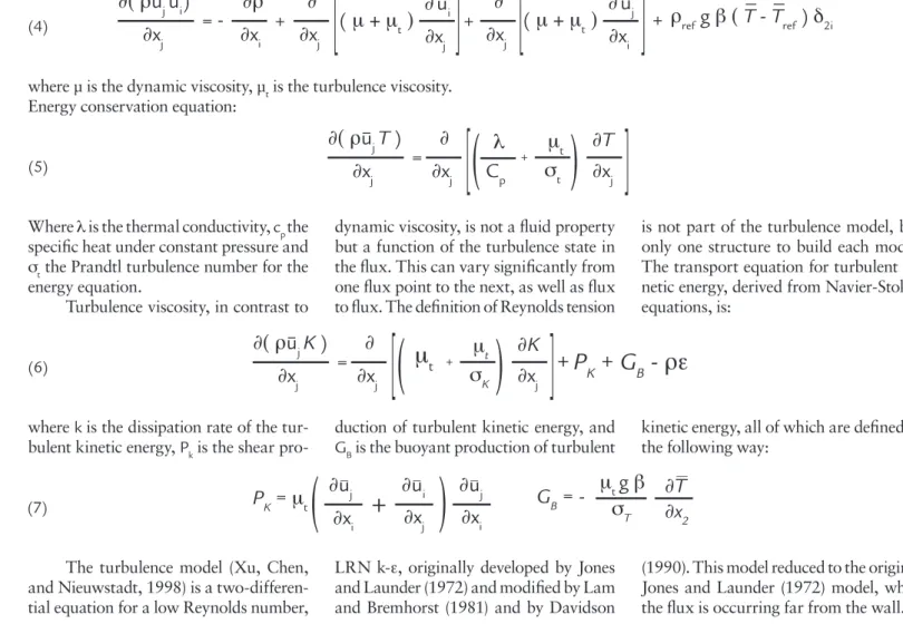
where μ is the dynamic viscosity, μt is the turbulence viscosity. Energy conservation equation:
Where λ is the thermal conductivity, cp the speciic heat under constant pressure and
σt the Prandtl turbulence number for the
energy equation.
Turbulence viscosity, in contrast to
dynamic viscosity, is not a luid property but a function of the turbulence state in the lux. This can vary signiicantly from one lux point to the next, as well as lux to lux. The deinition of Reynolds tension
is not part of the turbulence model, but only one structure to build each model. The transport equation for turbulent ki-netic energy, derived from Navier-Stokes equations, is:
where k is the dissipation rate of the tur-bulent kinetic energy, Pk is the shear
pro-duction of turbulent kinetic energy, and GB is the buoyant production of turbulent
kinetic energy, all of which are deined in the following way:
The turbulence model (Xu, Chen, and Nieuwstadt, 1998) is a two-differen-tial equation for a low Reynolds number,
LRN k-ε, originally developed by Jones and Launder (1972) and modiied by Lam and Bremhorst (1981) and by Davidson
(1990). This model reduced to the original Jones and Launder (1972) model, when the lux is occurring far from the wall.
3. Numerical model
A numerical model for the resolu-tion of the equaresolu-tions for mass conserva-tion, linear movement quantity, energy, turbulent kinetic energy and its rate of dissipation, is the method of inite dif-ferences with formulation for control volumes, developed by Patankar (1980). Power Law interpolation scheme is used to evaluate the luxes on the faces of the control volumes. Pressure-velocity coupling is assured by the algorithm SIMPLEC developed by Van Doormaan and Raithby (1984). The TDMA
(Tri-diagonal Matrix Algorithm) algorithm resolves the system of resultant dis-cretized equations. The block correc-tion algorithm is implemented to con-vergence acceleration. Concon-vergence is achieved when the normalized residual is less than 1x10⁻⁵. The mesh presents
a non-uniform distribution on nodes in both directions of the domain, with the control volumes being less new in the walls and greater in the center of the cavity, Fig. 2a. The number of nodes are 101x 61 points in x and y directions,
respectively. The mesh test presents discrepancies smaller than 2% when the average exit temperature is evaluated.
The air change rate (ACH - air low per indoor volume) as a function of the internal heat source, is presented in Fig. 2b for single-sided ventilation. As the heat load increases, velocity increases too. Results are compared with Eq. (1) and Allocca, Chen and Glicksman (2003) showing excellent agreement between the numerical and semi-analytical models.
Figure 2 a) Computational mesh; b) numerical model validation Momentum conservation equation:
(4)
(5)
(6)
(7)
∂( ρ
u
_ _
ju
i)
∂ρ
_
_ _
∂
x
j∂
x
i∂
∂
x
j∂
∂
x
j=
+
∂
∂
x
j+
-
(
μ + μ
t)
_
u
i∂
∂
x
i+
(
μ + μ
t)
_
u
j[
[
[
[
ρ
refg
β (
T
-
T
ref)
δ
2i∂( ρ
u
_
jT
)
∂
x
j∂
∂
x
jλ
C
pμ
tσ
t=
∂
∂
T
x
j[
(
+(
[
∂( ρ
u
_
jK
)
∂
x
j∂
∂
x
jμ
tσ
K=
∂
K
∂
x
j[
(
μ
t +(
[
+
P
K
+
G
B-
ρε
∂
u
j∂
x
i∂
u
i∂
x
j∂
u
j∂
x
i(
+
(
P
K=
μ
t_ _ _ _
G
B= -
μ
tg
β
Figures 3 and 4 presents isotherm proiles when an internal heat source
(700 W) had its position changed from left to right side in the ofice, respectively.
All cases revel around the source, a bubble with high temperature.
Figure 3
Heat transfer on left side of the office. Heat source away from the exit.
Heat source away from the exit.
Heat source near air exit.
Heat source near air exit. Figure 3 shows the results that
when the internal heat source is on left side, a lower recirculation is formed in the middle plane of the ofice and a large region of discomfort can be seen, with temperatures ranging from 27 to 31 °C. Figure 3a shows results when a cross-ventilation coniguration is used. On top of the ofice appears one region with high temperatures caused by the mass low passing near the heat source.
Temperatures vary from 29 to 35 °C on top of the ofice. Figure 4b shows the results for a single-sided ventilation coniguration. No high temperatures where encountered on top of the ofice.
Figure 4 presents results when the internal heat source is on right side of the ofice. In single-sided ventilation, Fig. 4a, when the heat source is away from the air exit, a large recirculation is formed in almost all of the ofice,
making the temperature remain below 29 °C near the air entrance and rise to 31 °C near on internal heat source. Around the heat source, the temperature reaches 35 °C. However, when the heat source is near the air exit, Fig. 4b, it is observed in practically all the ofice that the temperature remains uniform and equal to 25.5 °C. Only in the heat source region is there observed higher temperature values.
4.2 Internal heat source power
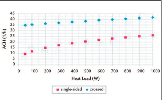
Figure 5 shows air renovation (rate per hour) varying with the heat source for single-sided ventilation and cross ventilation. It is observed,in cross ventilation case, that internal air renovation rate is higher than in single-sided ventilation. This fact is evidenced by the internal vortexes
elevation (Fig. 7). The internal heat source increase causes a higher varia-tion in air renovavaria-tion rate in the single-sided ventilation.
Figure 5
Air change rate versus heat source: single--sided ventilation and cross ventilation.
4. Results
4.1 Internal heat source position
(a) (b)
(a) (b)
Figure 4
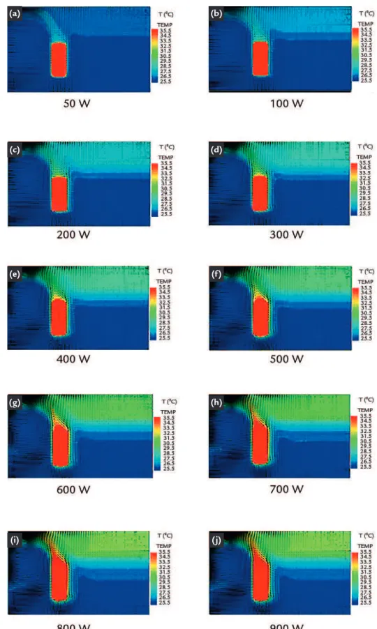
Figures 6 and 7 present isotherms and vector velocities when the heat source is changed from 50 to 900 Watts in single-sided and in cross ventilation, respectively. Results show (Fig. 6) that the temperature increases when internal heat source increases, revealing a bigger stratiication in the temperature proile, due to buoyancy, on right side of heat source. As indicated, on the left side of
heat source, the vortexes created due to the internal heat source inluence that increases the airflow when the heat source increases. However, in this case (single sided ventilation) and depend-ing on the ofice height, the ofice air temperature is maintained within the comfort range (Ashrae 55, 2013). A suitable condition for the air quality cannot be obtained depending on the
occupation proile, represented by the elevation of the heat source level. In crossed ventilation, (Fig. 7), the vortex formation, as also an inluence of the heat source, makes the airlow more uniform in the ofice. In this case, the level of temperature near the source becomes higher as the internal source increases, which could lead to a discom-fort situation in all points of the ofice.
Figure 6 Temperature profile and vector velocity: single-sided ventilation.
(a) (b)
(c)
(e) (f)
(g) (h)
(i) (j)
5. Conclusions
The results show that the tem-perature distribution within the room is inluenced by the location of the internal heat source. The environment can pres-ent appropriate conditions for human comfort whenever the internal source is located next to the outlet, for a speed range between 0.25 m/s to 0.80 m/s.
According to the results, we con-clude that the best coniguration is one in which the heat source is near the exit of air. You can also see that crossed ven-tilation is more effective than unilateral ventilation, even when the heat source is far from the air exit.
In order to obtain an internal
thermal environment that meets hu-man needs of comfort, different sizes, shapes and positions of vents should be studied and modeled under different wind low conditions (direction and speed) taking into account the proile of room occupancy. However this is a nontrivial solution of the problem and
(a) (b)
(c)
(e) (f)
(g) (h)
(i) (j)
(d)
Figure 7
Received: 17 June 2015 - Accepted: 28 October 2015.
ALLARD, F., GHIAUS, C. (ed.). Natural ventilattion in the urban environment: as-sessment and design, London: Earthscan, 2005.
ALLOCA, C., CHEN, Q., AND GLICKSMAN, L. R. Design analysis of single-side natural ventilation. Energy and Buildings, London, v. 35, p. 785-795, 2003. AMERICAN SOCIETY OF HEATING, REFRIGERATION AND AIR
CONDI-TIONING ENGINEERS. ANSI/ASHRAE Standard 62.1: Ventilation for Accep-table Indoor Air Quality, 2004. Inc. Atlanta, GA. 53p.
AMERICAN SOCIETY OF HEATING, REFRIGERATION AND AIR CONDI-TIONING ENGINEERS. ANSI/ASHRAE Standard 55: Thermal Environment Conditions for Human occupancy. New York, USA, 2013. 59p.
AWBI, H. B. Ventilation of Buildings. (2nd Ed.) London: Spon Press, 2003.
DAVIDSON, L. Calculation of the turbulent buoyancy-driven low in a rectangular cavity using an eficient solver and two different low Reynolds Number k-ε turbu-lence models. Numerical Heat Transfer, Part A, v. 18, p. 129-147. 1990.
ETHERIDGE, D., SANDBERG, M. Building ventilation: theory and measurement.
Wiley, Chichester, UK: 1996.
HEISELBERG, P., SVIDT, K., NIELSEN, P. V. Characteristics of airlow from open windows. Building and Environment, v. 36, p. 859-869, 2001.
JONES, W.P., LAUDER, B.E. The prediction of laminarization with two-equation model of turbulence. Int. J. Heat Mass Transfer, v. 15, 1972, p. 301-314.
LAM, C.K.G., BREMHORST, K.A. A Modiied form of the k-ε model for predicting wall turbulence. J. Fluid Eng., v. 103, p. 456-460, 1981.
LI, Y., DELSANTE, A. Natural ventilation induced by combined wind and thermal forces. Building and Environment, London, v. 36, p. 59-71, 2003.
LIPING W., HIEN, W. N. The impacts of ventilation strategies and façade on indo-or thermal environment findo-or naturally ventilated residential buildings in Singapindo-ore.
Building and Environment, London, v. 42, p. 4006 - 4015, 2007.
MARIANA, F. B. Análise numérica da inluência de conigurações de aberturas da fachada e do mobiliário na ventilação natural em ambientes de escritórios. São Paulo: Departamento de Engenharia Mecânica, Escola Politécnica da Universidade de São Paulo, Brasil. 2013. 196 p. (Dissertação de Mestrado em Engenharia Mecâ-nica - in portuguese).
PAPAKONSTANTINOU, K. A., KIRANOUDIS, C. T., MARKATOS, N. C. Nu-merical simulation of air low ield in single-side ventilated buildings. Energy and Buildings, v. 33, p. 41-48, 2000.
PATANKAR, S.V. Numerical heat transfer and luid low. 1980, Hemisphere. New York, 1980.
ROCHA, L. J. C., SOUZA, H. A. The inluence of internal thermal load in natu-rally ventilated buildings. In: IBERIAN LATIN AMERICAN CONGRESS ON COMPUTATIONAL METHODS IN ENGINEERING. Proceedings of CILA-MCE`2008, n. 29, Maceió, AL, Brazil, p. 1-10, nov. 2008.
TANTASAVASDI, C., SREBRIC, J., CHEN, Q. Natural ventilation design for house in thailand. Energy and Buildings, London, v. 33, p. 815- 824, 2001.
VAN DOORMAAN, J. P., RAITHBY G. D. Enhancements of the SIMPLE Method for prediction incompressible luid low. Numerical Heat Transfer, v.7, p. 147-163, 1984. VISAGAVEL, K., SRINIVASAN, P.S.S. Analysis of single-side ventilated and cross
ventilated rooms by varying the width of the window opening using CFD. Solar Energy, v. 83, n. 1, p. 2-5, 2009.
XU, W., CHEN, Q., NIEUWSTADT, F. T. M. A new turbulence model for near-wall natural convection. International Journal of Heat and Mass Transfer, v. 41, p. 3161 – 3176, 1998.
7. References
6. Acknowledgments
The authors gratefully acknowledge the UFOP, FAPEMIG and FG for the inancial support.