Andrei Romanescu, Adrian-Ioan Toma
Power System Fault on Modern Numerical Relays
Modern digital protections, provides comprehensive data in the event of a defect in equipment, data that can be used for the analysis of defects and to remove weaknesses in the system, namely the primary apparatus. Development of numerical protection systems and putting them in power system protection systems enables improved operation in terms of increasing complexity of events.
Keywords: fault, modern digital terminal equipment, software.
1. General considerations
Recorder function allows you to store disturbance events that took place in the primary network distribution system through continuous data collection. Such stored data can be used for various tests. Facilities included in the disturbance re-port function on a modern terminal the following: indications event recorder and fault locator, enabling the saving of many events. All events are recorded in chronological order with the actual times at which they occurred. Information is stored in non-volatile flash memory, avoiding data loss in case of interruption of the supply voltage terminal. [5]
Also new is the advantage of digital terminals providing information on the de-fect to reduce the cut-off time, and also speed up the recharge function of the electrical equipment. Interruption to electricity supply is characterized by two index:
SAIFI = System Average Interruption Frequency Index:
entati lim a
rerupere int
N N
SAIFI=
∑
. (1)Number of consumers affected in each loss is added to all interrupts in one year and the result is divided by the average number of customers, providing the average number of interruptions that has a single customer.
CAIDI – Consumer Average Interruption Duration Index:
ANALELE UNIVERSITĂŢII
“EFTIMIE MURGU” REŞIŢA
(
)
∑
∑
⋅
=
rerupere int rerupere int rerupti intN
D
N
CAIDI
. (2)Interruption duration is mainly a long period of time required to locate the fault, together with the short time necessary corrective measures power refueling. Such a calculation offline fault location can help, therefore, improve CAID index.
2. Obstacles to a precise fault location
Most faults are single-phase earth faults. Most often, the fault is calculated by measuring the loop impedance fault, either directly by the absolute value of phasors, or with changing delta between phasors before and after defect defect, also sometimes supply network is considered as a fault source model affected loops. But all these approaches are limited in precision due to system parameters:
- residual compensation (ZG/ZL,K0): most faults that occur in the electricity transmission system are earth faults. Precision "single ended" fault location depends largely offset by terminal sequence distinct set numerical zero when a fault involving ground. In most cases the exact value of this factor compensation is not known. Thus impedance fault has not often a proportional distribution along the length of the line, because it can vary widely depending on soil composition (sand, stones, water, snow) and type of applied earth (earth tower, cable screens parallel metal pipes).
- parallel lines: In the case of parallel lines, inductive coupling of the current circuits is present. On transposed lines, only the zero sequence system is negatively influenced by this coupling. For load and faults that do not involve ground, the influence of the parallel line may be neglected. With ground faults in the other hand, this coupling may cause substantial errors in the measurement. On a 400 kV double circuit overhead line measuring errors at the end of the line may for example be as large as 35%. Some devices with distance protection functionality have a measuring input that may be applied to measure the ground current of the parallel line. With this measured ground current of the parallel line the impedance calculation may be adapted such that the parallel line coupling is compensated. This parallel line compensation can however frequently not be implemented. The reasons for this are that only a section of the line is in parallel to another line, two or more parallel lines exist or the connection of current transformer circuit between individual feeder bays is not desired by the user for operational reasons. While the selective distance protection function can still be implemented by appropriate zone setting in combination with teleprotection systems, the results of the fault locator without parallel line compensation is often not satisfactory. [1]
transmission networks are often symmetrically transposed with 3 sections. In total, the same impedance for each phase is then approximately achieved for the whole line length. This influencing factor on the accuracy is in this case kept within an acceptable range.
- another factor is the distribution lines that are usually heterogeneous, built as a chain of several segments for both economic reasons and environmental reasons. A typical example is a line that begins with one basic cable with some length, which is maintained by a transposed overhead line conductor arrangement whereby the horizontal.
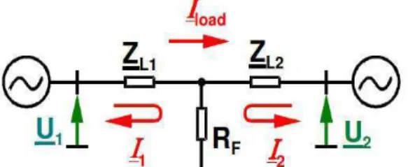
- also even if all the data line are known, there remains a significant influence on the measured impedances: how they would be different fault resistance seen at the ends of a transmission line, the phase shift due to stress, it can be seen in figure 1. [2], [3], [5]
Figure 1. Simple model for the effect of fault resistance at double-ended infeed (load flow from left to right)
At the line end that is exporting the load, the measured reactance is reduced, the phasor (I2/I1)Rf is rotated downwards (figure 2). At the line end that is importing load, the measured reactance is increased, the phasor (I2/I1)Rf is rotated upwards.
Figure 2. Double infed fault resistance affecting the measured reactance
transmission lines normally fulfilled. On faults without ground, the fault impedance will be measured only with an additional resistive part what will not effect the result of the fault locator.
- other influences in the impedance measurement can be considered: capacitive line/cable charging current, CT and VT errors, transients of the voltages, declining DC component of the currents, load taps along the faulted line.
3. How to obtain the precise fault location
If the fault location is known so due solely to the high degree of precision, specialized staff from the operation of power lines and stations can save time during the electrical control defective. Thus the supply of electricity to other parts of the energy system can be restored quickly, providing higher revenues for utilities and also helping to improve outage times CAID index.
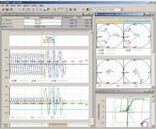
Modern numerical relays also allow you to download data and oscillograms on the fault, which helps the interpretation of the defect, so we obtain release time, during the outburst, the amplitude, some phasors, as can be seen in figure 3.
An accurate fault location is now available for all those who have implemented modern digital relay equipment that exploits them. [4], [5]
4. Positive sequence algorithm
The idea of installing the fault recorders at both ends when a line power, appeared along with marketing and terminal deployment of protection in power systems.
The reason is to use a set of redundant information about the defect to remove some harmful effects that may occur in measurement. But this must be complemented with the other criteria namely, to restrict the calculations to the positive sequence system.
The main advantages of this combination are:
- the data for the positive sequence system are the best and most precisely known grid data, as it can be validated by a three-phase load measurements.
- the algorithm is invariant to fault resistance, as the fault is represented by a current source only.
- the signals of the positive sequence system are invariant to mutual coupling to adjacent circuits (2 or more).
The voltage at the fault location “x” along an ideal line (length L, impedance Z, wave length Ι) is induced by the quantities from either of both line ends l=left and r=right:
( )
( )
( )
l l
l
f
x
cos
h
x
V
Z
sin
h
x
I
V
=
γ
⋅
⋅
−
⋅
γ
⋅
⋅
, (3)( )
(
(
)
)
r(
(
)
)
r rf
x
cos
h
L
x
V
Z
sin
h
L
x
I
V
=
γ
⋅
−
⋅
−
⋅
γ
⋅
−
⋅
. (4)At the fault location “x” the difference between these voltages has to be zero.
( )
x
=
V
fl( )
x
−
V
fr( )
x
=
0
ε
, (5)Also we now switch from solving the fault location analytically at one equation to estimate the most likely fault location at two equations. The voltage condition (5) applies for the positive sequence system as well as for the negative sequence system. Combining the information from both systems with the least-square criterion we get to a one-dimensional function:
( )
( )
( )
2 neg 2 pozdefect
x
x
x
k
=
ε
+
ε
. (6)5. Conclusions
As the algorithm has by principle excluded a lot of the causes for the common errors in fault location, the results obtained are significantly more precise than ever known in the past. The major advantage lies not in optimizing the precision for one special condition only like load compensation or mutual coupling. Instead the algorithm shows a high robustness against all usual causes for errors. All zero-system related influences (data errors, fault resistance, mutual coupling) are excluded by the principle. Even a data error of the positive sequence impedance only reduces the estimation quality and therewith enlarges the interval of confidence, but the indicated location remains correct.
References
[1] ***** Documentaţie tehnică protecții Siemens.
[2] Duşa V., Sisteme moderne pentru comanda şi controlul funcționării
rețelelor electrice, Editura Politehnică Timişoara, 2006.
[3] Fotau I., Electroenergetică, Ed. Universitas, Petroşani 2003.
[4] Kiessling G., Software solution for fault record analysis in power
transmission and distribution. 8th International Conference on
Developments in Power System Protection DPSP, IEE Conf. Publ. 2004. [5] Saha M., Fault location method for MV cable networks. 7th
International Conference on Developments in Power System Protection,
IEE Conf. Publ. 2001.
[6] Vasilievici A., Implementarea echipamentelor digitale de protecție şi
comandă pentru rețele electrice, Editura Tehnică, Bucureşti, 2000.
Addresses:
• Drd. ing. Andrei Romanescu, Universitatea din Petroşani, Petroşani, Hunedoara, [email protected]