BANKS OF AUTOMATIC CAPACITORS IN ELECTRICAL
DISTRIBUTION SYSTEMS: A HIBRID ALGORITHM OF
CONTROL
Helton do Nascimento Alves Benemar Alencar de Souza
Helvio Alves Ferreira
Universidade Federal de Campina Grande
Programa de Pós-graduação de Engenharia Elétrica Av. Aprígio Veloso 882 CEP 58109-970 – Campina Grande
PB C. P.: 10053
Universidade Federal de Campina Grande
Programa de Pós-graduação de Engenharia Elétrica Av. Aprígio Veloso 882 CEP 58109-970 – Campina Grande
PB C. P.: 10053
Universidade Federal de Campina Grande Programa de Pós-graduação de
Engenharia Elétrica Av. Aprígio Veloso 882 CEP 58109-970 – Campina
Grande PB C. P.: 10053
ABSTRACT
A microgenetic algorithm (MGA) in conjunction with fuzzy logic (FL) is proposed for solving the capacitor placement problem. The objective function includes economic savings obtained by energy loss reduction and peak power loss reduction in contrast with acquisition and installation costs of fixed and switched capacitors. Voltage constraints are considered. A simple and efficient method for load flow solution is used, with acceptable CPU time, even for very extensive distribution systems under full load. An approximate load-duration curve divided in different load levels is used to compute energy losses. A 104-bus test system is presented and the results are compared to the solution given by another search technique. This comparison confirms the efficiency of the proposed method which makes it promising to solve complex problems of capacitor placement in distribution feeders.
KEYWORDS: Reactive power control, power distribution lines, microgenetic algorithms, fuzzy logic.
RESUMO
Um algoritmo microgenético aliado a lógica fuzzy é proposto para alocação e programação ótimos de bancos de capacitores em redes de distribuição de energia elétrica. A função objetivo utilizada leva em conta a economia com redução de perdas de potência e de energia e os investimentos associados. Os custos dos bancos de capacitores são separados conforme o tipo (fixos ou chaveados). Limites de tensão de barra são restrições consideradas. O cálculo de fluxo de carga é feito pelo método da soma de potência, uma técnica iterativa simples e eficiente que apresenta tempo de processamento reduzido mesmo nos casos de alimentadores muito extensos e carregados. Para o cálculo das perdas de energia é utilizado a curva de duração de carga segmentada em diferentes níveis. O algoritmo proposto é aplicado a um alimentador de 104 barras e comparado com outras técnicas de otimização. Os resultados confirmam sua eficiência e o credenciam como promissor na solução de problemas complexos de compensação reativa em redes de distribuição de energia elétrica.
PALAVRAS-CHAVE: Controle de potência reativa, sistemas de distribuição, algoritmo microgenético, lógica fuzzy.
Artigo Submetido em 13/11/02 1a. Revisão em 13/09/04; 2a. Revisão em 16/11/04;
1 INTRODUCTION
Reactive compensation in distribution networks is a typical optimization problem of great technical and economic importance which has been faced over five decades. It consists in determining installation points and operation control program of a certain number of capacitor banks in order to maximize the profits obtained from system losses reduction. The extent of the benefits from capacitor banks installation depends on electrical network configuration and its load states. The net profit corresponds to the amount that is saved by reducing losses after discounting the investment in equipment acquisition and its installation.
There are diverse methods for reactive compensation problem solution depending on the available computational resources. Ng et al. (2000) classify these methods into four groups: analytical, numerical programming, heuristic and artificial intelligence based. Analytical methods, as proposed in Neagle & Samson (1956) and Cook (1959), preceded the availability of digital computer. A dynamic programming technique to find capacitor sizes as discrete variables was a pioneering work in Duran (1968). Later, came Fawzi et al (1983), Baldick & Wu (1990) and others. Heuristic methods, as in Mantovani & Garcia (1995) and
Cris et al (1997), are based on rules developed through intuition, experience and judgment. Artificial intelligence based methods have emerged more recently, covering a wide range, according to the specific technique applied. For instance, simulated annealing technique was applied in Rao et al (1996), artificial neural networks were employed in Hsu & Huang (1995) and fuzzy logic was used in Salama et al (2000). Genetic algorithms were presented in Kagan & Oliveira (1998), and Ferreira et al (2002).
In this work, an optimization method based in MGA and FL is proposed and is employed to dimension, locate and control capacitor banks in distribution networks, attempting a compromise between precision and execution time in obtaining global optimal results. The reactive compensation problem is formulated in section 2. Section 3 shows the proposed solution method after a brief review of fundamental concepts relating to microgenetic algorithms and fuzzy logic. In section 4 the proposed method is evaluated by comparing it to others by confronting the results of a common application.
2 PROBLEM
FORMULATION
Capacitor bank size, location and control are determined based on reactive load curve, that is to say, on reactive demand versus time plot. In practice, demand is the mean power (or current) during a specific time interval denominated as demand interval. Therefore, demand varies with time and depends on the point on the feeder where measurements are taken. In ordinary situations, only load curves taken at substation bus (known as feeder load curves) are available and, eventually, curves taken at some special load buses are available too. Thus, individual load curves are considered, almost always, identical to the feeder load curve in order to define the operation control program of switched capacitor banks. This hypothesis simplifies the problem excessively, however it does not affect the final result in a significant way, especially when many loads, all of same type, like residential, commercial, rural or industrial, are supplied (Gönen, 1986).
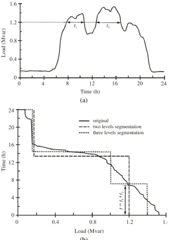
The load curve can be substituted, advantageously, by the corresponding load duration curve, as in figure 1. The convenience of using the load duration curve is due to the fact of it is monotonically decreasing, once it is defined by the points (t, p) such that t is the integral of all the infinitesimal times during which the demand is higher or equal to p. For instance, it is shown how long the demand is higher than 1.2 Mvar in Fig. 1a (times t1 and t2). In Fig. 1b,
the time associated with 1.2 Mvar in the original curve is exactly the sum of t1 and t2. The load duration function is
usually approximated by a two steps ladder function corresponding to the schedules of pick and out of pick. Using more steps can yield better approximation, although this implies larger effort. In this work, three steps functions
0 4 8 12 16 20 24 Time (h)
0 0.4 0.8 1.2 1.6
L
oa
d (
M
var
) t1 t2
(a)
original
two levels segmentation three levels segmentation
1.6 1.2
0.8 0.4
0 0 4 8 12 16 20 24
Load (Mvar)
Ti
m
e (
h
)
(b)
were used. Thus, calculation of energy losses requires calculation of power losses in pick, intermediate and light load levels. Segmented load duration curves are superposed on the original ones as shown in figure 1b.
In the reactive compensation problem, the objective function, to be maximized, represents the economic savings obtained with capacitor banks installation in the distribution network. The capacitor banks usually have nominal capacities that are multiple integers of a standard unit (50, 150 or 300 kvar, for example). On the other hand, the points of possible installation are the feeder buses and therefore, they also form a finite group. Thus, this is evidently a combinatorial optimization problem, whose functional representation is as
3
1 ) ) (
) ( ( )
( )
( )
(
c c
f f
i i i i
m p
k s n
k s n C t ke s P s
P k s f
+
−
∑Δ Δ
+ Δ
= +
= (1)
where:
s is a group of parameters that defines the installation points and the control of the capacitor banks;
kp is the peak power loss cost in $/kW;
kei is the energy loss cost for each level (i =1, 2, 3) in $/kWh;
kf is the fixed capacitors cost ($/kvar) that may aggregate capital, labor, components and accessories costs; kc is the switched capacitor bank cost ($/kvar) that may aggregate capital, labor, pieces and accessories costs; nf is the number of fixed capacitors;
nc is the number of switched capacitor banks; C is the power per module of capacitor bank (kvar);
ΔPm is the peak power loss reduction in kW;
ΔPi is the power losses reduction at each level (i=1, 2, 3), in kW;
Δti is the annual duration of each load level (i=1, 2, 3), in hours.
Any problem solution (not necessarily optimal) is defined by a group of values, s, corresponding to the location and capacity of the banks energized during the time corresponding to load duration of each level. An interesting solution is the one for which f value expressed by equation (1) is maximum, subject to voltage restrictions. That is to say, bus voltages should be within a range of acceptable values.
3 SOLUTION METHODS
In order to find the optimal solution of reactive compensation problem as formulated in the previous section, we propose a two-step method. Initially, using
fuzzy logic, all distribution system buses are appraised to determine the ones which are more adequate to have banks installed on them. Thus, the search space, or the number of viable solutions to be considered in the next step by a microgenetic algorithm, is decreased. The microgenetic algorithm uses the binary code to represent solutions.
3.1 Microgenetic
Algorithms
The genetic algorithms, proposed in Holland (1975), are inspired in the species evolution and according to Darwin’s theory they develop an extensive search in order to find the strongest and the most well adapted chromosome to its environment. The best group of genes is selected by crossover and mutation from others. Genetic algorithms are simple, robust, flexible and able to find the global optimal solution. They are especially useful in finding solution to problems for which other optimization techniques encounter difficulties (Goldberg, 1989). A basic genetic algorithm is constituted by a random creation of an initial population and a cycle of three stages namely:
• Evaluation of each chromosome;
• Chromosomes selection for reproduction and
• Genetic manipulation to create a new population, which includes crossover and mutation.
Each time this cycle is completed, it is said that a generation has occurred. The selection of chromosomes for reproduction and mutation are made by random mechanisms. Besides, the survival criterion is based on a fitness function that evaluates the adaptation of each chromosome from population to the environmental conditions. The disadvantage of GAs is the high processing or execution time associated. That is due to its evolutionary conception, based on random processes that make the algorithm quite slow. However, different methods for reducing processing time have already been proposed, such as more appropriate choice of solution coding and reduction of search space using the specialist knowledge. One of these means is known as microgenetic algorithms, whose processing time is considerably smaller as shown in Delfanti et al (2000) and Chakravarty et al (2001).
because after a certain number of generations the best chromosome is maintained and the rest substituted by randomly generated ones. But, on the other hand, it requires adoption of some preventive strategy against loss of diversity in population.
3.2 Fuzzy
Logic
Fuzzy logic allows a computational representation of heuristic knowledge about a specific problem. Ever since 1965 when Zadeh proposed FL, it has been extensively applied in several areas of knowledge to solve mainly control and optimization problems (Zadeh, 1965). In power systems area, it has been applied for stability studies (Huang, 1992), to solve the problem of electrical energy supply re-establishment (Delbem et al, 1998) , for reactive compensation in distribution network (Salama et al, 2000) and others. Fuzzy logic has also shown good results when combined with genetic algorithms, as presented in Su et al (2001) and Herrera & Lozano (2001).
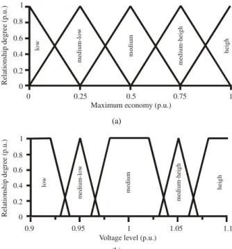
Basically, it is necessary to identify the main variables that have influence on the decisions to be taken and quantify its values in relevance levels. A relationship function establishes the profile of these variables by expressing the compatibility degree of each one of them with previously known information. According to these situations, rules are established and necessary actions to a solution are determined. A process called defuzzification, which consists in all variables interaction through stochastic techniques, obtains final values. In the capacitor allocation problem, rules are established to determine the convenience of having a bank installed in a particular bus or not. The variables bus voltage and maximum economy are used to establish the group of fuzzy rules. Relationship functions of these variables are shown in figure 2. Those variables indicate lack of capacitive reactive in the distribution network and determine the allocation sensibility degree of each bus, as shown in figure 3. The summary of fuzzy rules is presented in table 1.
3.3 A Hybrid Method
From our studies and experiments with several methods reported in the literature, we propose still another method that consists of the following steps:
1. Calculate bus voltages, power and energy losses considering the original feeder configuration, or in other words, without any capacitor which is supposed to be installed;
2. Calculate the maximum savings obtained with capacitor installation at one single bus;
3. Calculate the maximum savings obtained with capacitor installation at several buses;
4. Apply fuzzy heuristics to determine a subgroup of buses in which capacitor banks installation would be more advantageous;
5. Adopt the economic savings expressed in equation (1) as fitness function;
Table 1 - Summary of Fuzzy Decision Rules
Voltage Ö economyØ low
medium
low medium
medium
high high
Low medium
low
medium
low low low low
medium
low medium
medium low
medium
low low low
Medium medium medium medium
low low low
medium high
medium high
medium
high medium
medium
low low
High high medium
high medium
medium low medium low Sensibility (p.u.) R ela ti on sh ip d eg ree ( p .u .)
0 0.25 0.5 0.75 1 0 0.2 0.4 0.6 0.8 1 low me di u m -l o w med iu m m edium -he ig h hei g h
Figure 3 - Relationship function of bus allocation sensibility.
Maximum economy (p.u.)
Re la ti on sh ip d eg ree ( p .u .)
0 0.25 0.5 0.75 1 0 0.2 0.4 0.6 0.8 1 lo w m ed ium -l ow me d iu m med iu m -h ei gh hei g h (a)
Voltage level (p.u.)
R el at ions h ip d egr ee (p .u .)
0.9 0.95 1 1.05 1.1
0 0.2 0.4 0.6 0.8 1 lo w m edi um -l ow m edium medi um-h eigh he ig h (b)
6. Based on the subgroup determined in step 4, randomly create a n size initial population and go to step 8; 7. Based on the subgroup determined in step 4, randomly
create an n-1 population and add to it the best chromosome from the last generation;
8. Determine the fitness function of each chromosome; 9. Choose m chromosomes from the present population
using the tournament method. Make crossover operation using pairs of chromosomes from this subgroup;
10. Calculate the adaptation index of the new chromosomes;
11. Repeat steps 9 and 10 until the population reaches an homogeneous degree previously chosen;
12. Find the best chromosome, keep it and discard the others;
13. Repeat steps 7 to 12 g times or until the best individual is identified after h consecutive generations.
The number m of chromosomes chosen for crossover is previously determined, as are g and h. The tournament method is a process in which a population subgroup is randomly formed and from which the most well adapted individual is elected for crossover.
In this work, information from each bus is coded in one byte. The lower two bits are related to the peak load level, the next three to the intermediate load level and the last three to the light load level. An example of chromosome is shown in figure 4. At bus 1 there is no capacitor bank; at bus 2 there are two switched banks in intermediate load and three in peak load; at bus n there are two fixed banks, five switched banks in intermediate load and two switched banks in peak load.
The genes that are copied from parents to their off springs are randomly chosen as shown in figure 5. A logical mask is applied to one of the parents and the complementary
mask is applied to the other one.
4 APPLICATION
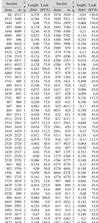
The hybrid method is applied to a 104-bus feeder whose line and load data can be found in tables 2 and 3. This system is derived from a portion of a distribution system from the northeast of Brazil. The line voltage in substation is 13.8 kV and the power factor is 0.96 for all loads.A
five-Figure 4 - The chromosome structure.
Figure 5 - The reproduction mechanism used.
Table 2 – 104-Branch System Data
Section Length. Load Section length. Load
from to
c a
b (km) (kVA) from to c a
b (km) (kVA) SE 4512 1 0,278 45,0 3878 3920 2 0,03 150,0 4512 3440 1 0,384 75,0 3920 3921 2 0,036 75,0 3440 897 1 0,08 75,0 3934 2995 2 0,068 150,0 897 3690 2 0,178 30,0 2995 3780 2 0,108 45,0 3440 4009 1 0,246 45,0 3780 4388 2 0,21 45,0 4009 895 2 0,072 75,0 4388 4702 2 0,134 53,0 895 896 2 0,194 45,0 4388 3995 2 0,254 45,0 896 4010 2 0,06 75,0 3995 3996 2 0,184 45,0 4009 4522 1 0,198 75,0 2989 879 3 0,186 15,0 4522 1236 2 0,182 75,0 879 3738 2 0,13 45,0 1236 2519 2 0,124 75,0 879 4206 3 0,076 30,0 1236 4931 2 0,068 45,0 4206 1553 2 0,074 15,0 4931 4932 2 0,128 75,0 4206 876 3 0,106 0,0 4522 4460 1 0,442 300,0 876 877 2 0,118 45,0 4460 3741 1 0,042 75,0 877 878 2 0,148 45,0 3741 3833 2 0,132 45,0 878 1264 2 0,148 45,0 3741 889 2 0,154 75,0 876 3431 3 0,498 45,0 889 4414 2 0,106 75,0 3431 829 3 0,02 0,0 4414 2676 2 0,072 45,0 3431 827 3 0,086 45,0 2676 891 2 0,342 75,0 827 828 3 0,098 0,0 3741 887 1 0,148 0,0 828 825 3 0,126 112,5 887 886 2 0,248 75,0 825 822 3 0,106 0,0 887 884 1 0,062 45,0 822 4013 2 0,17 45,0 884 883 1 0,196 0,0 4013 824 2 0,198 15,0 883 2511 2 0,038 75,0 822 821 3 0,106 45,0 2511 2514 2 0,018 75,0 821 4211 3 0,1 45,0 2514 2943 2 0,072 112,5 4211 2941 3 0,048 0,0 2943 3410 2 0,034 75,0 2941 820 2 0,316 75,0 3410 3429 2 0,182 112,5 2941 819 2 0,15 75,0 3429 2525 2 0,072 75,0 4211 816 3 0,158 0,0 2525 2526 2 0,078 75,0 816 817 2 0,11 112,5 2526 2524 2 0,062 30,0 817 4023 2 0,064 45,0 3429 3430 2 0,04 75,0 816 807 3 0,038 0,0 3430 2527 2 0,02 75,0 807 1275 3 0,322 75,0 2527 2528 2 0,09 75,0 1275 4766 3 0,156 45,0 2528 2529 2 0,066 75,0 4766 4275 2 0,348 45,0 883 882 1 0,144 45,0 4275 4276 2 0,14 45,0 882 1594 3 0,09 30,0 4276 4684 2 0,148 45,0 1594 881 3 0,058 30,0 4684 4278 2 0,196 45,0 881 2725 3 0,162 0,0 4278 4279 2 0,306 45,0 2725 4839 2 0,254 15,0 807 808 2 0,048 75,0 4839 3130 2 0,034 225,0 808 809 2 0,146 45,0 2725 4220 3 0,19 45,0 809 810 2 0,164 75,0
4220 880 3 0,044 0,0 810 811 2 0,08 75,0
880 4441 3 0,084 300,0 811 813 2 0,138 75,0 4441 2989 3 0,094 0,0 813 4924 2 0,142 45,0 2989 2992 2 0,224 150,0 813 812 2 0,068 15,0 2992 3934 2 0,054 0,0 813 815 2 0,236 112,5 3934 3877 2 0,07 0,0 815 3110 2 0,188 45,0 3877 4085 2 0,148 15,0 815 4262 2 0,2 45,0 3877 3878 2 0,108 150,0 4262 4263 2 0,204 45,0
year planning horizon is considered. A yearly load growth of 21.0% is assumed. Table 4 shows the load levels (according to the loads presented in table 2), number of hours in operation and energy loss cost. The annual cost of peak power loss (kp) is $ 2 6 0/kW/year. Modules of 50 kvar each form the capacitor banks. The costs are indicated in table 5. For validation purposes the problem is also solved by a genetic algorithm and a microgenetic one.
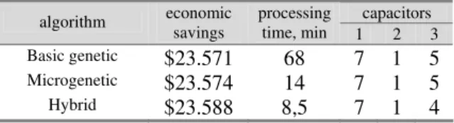
The basic genetic algorithm uses a 300-chromosome population with crossover and mutation rates of 60% and 4% respectively. The microgenetic algorithms crossover rate is 80% and their populations are constituted by 20 chromosomes (without FL) and 10 chromosomes (with FL). The proposed hybrid method gave the result shown in table 6 that is being compared to the results given by the other two techniques. Fixed capacitors (type 1) predominate in the three solutions and are followed by type 3 switched capacitors. Type 3 are the ones that operate only during peak intervals.
Incorporating fuzzy logic in the microgenetic algorithm makes it more efficient because it reaches a better result with small processing time. From the 104 buses, 57 are previously selected for possible capacitor banks installation (54,8%). This pre-selection is related to the feeder configuration and its load conditions.
5
CONCLUSION
The genetic algorithms are very appropriate to solve the size, location and control problems of capacitor banks in distribution networks. However, microgenetic algorithms are more efficient to solve this kind of problem because they are faster and give nearly global optimal solutions. The microgenetic algorithms become even more efficient when specialist’s knowledge about the problem is included. This is possible by using fuzzy logic. In this way, it is possible to reduce the search space and consequently decrease the execution time, increasing the chance to reach the global optimal solution.
Currently, the hybrid method is being applied to longer feeders and the relationship functions are being tuned. The results obtained from these new studies confirm the efficiency of the method and make it promising in the solution of complex reactive compensation problems in electrical distribution networks.
REFERENCES
Baldick, R. and F.F. Wu, (1990). Efficient Integer Optimization Algorithms for Optimal Coordination of Capacitors and Regulators. EUA, IEEE Transactions on Power Systems, Vol. 5, No. 3, pp. 805-812.
C Su, C.T., G.R. Lii, C.C. Tsai. (2001). Optimal Capacitor Allocation Using Fuzzy Reasoning and Genetic Algorithms for Distribution Systems, Mathematical and Computer Modelling, EUA, Vol. 33: pp. 745-757.
Chakravarty, S., R. Mittra and N. R. Willians. (2001). On the Application of the Microgenetic Algorithm to the Design of Broad-Band Microwave Absorbers Comprising Frequency-Selective Surfaces Embedded in Multilayered Dieletric Media. IEEE Transactions on Microwave Theory and Techniques, EUA, Vol. 49, No. 6, pp. 1050-1059.
Cook, R. F. (1959). Analysis of Capacitor Application as Affected by Load Cycle. AIEE Transactions, EUA, Vol. 78, No. 10, pp. 950-957.
Cris, M., M. M. A. Salama and S. Jayaram. (1997). Capacitor Placement in Distribution Systems Using Heuristic Search Strategies. IEE Proceedings Generation, Transmission and Distribution, UK, Vol. 144, No. 2, pp. 225-230.
Delbem, A. C. B., N.G. Bretãs and A. O. Carvalho. (1998). Um Algoritmo de Inteligência Artificial com Heurísticas Fuzzy para Restabelecimento de Energia
Table 4 - Load Levels, Hours of Operation and Energy Loss Cost
Load Level Hours of Operation Energy Loss Cost ($/kWh)
Level L1 L2 L3 T1 T2 T3 KE1 KE2 KE3
Value 0,4 0,24 0,2 1829 3150 3661 1,0 0,7 0,4
Table 5 - Capacitor Banks Cost
type cost ($/kvar) fixed 1.0 switched 1.3
Table 6 - The Solutions Given by Different Methods
capacitors algorithm economic
savings
processing
time, min 1 2 3
Basic genetic $23.571 68 7 1 5
Microgenetic $23.574 14 7 1 5
Hybrid $23.588 8,5 7 1 4
Table 3 -Impedance Values of Conductors
Cab Conductor R (ohms/km) X (ohms/km)
1 336,4 MCM 0,1904 0,3766
2 4 CA 1,5325 0,4705
em Sistemas de Distribuição Radiais. XII Congresso Brasileiro de Automática, pp. 1703-1708.
Delfanti, M., P. G. Granelli, P. Marannino and M. Montagna. (2000). Optimal Capacitor Placement Using Deterministic and Genetic Algorithms. IEEE Transactions on Power Systems, EUA, Vol. 15, No. 3, pp. 1041-1046.
Duran, H. (1968). Optimun Number, Location and Size of Shunt Capacitors in Radial Distribuition Feeders, A Dynamic Programming Approach. IEEE Trans. Power Apparatus and Systems, EUA, Vol. 87, No. 9, pp. 1769-1774.
Fawzi, T.H., S. M. El-Sobki and M.A. Abdel-Halim. (1983). New Approach for the Aplication of Shunt Capacitors to the Promary Distribution Feeders. IEEE Trans. Power Apparatus and Systems, EUA, Vol. 102, No. 1, pp. 10-13.
Ferreira, H. A., B. A. Souza and H. N. Alves. (2002). Optimal Capacitor in Electrical Distribution Systems Using a Genetic Algorithm, Latin America IEEE/PES T&D 2002, São Paulo, 18-22 of march, paper 188. Goldberg, D. E. (1989). Genetic Algorithms in Search,
Optimization and Machine Learning. Addison-Wesley, 412p.
Gönen, T. (1986). Electric Power Distribution Systems Engineering, , Mcgraw-Hill Book Co., New York, 739p.
Herrera, F. and M. Lozano. (2001). Apaptive Genetic Operators Based on Coevolution with Fuzzy Behaviors. IEEE Transactions on Evolutionary Computation, EUA, Vol. 5, No. 2, pp. 149-165.
Holland, J. H. (1976). Adaptation in Natural and Artificial Systems. University of Michigan Press, 211p.
Hsu, Y. and H. Huang, (1995). Distribution System Service Restoration Using the Artificial Neural Network Approach and Pattern Recognition Method. IEE Proc. Gener. Transm. Distrib., vol, 142, No. 5, pp. 251-256.
Kagan, N. and C. C. B. Oliveira. (1998). Utilização de algoritmos genéticos para a minimização de perdas em redes de distribuição de energia elétrica, Brasil, III Congresso Latino Americano de Distribuição de Energia Elétrica, pp. 587-591.
Mantovani, J.R.S. and A.V. Garcia. (1995) A Heuristic Method For Reactive Power Planning. The 1995 IEEE Power Engineering Society Winter Meeting, EUA, Paper 95 Wm 132-1 Pwrs.
Neagle, N. M. and D. R. Samson (1956). Loss Reduction from Capacitors Installed on Primary Feeders. AIEE Transactions, EUA, Vol. 75, pp. 950-959.
Ng, H. N. M. M. A. Salama and A. Y. Chikhani. (2000). Classification of Capacitor Allocation Techniques. IEEE Transactions on Power Delivery, EUA, Vol. 15, No. 1, pp. 387-392.
Rao, A. S. G., K. R. Rao and T. Ananthapadmanabha, A.D. Kulkarni. (1996). Knowledge-Based Expert System for Optimal Reactive Power Control in Distribution Systems, Electrical Power & Energy Systems, Vol. 18, No. 1, pp. 27-31.
Salama, M. M. A. and A. Y. Chikhani, H. N. Ng. (2000). Capacitor Allocation by Approximate Reasoning: Fuzzy Capacitor Placement. IEEE Transactions on Power Delivery, EUA, Vol. 15, No. 1, pp. 393-398. Zadeh, L. A. (1965). Fuzzy Sets, Information and Control,