ABSTRACT: According to motion characteristic of an asymmetric rolling missile with damage in, a three-channel controlled model is established. The controller which is used to realize non-linear tracking and decoupling control of the roll and angle motion is introduced based on an improved trajector y linearization control method. The improved method is composed of the classic trajectory linearization control method and a compensation control law. The classic trajectory linearization control method is implemented in the time-scale separation principle. The Lipschitz non-linear state observer systematically obtained by solving the linear matrix inequality approach is provided to estimate state variables and unknown parameters, and then the compensation control law utilizing the estimated unknown parameters improves the TLC method. Simulation experiments show that the adaptive decoupling control ensure tracking performance, and the robustness and accuracy of missile attitude control are ensured under the condition of the system parameters uncertainty, random observation noise and external disturbance caused by damage in.
KEYWORDS: Asymmetric, Rolling missiles, Control, Improved TLC, Lipschitz adaptive observer.
The Control of Asymmetric Rolling
Missiles Based on Improved Trajectory
Linearization Control Method
Huadong Sun
1, Jianqiao Yu
1,
Siyu Zhang
1INTRODUCTION
he structure or the aerodynamic asymmetric phenomenon is common for many rolling missiles.
Such unintended asymmetric phenomenon is oten caused by two reasons: machining or assembling misalignment and body or in structural damage by large external forces during the launch or the light.
Because of uncertainty and random asymmetric factors, the asymmetric rolling missile system is a complex non-linear system with uncertainty parameters. he research on dynamic modeling and control of asymmetric rolling missile is an important problem.
Scholars carried out in-depth research in the dynamic and modeling of asymmetric aircrat. Asymmetric aerodynamic characteristics were the irst to be of concern, and wing bending and impact damage were studied by the use of wind tunnel experiments(Render et al. 2007; Djellal and Ouibrahim 2008; Render et al. 2009). he dynamic problems were also the focus of the study. For an asymmetric rolling missile, when the roll rate nears to the natural frequency of pitch or yaw motion, the roll rate of the missile may be locked and maintained in the natural frequency, and the phenomenon is named lock-in. If the angle of attack of the missile becomes bigger and bigger, the catastrophic yaw happens. Since the lock-in mechanism and the phenomenon of catastrophic yaw were revealed (Murphy 1989), the research about asymmetric rolling missile motion model and dynamic behaviors are widely investigated. By the use of coupling angular motion and roll motion of 5-degrees-of-freedom equations, diferent dynamic behaviors such as limit
1.Beijing Institute of Technology – School of Aerospace Engineering – Beijing – China.
Author for correspondence: Huadong Sun | Beijing Institute of Technology – School of Aerospace Engineering | Tiyu N Rd, Haidian | Beijing, 10081 – China | Email: [email protected]
and chaos of asymmetric rolling missile were studied (Murphy 1989; Ananthkrishnan and Raisinghani 1992; Mikhail 1998; Tanrkulu 1999; Sun et al. 2015; Morote 2007; Morote et al. 2013). Bifurcation analysis was introduced to investigate the evolutionary process of dynamic behaviors such as lock-in and limit circle in quantitatively and qualitatively ways (Sun et al. 2015).
he control method of investigation and controller design are important things for an asymmetric rolling missile. Two types of in damage were studied in the modeling and missile guidance law designing, and the classical proportional-integral-derivative (PID) control method was used (Harris and Slegers 2009). Research on non-linear control for the uncertainty parameters aircrafts was quite extensive, and it has been a hot issue of scholar’s attention. Non-linear controls, such as robust adaptive (Rajagopal et al. 2010), sliding mode (Yang et al. 2012), and dynamic inversion (Nguyen et al. 2006), were applied in the presence of asymmetry of aircrat and spacecrat with uncertainties or other factors. Among these methods, trajectory linearization control (TLC) is a simple but efective gain scheduling means to solve non-linear and uncertainty system. TLC has been successfully applied in missiles (Mickle and Zhu 2001), robots (Liu et al. 2003), aircrats (Zhu and Huizenga 2004), and other objects (Bevacqua et al. 2004; Su et al. 2013).
However, the control performance of TLC method can signiicantly be reduced or even infeasible in the presence of serious uncertainties (Zhu and Huizenga 2004). Besides, for most physical missile systems, another major diiculty for TLC are strong external disturbances and model uncertainties due to either constant or sudden changes. TLC faces a big challenge to deal with diiculties of cross coupling, modeling errors, external disturbances, and sensor noise efectively. In addition, the complex dynamic behaviors, such as lock-in, limit circle, and even chaos phenomenon, increase the control diiculty, and furthermore the complexity is exacerbated because of strong cross yaw-roll dynamical coupling caused by the missile rotation. Improving TLC algorithm is an issue of great signiicance.
his paper aims at designing a good performance control system for asymmetric rolling missiles and developing an improved method for TLC algorithm. Firstly, considering the external force caused by damage fin, a three-channel controlled model for asymmetric rolling missiles is established by the time-scale separation principle. Secondly, control law is presented using improved TLC method in which an adaptive compensation control law is added based on Lipschitz observer.
Lastly, simulation experiments are carried out, and the results show that the performance of three-channel attitude control is well-exhibited. he control efectiveness of the proposed improved method is more robust then TLC.
MOTION MODEL
For an aerodynamic asymmetric cruciform inned missile with ixed rolling rate, the moment equations expressed by the complex angle of attack ξ and the complex angular velocity μ can be given in the aeroballistic axes (Murphy 1963), illustrated in Fig. 1. For a controlled missile with air rudders, compared with the aerodynamic force produced by the body, the air rudder force is a small term. Neglecting the small force produced by the rudder but taking the moment into consideration, the motions can be transformed to the body ix axes and provided as:
where: CLα is the lit force coeicient; ϕ is the roll angle; CNpαis the Magnus force coeicient; γ = cos(√α2 + β), being α and β angles of attack and side-slip; ktis the transverse radius of gyration; CMpα is the Magnus moment coeicient; CMα is the normal moment slope coeicient; τ = 1 − Ix/Iy, being Ix and Iy axial and transversal moment of inertia; CMq is the damping moment coeicient; CD is the drag force coeicient; CM0eϕM0 is
the asymmetric moment coeicient, being CM0 the amplitude and ϕM0 the phase; CMδ is the control moment coeicient; the superscript * means a multiplication by ρSd/(2m), being S reference area , ρ air density, and m the mass.
Figure 1. Axes of missile motion.
ϕ
Z O
Z
Y
Y YOZ: Body fix axes
YOZ: Aeroballistic axes
Cm: static moment α
α β
ξ
ξ
β ~
~
~
~ ~ ~
~ ϕ
ϕM0 CM0
Cm
(1)
In Eqs. 1 and 2, ξ΄ and μ΄ are the derivatives of ξ and μ with respect to the independent variable l, which has the form l = d–1 ∫
0t V dt, being V the velocity of the missile, d the reference length and t the time; ξ = β + iα is the complex angle of attack in the body ix axes, and μ = q + ir is the complex angle velocity. kt–2 C*M0eiϕM0performs the uncertainty provided by the small asymmetric term. δ = δ + iδy is the rudder delection angle in the yaw and pitch channels.
For rolling missiles, canted ins causing a constant roll moment Kδ are usually used to generate a design steady-state roll rate. Induced roll moment must be taken into account in the rolling motion besides roll moment and roll damping moment. he induced roll moment can be expressed in a simply form varying with α. he roll motion then has the form:
hus, Eqs. 1, 4 and 5 constitute the asymmetric rolling missile motion model in three-channel control. Slow loop variables Ω = (β, α, ϕ)T and fast loop variables ω = (q, r, p)T are deined, respectively, being q, r, and p yaw, pitch, and roll rates in body ixed axes. Ω responding slowly is the Euler angle vector, and ω responding fast is the angle velocity vector.
According to the time scale separation principle, Eqs. 1, 4 and 5 are rewritten in the forms:
where: Kp equals to –(CD* + ka –2 Clp *) , being ka the axial radius of gyration and Clp the roll damping moment; Kδis the roll moment by canted ins; Kn is the induced roll moment coeicient; CMδr is the rolling control moment coeicient; δr is the rudder delection angle in the roll channel.
When the asymmetric uncertainties are severe, they cannot be simply expressed in a constant. As shown in Fig. 2, when a in surface is seriously damaged, the uncertainty interference caused by the lost lit dealt as an external force can be approximated as a function of the angle of attack α. Equations 2 and 3 are rewritten into the following forms, respectively:
X Y V
Z MzF = F1α
MzF = F2α
F = f (α)
Figure 2. Structural damage schematic diagram.
where: F1 and F2 are the uncertainty force in the angle and roll motion caused by damage.
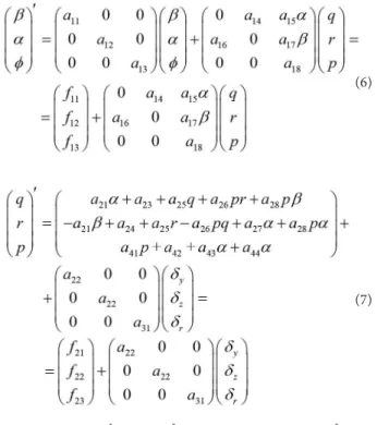
where: a11 = –CLα* , a12 = –CLα* , a13 = 0, a14 = –1, a15 = –(CNpα +* 1), a16 = 1, a17 = –a15, a18 = 1, a21 = kt –2C* Mα, a22 = kt –2C* Mδ, a23 = k–2t C* M0 cos(ϕM0), a24 = k–2t C* M0 sin(ϕM), a25 = k–2t C* Mq + C* D), a26 = τ, –1 – τ, a27 = F1, a28 = k–2t C* Mpα, a31 = k–2t C* Mδ
,
a41 = –Kp a42 = –Kδ,
a43 = –Kn, a44 = F2.
TLC PRINCIPLE
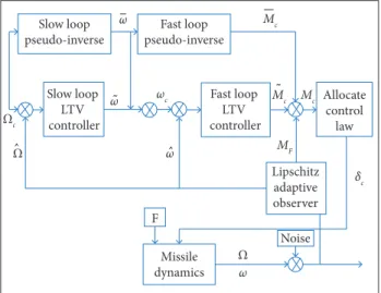
As shown in Fig. 3, TLC design method is consisted of two parts. One is forward loop designed by the use of non-linear dynamic inverse method, which changes the trajectory tracking problem into error adjustment problems. Another is state feedback loop designed by the use of linear varying system parallel-diferential (PD) spectral theory, which ensures the robustness of the system with model errors. Control model can be represented in two parts as slow and fast loop. he slow
(3)
(4)
(5)
(6)
one is missile attitude angles loop, and the fast one is angular velocity loop. The core issue for TLC is the design of gain scheduling control law.
NOMINAL CONTROL COMMAND COMPUTING Let us consider:
Slow loop pseudo-inverse
Slow loop LTV controller
Fast loop LTV controller
Allocate control
law
Missile dynamics
Noise F
Lipschitz adaptive observer Fast loop
pseudo-inverse
ω
ω
Ω
Ω Ωc
ω
˜
ˆ
ˆ
˜
ω ωc
Mc
MF Mc
δc Mc
Figure 3. Control system coniguration.
SLOW LOOP CONTROLLER DESIGN
According to TLC method, linear time-varying proportional-integral (PI) regulator is usually designed to track the augmented vector error. he augmented vector can be expressed as:
Meanwhile, the slow loop in Eq. 6 can be augmented as:
where:, f~ 1 = [β, α ,ϕ, f11, f12, f13]T and g~1 = [O3 gT 1]T, and O3 is a zero matrix 3 × 3.
Equation 11 is linearized in (X1, ω). he state and input matrices of the linearized Eq. 11 are represented as:
he expected error dynamics characteristic of the slow closed loop is represented as:
where: α1,jk, j = 1, 2, 3, k = 1, 2, varying with time, are obtained
from the closed-loop quadratic PD eigenvalues. he state feedback matrix K1(t) is deduced from:
Nominal Ω = Ωc command of slow loop is the expected control command of missile. Because g1 is invertible, the nominal
command of slow loop is given by:
where: ω is also the nominal command of fast loop. hen the nominal control moment is represented as follows:
(8)
(11)
(12)
(13)
(14)
(9)
(10)
(15)
Derivatives Ω and ω are computed from Ω and ω using a pseudo-diferentiator represented by the transfer function:
Equation 10 is also a low-pass ilter and not only passes through input signal but also avoids output saturation by high-frequency noises.
. .
B = g
,1
1X1ωB = g
,1
1X ω1
Dynamic error augmented vectors can be deined as:
FAST LOOP CONTROLLER DESIGN
Following the same method to deine fast loop dynamics augmented vector error,
the estimations of state variables and unknown parameters. Lipschitz observer is a common non-linear system state observer and still has a good observation performance for strongly non-linear systems with noise disturbances. Speciic design process of Lipschitz observer is characterized as follows (Rajamani 1998; Zemouche and Boutayeb 2013; Pourgholi and Majd 2011).
For a classical non-linear system with unknown parameters:
augmented equation of fast loop has the form:
he fast loop linearization state matrix and input matrix are provided as:
where: u = [δy δz δr]T.
Expected error dynamics characteristic matrix of the fast closed loop can be expressed as follows:
where: α2,jk, j = 1, 2, 3, k = 1, 2, can be given according to
PD spectral theory similarly.
State feedback matrix K2 (t) is deduced from the equation:
he fast loop control input can be expressed as:
where: A and C are linear matrices; x∈ℝn is the state vector;
u∈ ℝm is the control vector; y∈ ℝp is the output vector; F ∈ ℝl is an unknown steady bounded parameter; and |F|| ≤ yl. For
all (x,y) and all u the pair (C,A) is observable.
For Eq. 23, make the following three hypotheses (Rajamani 1998; Zemouche and Boutayeb 2013):
Hypothesis (1): non-linear functions Φ (x,u)and Ψ (x,u) are both uniform boundedness, and ∀x∈ ℝnand ∀u∈ ℝm, Lipschitz condition is satisied as follows:
where: y2 > 0 and y3 > 0 are Lipschitz constants.
Hypothesis (2): there exist a gain matrix and a positive number ε making algebraic Riccati equation:
have a positive deinite solution P, where γ = γ2 + γ1γ3.
Hypothesis (3): there exists a vector function h(x,u) making the positive deinite solution P satisfy:
If the Hypotheses (1) to (3) conditions are satisied, then the observer of the Eq. 23 is given as follows:
(16)
(17)
(18)
(23)
(24)
(25)
(26)
(27) (19)
(20)
(21)
(22)
LIPSCHITZ ADAPTIVE OBSERVER DESIGN
State observer design is an essential process for a control system, and the compensation control law design is based on
where: ρ is a constant parameter to adjust the estimation
error and F ˆ = [F ˆ1, F ˆ2]. L is the gain matrix of the observer. L is obtained by transforming Riccati equation into the linear matrix inequality (LMI) problem (Pourgholi and Majd 2011). ,
In this paper, according to the Lyapunov stability conditions, the design of observer is changed to the process of solving LMI group. LMI problem is equivalent to ind a deinite solution P > 0 and a positive number η > 0 satisies the inequality equation:
By solving the above inequality (Eq. 28), L can be obtained as:
COMPENSATION CONTROL LAW DESIGN
Compensation control law is given according to the estimated parameter F ˆ. he control law can compensate for the interference generated by the F in the pitch and roll channels, and then TLC control performance is improved. Furthermore, in order to improve the yaw channel performance, the state feedback stabilization is increased. Compensation control law is shown as follows:
where: Kβis the adjusting gain.
he improved TLC control law based on Lipschitz adaptive compensation is then proposed as:
SIMULATION
Simulation analysis for an asymmetric rolling missile is performed, and system parameters are:
a11 = −2.3×10⁻⁴, a12= −2.3×10⁻⁴, a13= 1, a15= 1, a21= −1.4×10⁻⁵, a22= 1×10⁻⁵, a23= −2.4947×10⁻⁷, a24= 2.4947×10⁻⁷, a25= −1.5×10⁻⁴, a26= 0.99, a28= −1×10⁻⁵, a31= 9×10⁻⁴, a41= −1.3×10⁻³, a42= 5×10⁻⁶, a43= 5.2×10⁻⁴, F1 = 0, F2=
0.
SIMULATION 1
Equations 6 and 7 can be easily transformed into a standard non-linear form with unknown parameter as Eq. 23. In order to verify the state observation and the noise suppressing performance of Lipschitz state observer, external forces F1 and F2are taken to 0. In addition, system state observations oten
have some uncertainty. For example, the output values of the measurement system are usually superimposed with white noise. In order to represent the sensor noise, the output values are superimposed on white noise in simulation. Meanwhile, the actual value of the aerodynamic parameters increases by 20% compared with the estimated one.
he expected tracking states “command” in yaw, pitch and roll channels are βc, αc and pc, respectively. It means that the
motion states β, α and p of the missile are expected to change as
the commands βc, αc and pc require, as shown in Fig. 3. he
specific command for βc in yaw channel is a square wave;
the speciic command for αc in pitch channel is a step response;
and the speciic command for pc in roll channel is a constant.
hese three commands are all passed through a low-pass ilter 5s/(s + 5).
According to Eq. 29, let us take the gain matrix L as:
Time [s]
10 5
0 15 20 25 30 35
β
[rad]
-0.02 0 0.02 0.04
0.06 TLC
TLC + Lipschitz observer
Command
Figure 4. Effectiveness of yaw control. (28)
(29)
(30)
(31)
he simulation results are shown in Figs. 4 to 6. he expected motion states in the three channels of β, α and p are meant to
track the commands βc, αc and pc which are marked in black
line. To track the same commands βc, αc and pc, diferent control
observer is used, noise is efectively suppressed. It is apparent that the controller has good tracking performance even with output noise interference.
Figure 6. Effectiveness of roll control.
Time [s]
α
[rad]
-3 –2
0 2 4 6 8
–1 0 1 2
Actual value Estimated
value
Time [s]
β
[rad]
-1 0
0 2 4 6 8
1 2 3 4 5
Actual value Estimated value
TLC
TLC + Lipschitz observer Command
Time [s]
10 5
0 15 20 25 30
α
[rad]
-0.05 0 0.05 0.1 0.15
Time [s]
Roll rate [rad/s]
–20
0 2 4 6 8
10
–10 0 20 30 40
Actual value Estimated value
TLC
TLC + Lipschitz observer Command
Time [s]
10 5
0 15 20 25 30
Roll rate [rad/s]
0 5 10 15 20
Figure 8. Actual and estimated α.
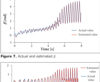
Figure 7. Actual and estimated β.
Figure 5. Effectiveness of pitch control.
Figure 9. Actual and estimated p.
SIMULATION 2
To verify the estimate efectiveness of Lipschitz adaptive observer, let us consider F1= 100 and F2= 200; the state variables for the missile in the free movement are estimated, as shown in Figs. 7 to 10. Simulation results show that state observer can estimate the state variables and unknown parameters quickly and accurately.
Another simulation is performed to verify the performance of the improved TLC method. In addition, structural damage for missiles oten happens suddenly, and it is supposed that a in of the missile is suddenly damaged on 5s ater the beginning of the simulation. he damage efectiveness is F1= 100 and F2= 200. At the same time, the actual value of aerodynamic
parameters is reduced 25% compared to the estimated value, and the simulation results are shown in Figs. 11 to 14.
he speciic command for βc in yaw channel andαc in pitch
channel is a step response signal, and the speciic command for
pc in roll channel is a constant. hese three commands are all
passed through a low-pass ilter 5s/(s + 5). In the igures, the
expected attitudes which are named “command” are marked
Figure 13. Effectiveness of roll control.
0
Time [s]
α
[rad]
0
0 2 4 6 8 10
0.12
0.08 0.06 0.04 0.02 0.1
TLC
TLC+adaptive compensation Command
Time [s]
β
[rad]
0
0 2 4 6 8 10
0.01 0.02 0.03 0.04 0.05 0.06
TLC
TLC+adaptive compensation Command
Time [s]
Roll rate [rad/s]
0
0 2 4 6 8 10
20
0 10
5 15
TLC
TLC+adaptive compensation Command
Time [s]
10 8
6 4
2 0
M
c
[deg]
-10 -5 0
5 δy
δz δr
Figure 12. Effectiveness of pitch control.
Figure 11. Effectiveness of yaw control. Figure 14. Rudder delection angles for three-channel
control in “TLC + adaptive compensation”.
control performance in three channels and enhances the robustness of the system. The missile system can converge to the expected state of motion more accurately and quickly with strong external interference. The adaptive decoupling control solves the cross coupling in three channels. The rudder deflection angles of TLC method are lead to saturation when control system diverges, and then TLC method becomes invalid. Compared to TLC, the rudder deflection angles of improved TLC are easy to achieve without saturation Figure 10. Actual and estimated F.
Time [s]
-50 0
0 2 4 6 8 10 12
50 100 150 200 250
Estimated value for F1
Estimated value for F2
Actual value for F1
Actual value for F2
Estimation for
F1
and
F2
phenomenon, and this means that the improved TLC method is physically realizable.
CONCLUSIONS
Simulation results demonstrate that improved TLC is more efective than classic TLC method, and the proposed improved TLC method exhibits a good performance in the track ability, robustness and adaptability.
REFERENCES
Ananthkrishnan N, Raisinghani SC (1992) Steady and quasisteady resonant lock-in of inned projectiles. J Spacecraft Rockets 29(5):692-696. doi: 10.2514/3.11512
Bevacqua T, Best E, Huizenga A, Cooper D, Zhu JJ (2004) Improved trajectory linearization light controller for reusable launch vehicles. Proceedings of the 42nd AIAA Aerospace Sciences Meeting and Exhibit; Reno, USA.
Djellal S, Ouibrahim A (2008) Aerodynamic performances of battle-damaged and repaired wings of an aircraft model. J Aircraft 45(6):2009-2023.
Harris J, Slegers N (2009) Performance of a ire-and-forget anti-tank missile with a damaged wing. Math Comput Model 50(1-2):292-305. doi: 10.1016/j.mcm.2009.02.009
Liu Y, Wu X, Zhu JJ, Lew J (2003) Omni-directional mobile robot controller design by trajectory linearization. Proceedings of the 2003 American Control Conference; Denver, USA.
Mickle MC, Zhu JJ (2001) Skid to turn control of the APKWS missile using trajectory linearization technique. Proceedings of the 2001 American Control Conference; Arlington, USA.
Mikhail AG (1998) Fin damage and mass offset for kinetic energy projectile spin/pitch lock-in. J Spacecraft Rockets 35(3):287-295. doi: 10.2514/2.3353
Morote J (2007) Analytic model of catastrophic yaw. J Spacecraft Rockets 44(5):1029-1037. doi: 10.2514/1.29858
Morote J, García-Ybarra PL, Castillo JL (2013) Large amplitude oscillations of cruciform tailed missiles. Part 1: catastrophic yaw fundamental analysis. Aero Sci Tech 25(1):145-151. doi: 10.1016/ j.ast.2012.01.002
Murphy CH (1963) Free light motion of symmetric missiles. BRL Report No. 1216. Aberdeen Proving Ground: U. S. Army Ballistic Research Laboratory. AD 442757.
Murphy CH (1989) Some special cases of spin-yaw lock-in. J Guid Control Dynam 12(6):771-776. doi: 10.2514/3.20480
Nguyen N, Krishnakumar K, Kaneshige J (2006) Dynamics and adaptive control for stability recovery of damaged asymmetric aircraft. Proceedings of the AIAA Guidance, Navigation, and Control Conference and Exhibit; Keystone, USA.
Pourgholi M, Majd VJ (2011) A nonlinear adaptive resilient observer design for a class of Lipschitz systems using LMI. Circ Syst Signal Process 30(6):1401-1415. doi: 10.1007/s00034-011-9320-y
Rajagopal K, Balakrishnan SN, Nguyen N, Krishnakumar K (2010) Robust adaptive control of a structurally damaged aircraft. Proceedings of the AIAA Guidance, Navigation, and Control Conference; Toronto, Canada.
Rajamani R (1998) Observers for Lipschitz nonlinear systems. IEEE Trans Automat Contr 43(3):397-401. doi: 10.1109/9.661604
Render PM, De Silva S, Walton A, Mani M (2007) Experimental investigation into the aerodynamics of battle damaged airfoils. J Aircraft 44(2):539-549. doi: 10.2514/1.24144
Render PM, Samaad-Suhaeb M, Yang Z, Mani M (2009) Aerodynamics of battle-damaged inite-aspect-ratio wings. J Aircraft 46(3):997-1004. doi: 10.2514/1.39839
Su XL, Yu JQ, Wang YF, Wang LL (2013) Moving mass actuated reentry vehicle control based on trajectory linearization. International Journal of Aeronautical and Space Sciences 14(3):247-255. doi: 10.5139/UASS.2013.14.3.247
Sun H, Yu J, Zhang S (2015) Bifurcation analysis of the asymmetric rolling missiles. Proc IME G J Aero Eng 26(9):1-2. doi: 10.1177/0954410015606941
Tanrkulu O (1999) Limit cycle and chaotic behavior in persistent resonance of unguided missiles. J Spacecraft Rockets 36(6):859-865. doi: 10.2514/2.3504
Yang I, Kim D, Lee D (2012) A light control strategy using robust dynamic inversion based on sliding mode control. Proceedings of the AIAA Guidance, Navigation, and Control Conference; Minneapolis, USA.
Zemouche A, Boutayeb M (2013) On LMI conditions to design observers for Lipschitz nonlinear systems. Automatica 49(2):585-591. doi: 10.1016/j.automatica.2012.11.029
Zhu JJ, Huizenga AB (2004) A type two linearization controller for a resuable launch vehicle — a singular perturbation approach. Proceedings of the AIAA Atmospheric Flight Mechanics Conference and Exhibit; Providence, USA.