Computer Modeling of a Spinal Reflex Circuit
Bruno L. Dalcin1, Frederico Alan Cruz2, C´elia Martins Cortez2, and Emmanuel P. L. Passos3 1Depto de Fisiologia, Universidade Federal do Rio de Janeiro, Rua Frei Caneca, 94, 20211-170, Rio de Janeiro, RJ
2Depto de Ciˆencias Fisiol´ogicas, Universidade do Estado do Rio de Janeiro,
Av. Prof. Manuel de Abreu, 444, 20551-170, Rio de Janeiro, RJ and
3Depto de Engenharia El´etrica, Pontif´ıcia Universidade Cat´olica do Rio de Janeiro, R. Marquˆes de S˜ao Vicente, 225, Rio de Janeiro, RJ
Received on 14 November, 2004. Revised version received on 13 September, 2005
We used a set of properties of the interactions among the spinal neurons in order to develop a computer model for a spinal reflex circuit. The model equations take into account the synaptic characteristics of the somatodendritic membrane of neurons in a morphofunctional unity of the spinal reflex activity. This model is based on the idea that the responses of spinal alpha-motoneurons to a sensorial stimulation can be modulated by the serial activation of a motor command chain. We developed a Fortran program for simulating a physiological situation. The results are discussed in terms of available experimental data for the motoneuron firing rate.
I. INTRODUCTION
Mathematical modeling has been widely used in biologi-cal and biomedibiologi-cal sciences [1,2]. Computer modeling tech-niques in neuroscience have been used to study neurophysio-logic circuits [3,4], leading to the investigation of mechanisms involved with the control of the locomotion system. Several models have been proposed to explain these mechanisms [5], and each one of them has contributed in different ways to the understanding of several aspects of the basic biology and function of the nervous system [6].
The modeling of neurophysiological circuits may involve the application of artificial neural network techniques [7]. However, the computer modeling of these circuits frequently requires information on certain physiological or anatomical characteristics of the nervous system which are not accessi-ble to direct measurements [Prentice et al. 2001]. There-fore, works of computer simulation are often based on sub-jective data from the literature [9]. In fact, more precise val-ues of some characteristic parameters of biomembranes and neuronal interactions are not easily available in the literature [10], and we may be forced to use theoretical model estimates for these values [11, 12, 13]. In spite of the problems related to data deficiency, system engineering has contributed to es-tablishing theoretical models and to applying functional con-cepts of the nervous system at several levels of physiologic complexity [13,14]. Important applications are related to the development of motor and sensorial neuroprothesis, including the simulation of biological circuits with increasing degrees of complexity and automation [6,15]. However, additional and more detailed studies are still required to overcome the defi-ciency of quantitative data related to neuronal interactions.
In this paper, we present a detailed description of a model for the spinal reflex circuit, taking into account the synaptic characteristics of the somatodendritic membrane of neurons in a morphofunctional unity of spinal reflex activity. We de-velop a Fortran 77 based program in order to simulate a phys-iological situation. The results are discussed on the basis of experimental data for the motoneuron firing rate.
II. BASIC MORPHOPHYSIOLOLOGY OF THE SPINAL
REFLEX
There are two general kinds of tissues in the central ner-vous system (CNS), gray matter and white matter. In the gray matter there are nerve cell bodies, dendrites covered with synapses, and axons. Neurons in gray matter organize either as surface layers named cortex or as inner neuron clusters, which are named nuclei. The white matter is basically formed by bundles of axons (or nervous fibers). Its whitish look is due the sheath of myelin involving the axons. The spinal cord gray matter is the integrative area for the spinal reflexes and other motor functions. Sensory signals enter the spinal cord through the sensory nerve roots. They have two different destinations, (a) the gray matter of the spinal cord, which is the terminal of some sensory fibers or their collaterals, and (b) the higher levels of the nervous system, reaching the supra-segmental ar-eas. The brain is considered to be the supra-segmental ner-vous system, while the spinal cord and the brain stem form the segmental nervous system [16,17].
In the spinal cord gray matter there are sensory neurons, an-terior motor neurons (AMN) and interneurons (IN).AMNsgre located in the ventral horns of the cord gray matter, and their axons leave the cord via ventral roots and innervate skeletal muscles. There are two types of AMNs, the alpha motor neu-rons (αMN) and the gamma motor neurons (γMN). OneαMN single nervous fiber innervates from three to several hundred skeletal muscle fibers. One nervous fiber and its muscle fibers are collectively called the motor unit. Individual muscles are composed of numerousmotor units. Fibers ofγMN innervate special skeletal muscle fibers calledintrafusal fibers, which are part of the sensory receptor calledmuscle spindle[16,18]. TheINs are very small, more numerous than αMNs and highly excitable. TheINs are widely interconnected among them, and many of them directly innervate the AMN. Inter-connections amongINs andAMNs are responsible for many of the integrative functions of the spinal cord. Most of the sig-nals from the spinal nerves or sigsig-nals from the brain are trans-mitted first through INs, and then reach theAMNs [19,20].
motor control originate from several brain stem areas. A basic reflex circuit starts from a type Ia nerve fiber origi-nating in a muscle receptor and entering the dorsal root of the spinal cord [21]. Then, one branch of this sensory fiber con-nects directly withαMN, which sends nerve fibers back to the same muscle. It is thus a monosynaptic reflex circuit, which presents almost no delay between spinal input and output sig-nals after excitation of the receptor [22].
Multisynaptic reflex circuits involved in pathways fromIN toαMN include Renshaw cells (RSC). They are interneurons located in the ventral horn of the spinal cord, in close associ-ation with theαMNs[23]. Collateral branches from theαMN axon are connected to the adjacent RSC. They transmit in-hibitory signals to the nextαMN, and the stimulation of each αMNtends to inhibit the surroundingαMN. For a large num-ber of synapses in the multisynaptic pathways, there will be a longer delay between spinal input and output signals, because of the period of time required for completing all of the synap-tic events. This synapsynap-tic delay is usually of about 0.5 ms [16]. Spinal reflex responses modulated by hierarchical motor control are attributed to serial activation of a motor command chain [24]. After the connection in the cord gray matter, the sensory fiber collaterals proceed to higher segmental levels and supra-segmental areas.
III. THE MODEL AND THE METHOD
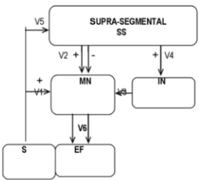
A schematic representation of the neural circuit model for the spinal reflex circuit is shown in Fig. 1. As illustrated in this figure, the signals generated in elementSgo directly to ele-mentMNthrough V1, and also proceed to higher levels of the nervous system through V5. Higher levels (supra-segmental areas) of the central nervous system are represented as ele-mentSS. After signal processing inSS, the outputs follow two distinct descending pathways, V2 and V4, which terminate at elementsMN andIN,respectively. ElementIN has an in-hibitory action on elementMN, and modulates its firing rate. After input processing,MN sends outputs to element EF via V6. The circuit elements and their basic equations are de-scribed as follows.
Element S represents the sensory receptor. The S output denotes action potentials (AP) generated from transduction of stimuli; they are represented by Dirac delta functions [25,26]. TheAPfrequency (Soutput) is related the stimulus intensity, so
S(t) = n
∑
i=1δ(t−ti), (1)
whereδ(t) is a Dirac delta function andtidenotes the occur-rence of theithAPat the sensory element. The interval be-tween successiveAPs is a random Gaussian process (truncated
FIG. 1: Schematic representation of the neural circuit as a model representative of a spinal reflex circuit:S= sensorial receptor;SS = supra-segmental area + motor structures of brain stem; V2 and V4 =SS outputs; IN = interneurons pool;MN=α-motoneurons; V1 =
MNinput fromR; V5 =MN input fromSS; V3 = input fromIN; V5 =MNoutput;EF= contractile element. The signal (+) refers to excitatory synapses and (-) to inhibitory synapses.
Element SS represents a pool of twenty neurons
distrib-uted throughout several areas of the supra-segmental and brain stem, and their axons terminate directly on spinal neurons. Ten of the twentySSneurons are directly connected to the el-ementINand the other ten are connected to the elementMN. Each neuron fiber makes ten excitatory synapses with the ele-mentMNor with the elementIN, i.e., elementSSmakes one hundred connections with the elementMN and one hundred connections withIN.
Element IN represents a pool of ten interneurons located
in the gray matter of the spinal cord. The interneurons nor-mally receive the excitatory outputs of sensory and motor ar-eas located in the supra-segmental and segmental levels. Each interneuron of the elementINmakes ten inhibitory synapses with the elementMN,and its output signals are able to mod-ulate the firingMN frequency. As already mentioned above, each fiber from elementSSmakes ten excitatory synapses with elementIN.
Element MNrepresents a motoneuron located in the
ven-tral horn of the cord gray matter. The motoneuron and all of its associated muscle fibers collectively form a motor unit. El-ementMNis able to integrate the signals from elements S,IN andSS. The inputs from elementsS andSSproduce excita-tory effects onMN, while inputs fromINgenerate inhibitory effects.
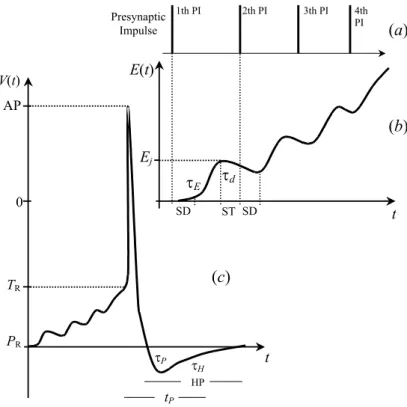
FIG. 2: (a) Schematic representation of a sequence of four presynaptic impulses (PIs) in the jth synapse, (b) the increase of the excitatory synaptic effect, E(t), after each PI. SD is the synaptic delay between each PI and the beginning of the excitatory postsynaptic potential (Ej). It
increases exponentially along 1 ms, according to the first term of Eq.2, and decays during a “silent time” (ST), according to the second term of the same equation. (c) Schematic representation of the increase ofV(t)until the PA firing, according to Eqs. 4.PRis the rest potential,τPis
the time constant at the hyperpolarization period (HP) afterAPfiring,TRis the threshold potential at rest,τHis the decay constant at relative
refractory period, andtpis the absolute refractory period.
E(t) = n
∑
j wSEjEj
q
∑
i=1exp[−(t−ti)/τE]− r
∑
k=1(k=i)exp[−(t−tk)/τd]
j
, (2)
whereEjis the characteristic amplitude of the excitatory post-synaptic potential (EPSP), n is the full amount of synapses, wSE j is the characteristic synaptic weight of the jth synapse, andtidenotes the time of arrival of ith presynaptic AP plus synaptic delay. Note that, after the arrival of the impulse in the terminals of the presynaptic fiber, there is a synaptic de-lay after which time the postsynaptic potential (PSP) begins to appear;tkdenotes the time of absence of a presynaptic
im-pulse since the last presynaptic imim-pulse. The number of input synapses is represented byq, andris the total time of absence of presynaptic impulses;τEis the time constant andτdis the decay constant. Figs. 2a and 2b show a schematic represen-tation of a time series of E(t) and the generator presynaptic impulses.
The inhibitory effect on elementMNis represented by
I(t) = n
∑
j wSIjIj
p
∑
i=1exp[−(t−ti)/τI]− s
∑
k=1(k=i)exp[−(t−tk)/τd]
j
, (3)
synap-the total number of synaptic inputs from elementIN. The total time of absence of presynaptic impulses is denoted bys, and τIis a time constant.
Element EFrepresents the contractile elements responding
to signals fromMN.
As we can see in Eqs. 2 and 3, our model exhibits two characteristic types of qualitative synaptic behavior, temporal and spatial summations. Successive postsynaptic potentials of a rapidly occurring presynaptic are summed, which is is calledtemporal summation. Spatial summationresults from the summation of postsynaptic effects generated by simulta-neously discharging presynaptic terminals.
Eq. 2 illustrates the temporal and spatial summations of ex-citatory effects on a neuron, and Eq. 3 shows temporal and spatial summations of inhibitory effects. In these equations, the first exponential refers to the arrival of the presynaptic impulses, which is related to the time constant of the rising phase and the time-to-peak of thePSP. The second exponen-tial refers to thePSPdecay during the intervals between suc-cessive presynaptic impulses. We assumed that postsynaptic membranes become highly permeable during 1 ms (τ=1.3), and that the produced postsynaptic effects persist for 8 ms, falling exponentially along this time interval (see Fig. 2b).
We consider that anAPin the postsynaptic neuron is a prod-uct of a response to a superthreshold stimulation, but a single impulse reaching the presynaptic terminal is assumed to be a subthreshold stimulus. It is known that the neurotransmitter substance released by a single presynaptic terminal is able to generate an excitatory postsynaptic potential no larger than 1 mV, but a potential of 15 to 20 mV is required for the synaptic firing. However, as a terminal fires, the released neurotrans-mitter substance opens the membrane channels for 1 ms or so. Since the postsynaptic potential lasts up to 15 ms, a sec-ond opening of the same channel can increase the postsynap-tic potential to a still larger level [16,17]. So, the intrasomal potential of postsynaptic neurons becomes about 1 mV more positive for each added excitatory discharge, the firing thresh-old is reached, and an AP is generated on the postsynaptic neuron axon.
As simultaneous inhibitory and excitatory postsynaptic po-tentials produced by widely distributed terminals can sum-mate, MN fires when a sufficiently large depolarizing effect is provided at the input, and the plasmatic membrane poten-tial, V(t), becomes larger than the threshold potential T(t). In our model, these potentials are given by
V(t) =PR+ (Po−PR)exp[−(t−tp)/τP] +E(t) +I(t) (a) T(t) =To+ (To−TR)exp[−(t−tp)/τH] (b)
(4) wherePRis a resting potential,Pois the synaptic reversal po-tential,τPis the time constant at the hyperpolarization period after theAPfiring,TRis the threshold potential at resting,To is the threshold afterAP,τH is the decay constant at relative refractory period, anttpis the absolute refractory period. In Fig. 2c, we give a schematic representation of V(t).
dynamics of V(t) is still described by Eq. 4 (a).
Equations 4(a) and 4(b) describe the temporal dynamics of a plasmatic membrane potential of a postsynaptic neuron. Eq. 4 (a)refers to the change in amplitude of the membrane poten-tial resulting from the sum of inhibitory and excitatory effects, taking into account the influence of the absolute refractory pe-riod and the time constant after the hyperpolarization pepe-riod. Eq. 4 (b)refers to the temporal dynamics of the threshold potential due to eachAPfired in a postsynaptic neuron, con-sidering the absolute refractory period and the decay constant at relative refractory period.
Equations (2) to (4) allow the inclusion in this problem of the following synaptic characteristics.
Thefacilitationmechanism is associated with Eq. 2, since it contains the spatial summation. According to this mecha-nism, signals from the supra-segmental areas can facilitate the elementMN,so that they are able to respond quickly and eas-ily to signals arriving from elementS. In this case, the mem-brane potential is closer than normally to the firing threshold, but not yet to the firing level. So, a signal enteringMNfrom some other via can then excite it very easily.
As we can note in Eq. 3, the inhibitory effect produced by INonMN is assumed to be dependent on time. It increases with the activity expansion from the supra-segmental via. This increase reproduces the natural increase during theadaptive processalong the uninterrupted activation of the spinal reflex circuit.
The synaptic after-firing mechanism [16] can also be taken into account in this problem, since Eqs. 4 consider the after-firing changes in the membrane potential and after-firing thresh-old, as well as the relative refractory period. This mechanism makes it possible that a single instantaneous input provokes a sustained signal output during some milliseconds, which might result in repetitive firings. If one impulse arrives at the presynaptic terminal in this period of time, its postsynaptic ef-fect can be summed in order to keep the output signal, and the firing threshold can be reached again.
All simulation programs were written inFortran 77(Visual Fortran 95 for Windows), compiled and run on PC DOS com-puters. In those programs, we used numerical values for the parameters found in the literature (Table 1). Some of those values were obtained from experimental studies. The main program accepts input parameters from disk files and writes output data to a disk file. This program was able to estimate postsynaptic effects using Eqs. 2 and 3 at each millisecond, and then using the results in Eqs. 4. Time series ofMN mem-brane potentials resulting from simultaneous activities of the excitatory and inhibitory synapses were estimated during 200 ms.
Table 1. Some values for neurobiologic parameters
Parameter (symbol) Value Ref.
MN rest potential(PR) – 65 mV [16]
MN reversal potential(Po) + 10 mV [35,34]
Time constant of IPSP (τI) 1.0 ms [18]
Threshold potential at rest(TR) – 40 mV [36]
Threshold potential after firing(To) – 10 mV [36]
Decay time constant of refractory period (τH) 1.2 ms [36]
IPSP(I) – 72mV [34]
AP time interval 1.3 ms [34]
this facilitation period can last from a few seconds in some neurons to several hours in others [16]. In our program, we implemented the occurrence of thepost-tetanic facilitation af-ter 1 s of a rapidly repetitive series of impulses (frequency higher than 250 Hz) onMN andIN, assuming a reduction in τPof 5% after eachMNfiring.
As in all excitatory synapses, in our problem there can be afatigueof the synaptic transmission if the neuron is repet-itively excited at a rapid rate. In this case, the neuron firing number becomes progressively smaller with the increasing of the excitation time. Usually, the fatigue occurs in a few sec-onds to a few minutes. Our system was programmed to fa-tigue 3 seconds after repetitive excitation (frequency higher than 250 Hz), because the threshold potential HR begins to decrease 0.02% after eachMNfiring.
IV. RESULTS AND DISCUSSION
The model that we are proposing incorporates the excita-tory and inhibiexcita-tory properties of the somatodendritic mem-brane of neurons in a morphofunctional unity of the spinal reflex activity. This model takes into account a set of known synaptic characteristics, including certain mechanisms of tem-poral and spatial bioelectric responses, as the synaptic after firing, the adaptive process, the facilitation, the post-tetanic facilitation, and the synaptic fatigue. The physiological prop-erties of digitalling and autopropagability of theAPare rep-resented by Dirac delta functions. Routines to calculate post-synaptic effects for the circuit elements were established from Eqs. 2 and 3, using Eqs. 4a and 4b for estimating the time se-ries of the membrane potential. The summation of inhibitory and excitatory effects was performed by a suitable computer program.
Random depolarizing signals from elementsSandSSare as-sumed to reach elementMN through 10 and 100 synapses, respectively. ElementSalso sends outputs to elementSS, but we did not model the processing within this element. How-ever, we assumed that elementSScan send a random output to elementsMNandIN,but eachSSoutput only reaches both elements, MN andIN,15 ms after theSfiring. So, the im-pulsesSStoMNare the impulses whichSShas received from S, with a delay of 15 ms. This was assumed on the basis of the time interval required for one signal to travel via theS -SSspinal pathway to reachMN [16]. The elementMN also receives inhibitory signals fromINthrough 100 synaptic con-nections.
The output of elementIN,which isgenerated by processing random signals (200Hz) fromSSduring 200 ms, can be seen in Fig. 3. The excitatory synaptic weight (wSE j)onINis 0.9, the synaptic delay is 0.6 ms, and the other parameter values are given in Table 1. Fig. 3 shows the result of this processing as a random collection ofAPs with a mean frequency of 45 Hz. This result is in overall agreement with the literature. The measured values in interneurons of decerebrate cats vary from 20 to 110 Hz [26]. According to Cleland and Rymer [27], certain interneurons within the cord gray matter have a vari-able and elevated spontaneous activity with mean frequency 30.3(±20.1) Hz, and sensory-evoked responses larger than 400 Hz.
FIG. 3: Output of the elementINgenerated by the processing (Eqs. 2 to 4) of random inputs (200 Hz) from elementSSduring 200 ms. We assumed a rest potential of -70 mV, and a synaptic delay of 0.5 ms. EPSP=-68mV,IPSP=-72mV,wSE j =0.9,tp=5 ms,τP=1.2 ms,
τH=1.3 ms (the other parameter values are given in Table 1).
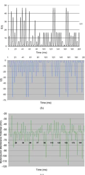
Figs. 4a and 4b illustrate the registered synaptic activities whenMN issimultaneously stimulated by all the other circuit elements during 200 ms. In these figures, we see the depolar-izing (Fig. 4a) and hyperpolardepolar-izing (Fig. 4b) effects coming from the application of equations 2 and 3, respectively.
(b)
(c)
FIG. 4: Addition of (a) depolarizing and (b) hyperpolazing synaptic effects (Eqs. 2 and 3) onMNfor inputs coming from elements S,
INandSS. (c) Estimated power spectrum of theMNmembrane po-tential resulting from simultaneously activities of the excitatory and inhibitory synapses during 200 ms. We assumed a rest membrane potential of –70 mV (represented in the vertical axis by zero), and a synaptic delay of 0.5 ms. EPSP=-68mV,IPSP=-72mV,wSE j=0.9, wSI j=0.6 (the other parameter values are given in Table 1).
which corresponds to a decrease in the membrane potential from rest to -128.99 mV. We usedwSI j=0.5 forMN.
Figure 4c shows the time series of membrane potentials re-sulting from simultaneous activities of the excitatory and in-hibitory synapses, during 200 ms, on elementMN.This graph represents the variation in membrane potential of elementMN due to algebraic summation of depolarizing and
hyperpolar-the membrane potential estimated from Eqs. 4 (a) and (b) dur-ing 200 ms is -36.8 mV; the minimum value is about –118.0 mV.
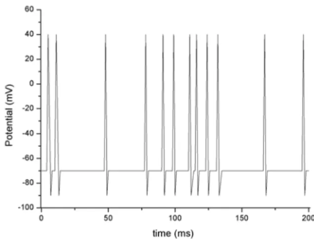
An irregularMN firing of mean frequency 120 Hz can be observed in Fig. 5. The threshold potential was –40 mV (see Table 1). The time interval to the first firing is about 2 ms after the arrival of the firstAPin the presynaptic membrane. The next twoAPs appear only after 8.0 and 24 ms, respectively. These results are on the physiological scale. It is known that the maximum firing frequencies ofMN are usually smaller than 100 Hz, but they may be up to 300 Hz at the beginning of an afferent stimulus [17,26,29-31].
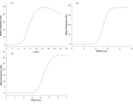
Figures 6a, 6b and 6c show the behavior of the average fir-ing rate ofMN as a function of the time constant (τE), the excitatory (Ej) and inhibitory (Ij) postsynaptic potentials for a given value of the input rate (100 Hz), according to Eqs. 2 and 3. In each of these graphs, we observe a minimum value at which the elementMNbegins firing. The frequency increases linearly until reaching a maximum value, and then it tends to remain constant or to decrease, which determines the value of the parameter related to the synaptic fatigue for that input frequency.
FIG. 5: MN output derived from the sum of synaptic events for a random circuit stimulation (200 Hz) during 200 ms. MN receives simultaneous inputs fromS,SSandIN. We assumed a rest membrane potential of -70 mV, and a synaptic delay of 0.5 ms. EPSP=-68mV,
IPSP=-72mV,wSE j=0.9,wSI j=0.6,tp=5 ms,τP=1.2 ms,τH=1.3 ms
(the other parameter values are given in Table 1). The firstMNfiring occurs between 1.0 ms and 2.0 ms, and the second firing takes place after 9.0 ms. The mean frequency of synaptic events is 200 Hz.
phe-FIG. 6: Behavior of the average firing rate of MN as a function of (a)the time constant (τE), (b)excitatory (Ej), and (c)inhibitory (Ij)
postsynaptic potentials, according to Eqs. 2 and 3 (the input rate is 100 Hz,wSE j=0.9,wSI j=0.6,τE=10 ms; the other parameter values are
given in Table 1).
nomena.
In summary, our spinal reflex model produced results on a physiological scale. The model equations were able to de-scribe the behavior of each circuit component. They were based on the synaptic transmission characteristics, including the typical parameters. The simulation environment can be easily expanded to include another neuronal geometry and additional membrane channels, as well as new cell and fiber populations. More realistic numerical values could have been used in the model equations if we were able to obtain more detailed data for the peripheral receptors, motoneurons and interneurons. We were unable to find experimental references
for some of the parameters.
The data obtained in this work are being used in an ongo-ing study about backpropagation to a neural network based on a control modeling of spinal reflex patterns. In addition, the model will be expanded in order to include an explicit repre-sentation of the cortical neurons and other spinal afferences. Also, we are proposing a model a coupled oscillators to sim-ulate the dynamical behavior of the sensoriomotor cortex and other structures within the suprasegmental nervous system.
This work was supported by Fundac¸˜ao de Amparo `a Pesquisa do Estado do Rio de Janeiro, FAPERJ.
[1] M. G. Velarde, V. I. Nekorkin, V. B. Kazantsev, V. I. Makarenko, and R. Llin´as, Neural Networks15, 5 (2002). [2] P. J. G. Lisboa, Neural Networks15, 11 (2002).
[3] J. Peng, H. Qiao, and Z. Xu, Neural Networks15, 95 (2002). [4] C. Robert, C. Guilpin, and A. Limoge, J. Neurosci. Methods
79, 187 (1998).
[5] S. Rossignol, and R. Dubuc, Curr. Opin. Neurobiol. 4, 894 (1994)
[6] N. Donaldson, D. Rushton, and T. Tromans, Lancet 350, 711 (1997).
[7] R. E. Bekka, S. Boudaoud, and D. Chikouche, J. Neurosc. Meth.116, 89 (2002).
[8] S. D. Prentice, A. E. Patla, and D. A. Stacey, J. Electromyogr. Kinesiol.11, 19 (2001).
[9] S. D. Prentice, A. E. Patla, and D. A. Stacey, Exp Brain Res.
123, 474 (1998).
[10] C. Cortez and P. M. Bisch, Braz. J. Phys.26,604 (1996). [11] K. M. Soares and C. Cortez, J. Theor. Biol.169, 169 (1999). [12] F. A. O. Cruz, F. S. D. S. Vilhena, and C. Cortez, Braz. J. Phys.
30, 403 (2000).
[13] E. Bizzi, F. A. Mussa-Ivaldi, and S. Giszter, Science253, 287 (1991).
[14] A. Lansner and ¨O. Ekeberg, Curr. Opin. Neurobiol. 4, 903 (1994).
[15] R. T. Lauer, P. H. Peckham, and K. L. Kilgore, Neuroreport.10, 1767 (1999).
[16] A. C. Guyton and J. E. Hall,Human physiology and mecha-nisms of disease. 6thedition. W. B. Saunders Co. Philadelphia,
USA (1997).
(1971).
[19] W. A. Friedman, G. W. Sypert, J. B. Munson, and J. W. Flesh-man, J. Neurophysiol. 46, 1349 (1981).
[20] R. W. Ryall, M. F. Piercey, and C. Polosa, J. Neurophysiol.34, 700 (1971).
[21] R. E. Burke, B. Walmsley, and J. A. Hodgson, Brain Res. 160, 347 (1979).
[22] T. Chang, S. J. Schiff, T. Sauer, J. P. Gossard, and R.E. Burke, Biophys. J.67, 671 (1994).
[23] R. B. Stein and M. N. Oguztoreli, Neuroscience11, 231 (1984). [24] R. J. Nelson,Curr. Opin. Neurobiol.6, 801 (1996).
[25] V. S. F´enelon, B. Casasnovas, J. Simmers, and P. Meyrand, Curr. Opin. Neurol.8, 705 (1998).
[26] D. P. Bashor, Biol. Cybern. 78, 147 (1998).
[27] C. L. Cleland, and W. Z. Rymer, J. Neurophysiol. 69, 1181 (1993).
[29] R. K. D. B. Powers and M. D. Binder, J. Neurophysiol.75, 367 (1996).
[30] A. J. McComas, M. Mirsky, F. Velho, and A. Struppler, J. Neu-rol. Neurosci. Psychiatry, 42, 1091 (1979).
[31] W. R. Schlue, D. W. Richter, K-H. Mauritz, and A.C. Nacimiento, J. Neurophysiol. 37, 303 (1974).
[32] M. Andreasen, J.D.C. Lambert, J. Physiol.507, 441 (1998). [33] O. Sacchi, M. L. Rossi, R. Canella, and R. Fesce, J.
Neurophys-iol.79, 727 (1998).
[34] P. Kudela, P. J. Franaszczuk, and G. K. Bergey, Biol. Cybern.
77, 71 (1997).
[35] E. F. Barrett, J. N. Barrett, and W. E. Crill, J. Physiol. 304, 251 (1980).