ISSN 0104-6632 Printed in Brazil
www.abeq.org.br/bjche
Vol. 26, No. 02, pp. 407 - 414, April - June, 2009
Brazilian Journal
of Chemical
Engineering
SECOND-LAW ANALYSIS OF LAMINAR
NON-NEWTONIAN GRAVITY-DRIVEN LIQUID FILM
ALONG AN INCLINED HEATED PLATE WITH
VISCOUS DISSIPATION EFFECT
S. Saouli
1*and S. Aïboud-Saouli
21
Faculty of Sciences and Engineer’s Sciences, Phone: +213 (0) 72 84 24 01, Fax: +213 (0) 29 71 19 75, University Kasdi Merbah, 30 000, Ouargla, Algeria.
E-mail: [email protected]
2 Professional Training Institute, Saïd Otba, 30 000, Ouargla, Algeria.
E-mail: [email protected]
(Submitted: February 1, 2007 ; Accepted: June 12, 2007)
Abstract - A second-law analysis of a gravity-driven film of non-Newtonian fluid along an inclined heated plate is
investigated. The flow is assumed to be steady, laminar and fully-developed. The upper surface of the liquid film is considered to be free and adiabatic. The effect of heat generation by viscous dissipation is included. Velocity, temperature and entropy generation profiles are presented. The effects of the flow behaviour index, the Brinkman number and the group parameter on velocity, temperature and entropy generation number are discussed. The results show that velocity profile depends largely on the flow behaviour index. They are flat near the free surface for pseudoplastic fluids and linear for dilatant fluids. Temperature profiles are higher for higher flow behaviour index and Brinkman number. The entropy generation number increases with Brinkman number and the group parameter because of the heat generated by the viscous dissipation effect. For pseudoplastic fluids, the irreversibility is dominated by heat transfer, whereas, for dilatant fluids, irreversibility due to fluid friction is more dominant.
Keywords: Entropy generation; Non-Newtonian; Power-law fluids; Second-law; Viscous dissipation.
INTRODUCTION
Fluid flow and heat transfer characteristics in falling liquid films along inclined plates at different boundary conditions are one of the fundamental researches in engineering. Studies of simpler systems are useful to understand some important features of complex combinations forming processes in many fields of science and technology. These basic geometries are common in many engineering applications as sole units or as a global entity.
Entropy generation is closely associated with thermodynamic irreversibility, which is encountered in all heat transfer processes. Different sources are responsible for the generation of entropy, such as
circular duct. A comparative study of the entropy generation rate inside ducts of different shapes (circular, triangular, square etc.) and the determination of the optimum duct shape subject to isothermal boundary condition for laminar flow were carried out by Sahin (1998). Narusawa (1998) gave an analytical and numerical analysis of the second-law for flow and heat transfer inside a rectangular duct. In a more recent paper, Mahmud and Fraser (2003) applied the second-law analysis to fundamental convective heat transfer problems. They analysed the second-law characteristics of heat transfer and fluid flow due to forced convection of steady-laminar flow of incompressible fluid inside a channel with circular cross-section and channel made of two parallel plates. Different problems are discussed with their entropy generation profiles and heat transfer irreversibility characteristics. In each case, analytical expressions for entropy generation number and Bejan number are derived in dimensionless form using velocity and temperature profiles. In another paper, Mahmud and Fraser (2002) investigated analytically the first and second law characteristics of fluid flow and heat transfer inside a channel having two parallel plates with finite gap between them. Fully developed forced convection is considered. Fluid is assumed to be non-Newtonian and follow the power law model. Analytical expressions for dimensionless entropy generation number, irreversibility distribution ratio and Bejan number are determined as a function of dimensionless distance, Peclet number, Eckert number, Prandtl number, dimensionless temperature difference and fluid behaviour index. Spatial distribution of entropy generation number, irreversibility ratio and Bejan number are presented graphically. The same authors (Mahmud and Fraser, 2002) reported, in terms of local and average entropy generation, the inherent irreversibility of fluid flow
and heat transfer for non-Newtonian fluids in a pipe and a channel made of two parallel plates. They assumed the flow to be fully developed with a uniform heat flux at the duct wall. They applied the first and the second laws of thermodynamics to develop expressions for dimensionless entropy generation number, irreversibility ratio and Bejan number as function of geometric, fluid and flow parameters.
However, in these analyses concerning non-Newtonian fluids, the influence of viscous dissipation is omitted. The present paper aims at analysing the mechanism of entropy generation in a gravity-driven laminar film of a non-Newtonian fluid along an inclined heated plate, taking care of the presence of viscous dissipation effect.
ANALYSIS
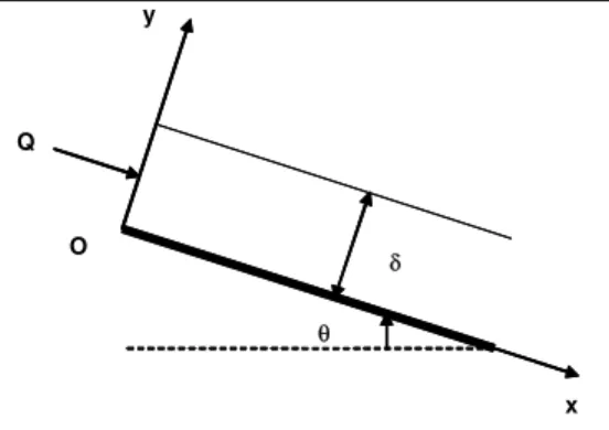
The physical configuration is illustrated schematically in Fig. 1. The falling liquid, driven by gravity, flows a down flat heated plate inclined at an angle θ to the horizontal. It is assumed that the flow is laminar and fully developed. The liquid surface is waveless, free and adiabatic.
The non-Newtonian fluid used in this study is the power-law model (Ostwald-de Waele fluid). Such fluids are characterized by the following rheological law:
( )
nu y K
y ∂
⎛ ⎞
τ = ⎜ ∂ ⎟
⎝ ⎠ (1) where n is the flow behaviour index and K is the consistency of the fluid. A fluid is pseudoplastic when n≺1, Newtonian when n=1, and dilatant when n 1 .
x y
δ O
Q
θ
x y
δ O
Q
θ
Neglecting the inertia terms in the momentum equation compared with the body force term, the momentum equation reduces to the following form:
( )
nu y
K g sin 0
y y
∂
⎛ ⎞
∂ + ρ θ =
⎜ ⎟
∂ ⎝ ∂ ⎠ (2) The associated boundary conditions are:
No-slip condition
( )
u 0 =0 (3a)
Free surface condition
( )
u 0 y ∂ δ
=
∂ (3b)
The velocity distribution is obtained by integrating Eq. (2) and using the boundary conditions given by Eqs. (3a) and (3b). It may be written:
( )
n 1 n m
y
u y u 1 1
+
⎡ ⎤
⎛ ⎞
⎢ ⎥
= ⎢ − −⎜ ⎟ ⎥ δ
⎝ ⎠
⎢ ⎥
⎣ ⎦
(4)
where umis the velocity at the free surface:
1 n 1 n
n m
n g sin
u
n 1 K
+
ρ θ
⎛ ⎞
= ⎜ ⎟ δ
+ ⎝ ⎠ (5) The mass flow rate of the liquid is:
( )
0
Q u y dy
δ
= ρ
∫
(6)from which the liquid film thickness may be computed:
m
2n 1 Q
n 1 u
+ δ =
+ ρ (7)
Combining Eqs. (5) and (7), we obtain an expression for the liquid film thickness:
(
)
{
}
{
(
)
}
n 2n 1( )1 n n 1
2n 1 n Q gsin K
+ +
⎧ ⎫
δ =⎨ ⎡⎣ + ⎤⎦ ρ θ ⎬
⎩ ⎭ (8)
The governing energy equation is:
( ) ( )
2( )
2 n 1P
T x, y T x, y K u(y)
u y a
x y C y
+
∂ = ∂ ⎛∂ ⎞
⎜ ⎟
∂ ∂ ρ ⎝ ∂ ⎠ (9)
subject to the following boundary conditions:
Inlet condition
( )
0T 0, y =T (10a)
Wall heat flux
( )
T x,0 q y ∂
−λ =
∂ (10b)
Adiabatic surface
( )
T x, 0 y
∂ δ
=
∂ (10c)
The equation of energy can be transformed into a dimensionless form by introducing the following dimensionless variables:
2 m
ax X
u =
δ , y Y=
δ, ΔT= qδ λ (11)
( )
( )
m
u y U Y
u
= ,
(
X, Y)
T x, y( )
T0 T−
Θ =
Δ (12) The transformation yields:
(
)
2(
)
n 12
X, Y X, Y U(Y)
U(Y) Br
X Y Y
+
∂Θ =∂ Θ + ⎛∂ ⎞
⎜ ⎟
∂ ∂ ⎝ ∂ ⎠ (13)
Br =
n 1 n 1
n 1 2n 1
2n 1 KQ
n 1 q
+ +
+ +
+
⎛ ⎞
⎜ + ⎟ ρ δ
⎝ ⎠
is the Brinkman number.
The transformed boundary conditions are:
(
0, Y)
0Θ = (14a)
(
X,0)
1 Y
∂Θ
= −
∂ (14b)
( )
X,10 Y ∂Θ
=
∂ (14c) To get a solution of Eq. (13), a separation of variables solution is assumed in the following form (Arpaci and Larsen, 1984):
(
X, Y)
1( ) ( )
X 2 Y 1( )
X 2( )
YThe first term on the right-hand side of Eq. (15) is significant for decaying initial transition and entrance effects, the second term is significant for axial temperature rise due to accumulated wall heat flux and the third term is significant for transverse temperature variation due to wall heat flux into fluid. Neglecting the entrance effect and assuming that the system already passed the decaying initial transition, then the first term at the right-hand side of Eq. (15) will disappear (Mahmud and Fraser 2002; 2003). Combination of Eq. (15) and Eq. (13) leaves two separate ordinary equations connected by a scalar constant α:
( )
1 X
X ∂Θ
= α
∂ (16)
( )
(
)
(
)
2 n 1
2
n 2
n 1 n 1
n
Y
1 1 Y
Y
n 1
Br 1 Y n
+
+ +
∂ Θ ⎡ ⎤
= α − −⎢ ⎥
∂ ⎣ ⎦ + ⎛ ⎞ −⎜ ⎟ − ⎝ ⎠ (17)
Integrating Eqs. (16) and (17) and applying boundary conditions described in Eq. (14), the expression for the dimensionless temperature is obtained in the following form:
(
)
(
)(
) (
)
(
)(
) (
)
2
2 3n 1
n
n 1 2
3n 1
n 1
X, Y X Y
2
n
1 Y 2n 1 3n 1
n 1
n Br
n
1 Y C Y C
2n 1 3n 1
+
+
+
α
Θ = α +
α − − + + + ⎛ ⎞ ⎜ ⎟ ⎝ ⎠ − − + + + + (18)
where α and C are: 1
n 1
n 1
2n n Br 1
n n 1 + + ⎛ ⎞ + ⎜ ⎟ + ⎝ ⎠ α =
+ , C1= −α (19)
To obtain the constant of integration C , we use the mean bulk temperature, defined as:
( )
(
)
1(
)
b
A 0
1
X X, Y dA X, Y dY
A
Θ =
∫
Θ = Θ∫
(20)Since Eq. (14a) requires Θb
( )
0 =0, the constant of integration is:(
)(
)(
)
(
)(
)(
)
3 n 1 3 n C2n 1 3n 1 4n 1
n 1
n Br
n
2n 1 3n 1 4n 1 3
+ α = + + + + + ⎛ ⎞
⎜ ⎟ α
⎝ ⎠ +
+ + +
(21)
ENTROPY GENERATION RATE
The entropy generation rate according to Mahmud and Fraser (2002) is:
( )
( )
( )
2 2 G 2 0 n 1 0T x, y T x, y
S x y T u y K T y + ⎡⎛∂ ⎞ ⎛∂ ⎞ ⎤
λ ⎢ ⎥
= ⎜ ⎟ +⎜ ⎟ ∂ ∂ ⎢⎝ ⎠ ⎝ ⎠ ⎥ ⎣ ⎦ ∂ ⎛ ⎞ + ⎜ ⎟ ∂ ⎝ ⎠ (22)
The entropy generation number may be defined as:
2 0
S 2 G
T
N S
q λ
= (23)
Using the definitions of dimensionless velocity and temperature, the following expression is obtained for the entropy generation number:
(
)
(
)
( )
2 2
S 2
n 1
C Y F
X, Y X, Y
1 N X Y Pe U Y Br
N N N
Y + ∂Θ ∂Θ ⎛ ⎞ ⎛ ⎞ = ⎜ ⎟ +⎜ ⎟ ∂ ∂ ⎝ ⎠ ⎝ ⎠ ∂ ⎛ ⎞ + ⎜ ⎟ = + +
Ω⎝ ∂ ⎠
(24)
In the above equation, Pe =
P
2n 1 QC n 1
+
⎛ ⎞ λ
⎜ + ⎟
⎝ ⎠ is the
RESULTS AND DISCUSSION
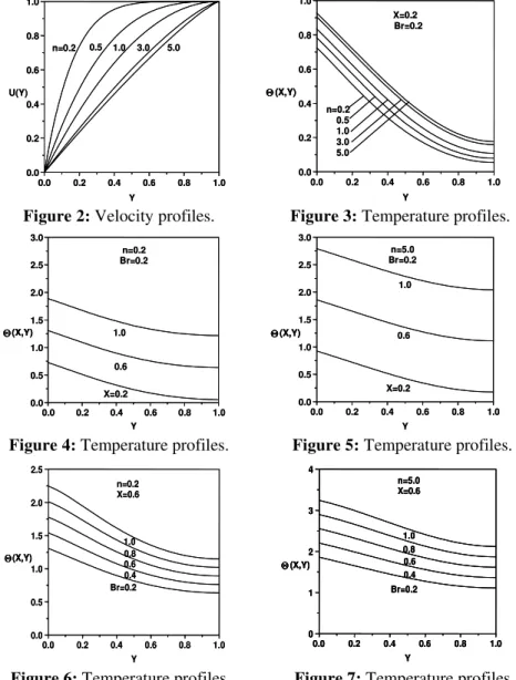
Dimensionless axial velocity profiles are plotted as a function of dimensionless transverse distance in Fig. 2 for five different values of the flow behaviour index. For pseudoplastic fluids ( n≺1), velocity profiles remain flat near the free surface and this flatness decreases with the increase of the low behaviour index. For Newtonian fluids ( n=1), the dimensionless axial velocity shows the usual semi-parabolic shape. For dilatant fluids ( n 1 ), velocity profiles approach a linear shape as the flow behaviour index increases.
Dimensionless temperature profiles are plotted in Fig. 3 for the same range of the flow behaviour index. For the present boundary condition, temperature is maximum at the wall where a heat flux is imposed and minimum at the free surface whatever the value of the flow behaviour index is. For a particular transverse distance, the temperature is higher for a higher flow
behaviour index. This means that dilatant fluids heat more easily than pseudoplastic fluids.
The axial variations of the dimensionless temperature profiles are plotted in Figs. 4 and 5 for pseudoplastic fluids ( n=0.2) and dilatant fluids (n=5.0). In all cases, the temperature increases in the axial direction because of the continuous heating of the wall.
The effect of the Brinkman number on the temperature is illustrated in Figs. 6 and 7 for pseudoplastic fluids ( n=0.2) and for dilatant fluids ( n=5.0). The temperature increases as the Brinkman number increases either for pseudoplastic fluids or dilatant fluids. As the Brinkman number, which determines the relative importance between viscous dissipation effects and fluid conduction, increases, more heat is generated by the viscous dissipation effect in the fluid. This generated heat by viscous dissipation effect results in higher temperature profiles.
0.0 0.2 0.4 0.6 0.8 1.0
0.0 0.2 0.4 0.6 0.8 1.0 5.0 3.0 1.0 0.5 n=0.2 U(Y) Y
0.0 0.2 0.4 0.6 0.8 1.0
0.0 0.2 0.4 0.6 0.8 1.0 5.0 3.0 1.0 0.5 n=0.2 U(Y) Y
0.0 0.2 0.4 0.6 0.8 1.0
0.0 0.2 0.4 0.6 0.8 1.0 n=0.2 0.5 1.0 3.0 5.0 X=0.2 Br=0.2 Θ(X,Y) Y
0.0 0.2 0.4 0.6 0.8 1.0
0.0 0.2 0.4 0.6 0.8 1.0 n=0.2 0.5 1.0 3.0 5.0 X=0.2 Br=0.2 Θ(X,Y) Θ(X,Y) Y
Figure 2: Velocity profiles. Figure 3: Temperature profiles.
0.0 0.2 0.4 0.6 0.8 1.0
0.0 0.5 1.0 1.5 2.0 2.5 3.0 1.0 0.6 X=0.2 n=0.2 Br=0.2 Θ(X,Y) Y
0.0 0.2 0.4 0.6 0.8 1.0
0.0 0.5 1.0 1.5 2.0 2.5 3.0 1.0 0.6 X=0.2 n=0.2 Br=0.2 Θ(X,Y) Θ(X,Y) Y
0.0 0.2 0.4 0.6 0.8 1.0
0.0 0.5 1.0 1.5 2.0 2.5 3.0 1.0 0.6 X=0.2 n=5.0 Br=0.2 Θ(X,Y) Y
0.0 0.2 0.4 0.6 0.8 1.0
0.0 0.5 1.0 1.5 2.0 2.5 3.0 1.0 0.6 X=0.2 n=5.0 Br=0.2 Θ(X,Y) Θ(X,Y) Y
Figure 4: Temperature profiles. Figure 5: Temperature profiles.
0.0 0.2 0.4 0.6 0.8 1.0
0.0 0.5 1.0 1.5 2.0 2.5 1.0 0.8 0.6 0.4 Br=0.2 n=0.2 X=0.6 Θ(X,Y) Y
0.0 0.2 0.4 0.6 0.8 1.0
0.0 0.5 1.0 1.5 2.0 2.5 1.0 0.8 0.6 0.4 Br=0.2 n=0.2 X=0.6 Θ(X,Y) Θ(X,Y) Y
0.0 0.2 0.4 0.6 0.8 1.0
0 1 2 3 4 1.0 0.8 0.6 0.4 Br=0.2 n=5.0 X=0.6 Θ(X,Y) Y
0.0 0.2 0.4 0.6 0.8 1.0
0 1 2 3 4 1.0 0.8 0.6 0.4 Br=0.2 n=5.0 X=0.6 Θ(X,Y) Y
0.0 0.2 0.4 0.6 0.8 1.0
0 1 2 3 4 1.0 0.8 0.6 0.4 Br=0.2 n=5.0 X=0.6 Θ(X,Y) Θ(X,Y) Y
In Figs. 8 and 9, the entropy generation number is plotted as a function of the dimensionless transverse distance for different values of the Brinkman number for pseudoplastic fluids ( n=0.2) and dilatant fluids ( n=5.0). In all cases, no entropy is generated at the free surface where both velocity and temperature are maximum (or minimum), which cause zero velocity and temperature gradients, leaving no contribution to the entropy generation number (second and third term of Eq. (24)).
For a particular transverse distance, the magnitude of the entropy generation number is higher for higher Brinkman numbers because of the heat generated by the viscous dissipation effect. In the case of pseudoplastic fluids ( n=0.2), the entropy generation number decreases along the transverse distance to reach zero at the free surface. This can be explained by the fact that, for pseudoplastic fluids, the velocity profile is flat near the free surface leaving no contribution of fluid friction on entropy generation. Therefore, the irreversibility is mainly dominated by heat transfer. For dilatant fluids ( n=5.0), for a particular transverse distance, the entropy generation number shows a maximum near the wall as the Brinkman number increases. According to Fig. 2, the velocity profile is nearly linear (high velocity gradient);, this means that the contribution of fluid friction to
entropy generation number increases. Thus, for dilatant fluids, the irreversibility is dominated by fluid friction.
Figs. 10 and 11 show the distribution of the entropy generation number as function of the transverse distance at different values of group parameter ranging from 0.2 to 1. No entropy generates at the free surface where both velocity and temperature are maximum (or minimum) which cause zero velocity and temperature gradients, leaving no contribution to the entropy generation number (second and third term of Eq. (24)) for all values of group parameter. For a particular transverse distance, the entropy generation number is higher for higher group parameter. For pseudoplastic fluids ( n=0.2), the entropy generation number decreases with the transverse distance and does not show maxima except for the case where (BrΩ =−1 0.2). This means that the irreversibility is dominated by heat transfer and the wall acts as a strong concentrator of irreversibility. For dilatant fluids ( n=5.0), the contribution of fluid friction on entropy generation number is dominant, the entropy generation number shows maxima near the wall. Comparing the magnitude of entropy generation number for pseudoplastic and dilatant fluids, the results show that irreversibility is more pronounced for pseudoplastic fluids.
0.0 0.2 0.4 0.6 0.8 1.0
0 2 4 6 8 10
Br=0.2 0.4 0.6 0.8 1.0 n=0.2
Pe=100
N
S
Y
BrΩ-1 =1.0
0.0 0.2 0.4 0.6 0.8 1.0
0 2 4 6 8 10
Br=0.2 0.4 0.6 0.8 1.0 n=0.2
Pe=100
N
S
Y
BrΩ-1 =1.0
0.0 0.2 0.4 0.6 0.8 1.0
0 1 2 3 4 5
Br=0.2 0.4 0.6 0.8 1.0 n=5.0
BrΩ-1=1.0
Pe=100
N
S
Y
0.0 0.2 0.4 0.6 0.8 1.0
0 1 2 3 4 5
Br=0.2 0.4 0.6 0.8 1.0 n=5.0
BrΩ-1=1.0
Pe=100
N
S
Y
Figure 8: Entropy generation number. Figure 9: Entropy generation number.
0.0 0.2 0.4 0.6 0.8 1.0
0 2 4 6 8 10
0.8 0.6 0.4 0.2 n=0.2 Br=1.0 Pe=100
N
S
Y BrΩ-1=1.0
0.0 0.2 0.4 0.6 0.8 1.0
0 2 4 6 8 10
0.8 0.6 0.4 0.2 n=0.2 Br=1.0 Pe=100
N
S
Y BrΩ-1=1.0
0.0 0.2 0.4 0.6 0.8 1.0
0 1 2 3 4 5
BrΩ-1=1.0 0.8 0.6 0.4 0.2 n=5.0
Br=1.0 Pe=100
NS
Y
0.0 0.2 0.4 0.6 0.8 1.0
0 1 2 3 4 5
BrΩ-1=1.0 0.8 0.6 0.4 0.2 n=5.0
Br=1.0 Pe=100
NS
Y
CONCLUSION
The second-law analysis is applied to a gravity-driven, laminar, non-Newtonian liquid film with free and adiabatic surface. The heat generation by viscous dissipation is included in the analysis. Analytical expressions for velocity and temperature within the film are provided as a function of the flow behaviour index and the Brinkman number. The effects of the flow behaviour index, the Brinkman number and the group parameter on entropy generation number are discussed. From the results the following conclusions could be drawn:
a) Velocity profile depends largely on the flow behaviour index. They are flat near the free surface for pseudoplastic fluids and linear for dilatant fluids. b) Temperature profiles shift to higher temperatures with an increasing flow behaviour index.
c) For pseudoplastic fluids and dilatant fluids, temperature profiles increase with the axial distance because of the continuous heating of the wall.
d) As the Brinkman number increases, the temperature profile increases because of the heat generated by the viscous dissipation effect.
e) The entropy generation number increases with the Brinkman number and the group parameter. This is due to the heat generated by the viscous dissipation effect.
f) For pseudoplastic fluids, the irreversibility is dominated by heat transfer, whereas for dilatant fluids, irreversibility due to fluid friction is more dominant.
Nevertheless, it is necessary to carry out further analyses and calculations for different geometries and non-Newtonian fluids other than those obeying the power-law model.
NOMENCLATURE
a thermal diffusivity m2/s
A area m2
Br Brinkman number (-)
C constant of integration (-)
1
C constant of integration (-)
P
C specific heat J/kg.K
g gravitational acceleration m/s2
K consistency of the fluid Pa.sn
n flow behaviour index (-)
C
N entropy generation, axial conduction
(-)
F
N entropy generation, fluid friction
(-)
S
N entropy generation number, (-)
total
Y
N entropy generation number, transverse conduction
(-)
Pe Peclet number (-)
q wall heat flux W/m2
Q liquid mass flow rate kg/m.s
G
S entropy generation rate W/m3.K
T temperature K
u axial velocity m/s
U dimensionless axial velocity (-)
x axial distance m
X dimensionless axial distance (-)
y transverse distance m
Y dimensionless
transversetance
(-)
Greek Symbols
α scalar constant (-)
δ thickness of the liquid film m
T
Δ reference temperature difference
K
λ thermal conductivity W/m.K
θ inclination angle rad
Θ dimensionless temperature (-)
Ω dimensionless temperature difference
(-)
ρ density of the fluid kg/m3
τ shear stress Pa
Subscripts
b bulk value
m maximum value
0 inlet value, reference value
REFERENCES
Arpaci, V. S., Larsen, P. S., Convection heat Transfer. Prentice-Hill. Engelwood Cliffs, New Jersey (1984).
Bejan, A., Second-law analysis in heat transfer and thermal design, Adv. Heat Transfer, 15, pp. 1-58 (1982).
Bejan, A., Entropy generation minimization. CRC Press, Boca Raton, New York (1996).
Bejan, A., A study of entropy generation in fundamental convective heat transfer. J. Heat Transfer, 101, pp. 718-725 (1979).
Mahmud, S., Fraser, R. A., Thermodynamic analysis of flow and heat transfer inside channel with two parallel plates. Exergy, 2, pp. 140-146 (2002).
Mahmud S., Fraser, R. A., 2002, Inherent irreversibility of channel and pipe flows for non-Newtonian fluids. Int. Comm. Heat Mass Transfer, 29, pp. 577-587 (2002).
Narusawa, U., The second-law analysis of mixed convection in rectangular ducts. Heat Mass Transfer, 37, pp. 197-203 (1998).
Sahin, A. Z., Second law analysis of laminar viscous
flow through a duct subjected to constant wall temperature. J. Heat Transfer, 120, pp. 76-83 (1998).
Sahin, A. Z., Effect of variable viscosity on the entropy generation and pumping power in a laminar fluid flow through a duct subjected to constant heat flux. Heat Mass Transfer, 35, pp. 499-506 (1999).