Abstract
This study conducted high-velocity penetration experiments using conventional ogive-nose, double-ogive-nose, and grooved-tapered projectiles of approximately 2.5 kg and initial velocities between 1000 and 1360 m/s to penetrate or perforate concrete targets with unconfined compressive strengths of nominally 40MPa. The pene-tration performance data of these three types of projectiles with two different types of materials (i.e., AerMet100 and DT300) were obtained. The crater depth model considering both the projectile mass and the initial velocity was proposed based on the test results and a theoretical analysis. The penetration ability and the trajecto-ry stability of these three projectile types were compared and ana-lyzed accordingly. The results showed that, under these experi-mental conditions, the effects of these two different kinds of projec-tile materials on the penetration depth and mass erosion rate of projectile were not obvious. The existing models could not reflect the crater depths for projectiles of greater weights or higher veloci-ties, whereas the new model established in this study was reliable. The double-ogive-nose has a certain effect of drag reduction. Thus, the double-ogive-nose projectile has a higher penetration ability than the conventional ogive-nose projectile. Meanwhile, the grooved-tapered projectile has a better trajectory stability, because the convex parts of tapered shank generated the restoring moment to stabilize the trajectory.
Keywords
High-velocity penetration; Double-ogive-nose; Grooved-tapered; Crater depth; Penetration ability; Trajectory stability.
High-velocity Penetration of Concrete Targets with Three
Types of Projectiles: Experiments and Analysis
1 INTRODUCTION
Earth-penetrating weapons (EPW) are an effective means of attacking hard and deeply buried tar-gets. The penetration performance of an EPW can be commonly enhanced by increasing the impact
Shuang Zhang a HaiJun Wu a, XinXin Zhang a JianCheng Liu a FengLei Huang. a
a State Key Laboratory of Explosion
Science and Technology, Beijing Insti-tute of Technology, Beijing 100081, PR China
Corresponding author: wuhj@bit.edu.cn
http://dx.doi.org/10.1590/1679-78253753
velocity, improving the projectile material, and optimizing the projectile structure. Therefore, per-forming an experimental study is necessary to compare and analyze the effects of these three cou-pling factors on the penetration ability, and the trajectory and structural stabilities of projectiles.
Forrestal et al. (1994, 1996, 2003), Frew et al. (1998), Wu et al. (2012), and Shan et al. (2015, 2014) conducted a series of penetration experiments, but the projectiles they used usually had lower velocities or lower weights (gram scale). Therefore, more studies on the concrete target penetration or perforation tests using projectiles with weights of several kilograms and velocities of at least 1000 m/s are still needed. Wu and Huang et al. (2012) performed penetration tests with a wide range of initial velocities using five types of projectile materials. Their results showed that the crater depth is approximately four times of the projectile diameter d which is two times larger than that predicted by the widely used model proposed by Forrestal et al. (1994), when the projectile initial velocity is approximately 1200 m/s. They also found that the projectile material is of great significance in en-suring structural strength, reducing mass erosion, and increasing penetration ability. In addition, He and Chen et al. (2014) pointed out that the difference in the strength and the hardness of the pro-jectile material might change the erosion mechanism. AerMet100 and DT300 are representatives of high-strength alloy steel, and comparatively studying the effect of these two types of materials on the penetration performance is necessary.
The projectile structure is the main factor affecting the projectile penetration performance, in-cluding the penetration ability, and the trajectory and structural stabilities under the condition of a given quality, velocity, and material. Chai (2014) presented that the new nose shape comprising a conventional ogive-nose and a small front cylinder (nose-pin) could reduce the penetration resistance at low or medium speed and increase the penetration depth. Based on classical cavity expansion theory, Liu et al. (2015) proposed an optimal design scheme of a double-ogive-nose projectile with a smaller penetration resistance by researching the influence of the nose shape on the inertial re-sistance term under a high-velocity penetration. Meanwhile, Zhang (2016) studied the mechanical model, dynamic structure response and trajectory stability of grooved-tapered projectiles through experiments and numerical simulations. He and Chen et al. (2016) recently experimentally studied the penetration performance and mass loss of a concept projectile for a high-speed penetration (CPHP), which is referred to herein as the grooved-tapered projectile. However, the grooved-tapered structure and the other structures lacked an intuitive comparison. Furthermore, combining the abovementioned theoretical achievements and further studying the influence of the projectile struc-ture on the penetration ability and the trajectory stability are necessary.
2 EXPERIMENTAL PROGRAM
2.1 Projectiles
Figure 1 shows the three types of projectiles, namely, the conventional ogive-nose, double-ogive-nose, and grooved-tapered projectiles. Each type had six quantities: three were made of AerMet100, while the other three were composed of DT300. A total of 18 experiments were conducted.
The double-ogive-nose projectiles were optimized according to Liu et al. (2015) and had the same mass as the conventional ogive-nose projectiles by adjusting the inner hollow parts. The grooved-tapered projectiles had conventional ogival noses and tapered shanks with six symmetrical grooves (Zhang, 2016). Table 1 shows the main parameters of these three types.
Types Mass
(kg)
Length (mm)
Diameter (mm)
Caliber radius head (CRH)
Ogive-nose 2.12 312 45 3
Double-ogive-nose 2.12 312 45 N/A
Grooved-tapered 2.75 312 45/56 3
Table 1: Main parameters of the three projectile types.
(a) Comparison of the three projectile types (b) Details of the grooved-tapered projectiles
(c) Details of the noses (d) Details of the shanks
2.2 Concrete Targets and Test Procedure
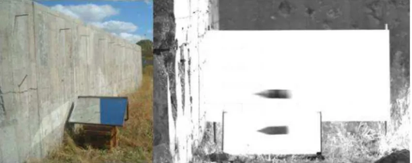
The concrete targets used in these experiments had unconfined compressive strengths of nominally 40MPa and an aggregate size of less than 20 mm. The concrete targets with 2 m thickness were casted into a line and separated by thin wooden boards, which could enhance lateral confinements and prevent the destruction of the adjacent targets. In addition, as shown in Figure 2, another line of concrete targets was casted behind the test targets to withdraw the projectiles. The gaps between the two targets could be used to measure the residual velocities of the projectiles perforating the test targets.
The 100-mm-caliber smoothbore gun and nylon sabots were used to launch the projectiles. Two high-speed digital cameras were utilized to record the attitudes and the initial and residual veloci-ties of the projectiles. The double-light path testing system in Figure 3 was used to observe the yaw angles of the projectiles. The damage situations of the targets were then photographed after the test. The penetration depths, dimensions of the front and back craters, relative positions of the impact and perforating points, and percentages of the projectile mass losses were measured.
Figure 2: Structure and layout of the concrete targets.
Figure 3: Double-light path testing system and the projectile attitude.
3 EXPERIMENT RESULTS AND ANALYSIS
Shot
number Type Material
Initial velocity
(m/s)
Pitch and yaw (degree)
Crater depth (mm)
Penetration depth (mm)
Residual velocity (m/s)
1 ON AerMet100 1073 1U, 2L 150 1610 N/A
2 ON AerMet100 1286.1 1U, 7R 210 Perforated 363.8
3 ON AerMet100 1361.7 5D, 7R 270 Perforated N/A
4 ON DT300 1083.3 1U, 5L 190 Perforated 144.4
5 ON DT300 1275 N/A 170 Perforated N/A
6 ON DT300 1257.9 0, 7R 260 Perforated 341.7
7 DON AerMet100 1020 2U, 12R 180 1680 N/A
8 DON AerMet100 1264.2 3D, 12L 200 Perforated 325.8
9 DON AerMet100 1309.6 1D, 10R 320 Perforated 459
10 DON DT300 1118.5 5D, 23R 200 1570 N/A
11 DON DT300 1270.3 2D,5L 170 1170 N/A
12 DON DT300 1327.1 0, 2L 480 Perforated 474
13 GT AerMet100 1073 2U, 5R 200 2000 0
14 GT AerMet100 1234.4 2U, 1L 200 Perforated 257.3
15 GT AerMet100 1351.7 4U, 6L N/A Non-perforated Broken
16 GT DT300 956.6 5U, 1R 170 1320 N/A
17 GT DT300 1201.8 0, 19R 200 1350 N/A
18 GT DT300 1305.3 0, 2R 210 Non-perforated Broken
Table 2: Main test results of the 18 experiments. For the type: ON=ogive-nose; DON=double-ogive-nose;
and GT=grooved-tapered. For the pitch and yaw: D=down; U=up; R=right; and L=left.
3.1 Analysis of the Experimental Phenomena
Table 2 shows an obvious trend, that is, the projectile finally perforated the test target and ob-tained a higher residual velocity with the increase of the initial velocity. In this speed range, in-creasing the projectile velocity could increase the penetration depth. As shown in Figure 4, the di-ameters of the front carters in these experiments when the projectiles impact the test targets with initial velocities of 1000–1300 m/s were approximately 800 mm. This value was much larger than that in Liu et al. (2009), where two to eight times of projectile diameters were proposed. In addition, many penetrative cracks were observed on the surface of the test targets. These radial cracks ap-peared because the huge acting force applied on the concrete around the high-velocity projectile was big enough to make the hoop stress of concrete exceed the tensile strength. Meanwhile, the diame-ters of the front cardiame-ters when the same projectiles perforated the test targets and impacted the back targets with a residual speed of 300–400 m/s were significantly reduced to approximately 200–400 mm. No crack was found, as shown in Figure 5.
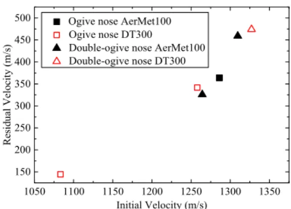
little bit better. However, as shown in Figures 7 and 8, the comparisons of the penetration abilities of the projectiles with the same structures and different materials indicated that the effects of these two types of materials on the test results were not obvious under these experimental conditions.
Figure 4: Crater under a high-velocity impact of 1083.3m/s.
Figure 5: Crater under a low-velocity
impact of 341.7m/s.
0.0 0.1 0.2 0.3 0.4 0.5 0.6 0
500 1000 1500 2000 2500
Tu
re stress
(MPa
)
Ture strain
Quasi-static compression AerMet100 Quasi-static compression DT300 Strain rate 2500/s AerMet100 Strain rate 2500/s DT300 400℃ Strain rate 2500/s AerMet100 400℃ Strain rate 2500/s DT300
1050 1100 1150 1200 1250 1300 1350 150
200 250 300 350 400 450
500 Ogive nose AerMet100 Ogive nose DT300
Double-ogive nose AerMet100 Double-ogive nose DT300
Resi
du
al
V
el
oci
ty
(m/
s)
Initial Velocity (m/s)
Figure 6: Stress–strain curves of AerMet100 and DT300. Figure 7: Comparison of the residual velocities.
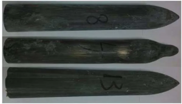
projectile was more severe in the case of the same materials and velocities. Thus, the mass loss rate of the smaller projectile was relatively higher.
900 1000 1100 1200 1300 1200
1400 1600 1800 2000
Double-ogive nose AerMet100 Double-ogive nose DT300 Grooved-Tapered AerMet100 Grooved-Tapered DT300
DOP
(mm)
Initial Velocity (m/s)
Figure 8: Comparison of the depths of penetration (DOP). Figure 9: Projectiles after the test.
3.2 Crater Depth Model Considering Both the Projectile Mass and Velocity
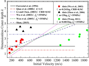
The front surface of the target will spall and form a cone-shaped crater under impact. The target crater is the initial stage of the whole penetration process, which reflects a considerable part of the penetration ability (Liu et al., 2009). The crater depths in these experiments were significantly larg-er than those proposed by Forrestal et al. (1994), which wlarg-ere widely used and known as two times of the projectile diameters d. Most of the existing crater depth models (Forrestal et al., 1994; Shan, 2015; Qian et al., 2000; Li and Chen, 2003; Wu et al., 2003; Wen et al., 2005) were presented based on the regression analysis of the experimental data. However, several times differences might be obtained when these models are used to predict under some experimental conditions because of the relative singleness of the data that they relied upon. The crater depth was expressed as k times the projectile diameter d, i.e., the dimensionless crater depth was k. As shown in Figure 10, the points were the experimental data, and the lines were the results calculated by each model. The compari-son indicated that, the experimental crater depths from Zhou et al. (2006) and Wang (2011) could not be well predicted by any existing models because of the greater weights or higher velocities of the projectiles. Therefore, establishing a new crater depth model considering both the mass and the velocity was necessary.
Data sources Mass of the
projectiles (kg)
Initial veloci-ties (m/s)
Diameters of the projec-tiles (m)
Zhou et al. (2006) 25 300–600 0.1
Wang (2011) 0.0032 1200–1700 0.007
Wu and Huang et al. (2012) 0.09, 0.1, 0.13 800–1350 0.015
Shan (2015) 0.1, 0.13 1050–1350 0.015
Wu et al. (2003) 0.241, 0.47, 1.1 150–450 0.0273, 0.0341, 0.0455
Chai (2014) 1.41 400, 600, 800 0.040
This paper 2.1 1000–1360 0.045
200 400 600 800 1000 1200 1400 1600 1800 1
2 3 4 5 6 7 8
data (Wu et al., 2003) 凚m=0.241kg, CRH=8.54凛 data (Zhou et al., 2006) 凚m=25kg, fc'=35MPa凛
data (Wang, 2011) 凚m=0.0032kg, fc'=35MPa凛
Dimension
less
Cra
ter d
epth
k
Initial Velocity (m/s)
Forrestal et al. (1994) Qian et al. (2000)凚k=1.5凛 Li and Chen, (2003)凚CRH=8.54凛 Wu et al. (2003)凚fc'=35MPa凛 Wen et al. (2005)凚fc'=35MPa凛 Shan, (2015)
Figure 10: Comparison of the existing crater depth models.
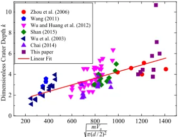
With reference to the experimental data having various projectile properties (Table 3), the rela-tionship between the ‘momentum per unit area of projectile cross section’ and the ‘dimensionless crater depth’ was plotted as a graph by ignoring the effects of the nose shape and the target strength. The data points presented a linear regularity in Figure 11. Therefore, they could be fitted linearly as follows:
2
1.08 0.003 ( /2)s
mV k
d
(1)
Notice that the dimension of Equation (1) is not unified, and correct units should be used. m is the projectile mass (kg); Vs is the initial velocity (m/s); and d is the projectile diameter (m). Thus,
the crater depth Hc (m) can be expressed as follows:
1.08 0.0034
c s
H kd d mV (2)
200 400 600 800 1000 1200 1400 0
2 4 6 8
10 Zhou et al. (2006) Wang (2011)
Wu and Huang et al. (2012) Shan (2015)
Wu et al. (2003) Chai (2014) This paper Linear Fit
D
im
en
sio
nl
ess Cra
ter D
ep
th
k
2 ( /2)mVd s
Figure 11: Relationship between the ‘momentum per unit area of projectile
cross section’ and the ‘dimensionless crater depth’.
3.3 Comparison and Analysis of the Penetration Ability
Figure 12 shows the comparison of the residual velocities of the three projectile types. The residual velocities increased with the increase of the initial velocities, and the trend was obvious. As regards the residual velocities of the projectiles with similar initial velocities and different structures, the double-ogive-nose projectiles had the strongest penetration ability, followed by the conventional ogive-nose projectiles of the same mass. Meanwhile, the grooved-tapered projectiles with a larger mass had no advantage in terms of the penetration ability.
Forrestal et al. (1994) proposed the axial resistance of the projectile in the tunnel area based on the cavity expansion theory and linearized the resistance in the crater area. Combined with the crater depth model established earlier, the expressions of the penetration resistance F are presented as follows:
0 c
Fcz z H (3a)
2 2
c c
Fa SfN V zH (3b)
where, z is the instantaneous penetration depth; c is the constant given in Forrestal et al. (1994); a is the projectile radius; S is the dimensionless coefficient used to modify the unconfined compressive strength of concrete fc; is the target density; N is the projectile nose factor; and V is the
1050 1100 1150 1200 1250 1300 1350 0 100 200 300 400 500 Ogive-nose Double-ogive-nose Grooved-tapered Re sidual V eloci ty (m/s)
Initial Velocity (m/s)
Ogive-nose calculated Double-ogive-nose calculated Ogive-nose tested Double-ogive-nose tested
0 200 400 600 800 1000 1200 1400 0 10 20 30 40 50 60 Pene tratio n De pth / d
Initial Velocity (m/s)
Figure 12: Comparison of the residual velocities of the three projectile types.
Figure 13: Relationship between the dimensionless
penetration depth and the initial velocity.
Ogive-nose Double-ogive-nose
0.0 0.5 1.0 1.5 2.0 2.5 3.0 3.5 4.0 0 10000 20000 30000 40000 50000 D ecelr ation / g
Time (ms) 0.0 0.5 1.0 1.5 2.0 2.5 3.0 3.5 0 5 10 15 20 25 30 35 40 Pe net rat ion D epth / d Time (ms) Ogive-nose Double-ogive-nose
Figure 14: Deceleration time history curves of the projectiles with an initial velocity of 1050m/s.
Figure 15: Dimensionless penetration depth time history
curves of the projectiles with an initial velocity of 1050m/s.
2 1
2 ln 1
2 c c
c
N V m
P H P H
a N Sf
(4a)
2 2
2
1 s c 2 c
c
mV H a Sf
V
m H a N
(4b)
where, Vs is the initial velocity (m/s), and V1 is the instantaneous velocity at the end of the crater.
Calculated following the method of Liu et al. (2015), the projectile nose factors N of the conven-tional ogive-nose (ON) and double-ogive-nose (DON) were 0.1076 and 0.1033, respectively. The penetration depths and the decelerations of these two types of projectiles when penetrating into semi-infinite concrete targets could be provided with = 2300 kg/m3 and fc =40MPa using
Equations (3) and (4).
related to fc and an inertial resistance related to the penetration velocity. The ratio of the inertia
resistance including N increased along with the increase of the velocity. The smaller the N, the smaller the inertia resistance, and the bigger the penetration depth. Figures 14 and 15 show the time history curves of the deceleration and dimensionless penetration depth of these two types of projectiles with the same initial velocity. The double-ogive-nose projectile has a smaller penetration resistance and a bigger penetration depth. The theoretical calculation and numerical simulation results illustrated that the double-ogive-nose projectile optimally designed by Liu et al. (2015) based on the ogive-nose projectile with CRH=5 had an obvious advantage in terms of the penetration ability. In the present study, the advantage of the double-ogive-nose projectile optimized based on the ogive-nose projectile with CRH=3 was not very obvious. However, the experimental results and the theoretical analysis still showed the effect of drag reduction of the double-ogive-nose.
In addition, the influence of the double-ogive-nose on the penetration is not featured only by the decrease of the inertial resistance. Chai (2014) previously proposed that the nose pin (i.e., the first ogive) with a smaller diameter and a certain length in the front end of the double-ogive-nose could also destroy the concrete, thereby reducing the penetration resistance of the remaining part of the projectile nose.
3.4 Comparison and Analysis of the Trajectory Stability
Figure 16 shows the tunnel shape of the grooved-tapered projectile with an initial velocity of 1073m/s. The tunnel was very straight, and the petal-shaped grooves were obvious on its surface. This image indicated that the tapered shank of the grooved-tapered projectile was always in contact with the target in the penetration process. The convex parts of the tapered shank directly extruded the concrete target, thereby generating the restoring moment to overcome the unstable lateral load and stabilize the trajectory.
Figure 16: Tunnel shape of the grooved-tapered
projectile with an initial velocity of 1073m/s.
Figure 17: Sketch of the projectile penetrating or perforating into a finite thickness target (Shan, 2015).
the cavity expansion theory and the differential area force law, as shown in Figure 17. In this meth-od, the projectile surface elements were first decentralized, as shown in Figure 18. The modified Warren’s free surface effect model (Shan, 2015; Warren et al., 2004) was used to modify the interac-tion force between the projectile and the target. The interacinterac-tion force considering the free surface effect was directly applied to the surface elements based on the projectile target separation method. The wake separation and reattachment effect (Bernard and Creighton, 1979) was considered in the calculation process. Furthermore, the two-dimensional motion control equations in Wang S. C. (2011) were used.
Zhang et al. (2016) established a dynamic spherical cavity expansion model considering both concrete compression and dilatation. They then fitted the following relationship between the dimen-sionless cavity boundary radial stress r/ fc and the dimensionless cavity expansion velocity
0
/
r
V f :
2
1 2 3
0 0
r r r
c c c
V V
a a a
f f f
(5)
where, a1, a2, and a3 are the fitting parameters that correspond to 0.9083, 2.7059, and 7.2464,
re-spectively, for the 40MPa concrete. The results of the penetration experiments using conventional ogive-nose and grooved-tapered projectiles with an initial velocity of 1250m/s and an incidence an-gle of 5° perforating the 2 m concrete target were calculated after embedding the interaction force obtained by the abovementioned cavity expansion theory into the trajectory prediction program. These experimental conditions were similar to those in test Numbers 6 and 14 herein. In addition, the tapered projectile with the same quality and size, as shown in Figure 18, was also calculated to further illustrate the advantages of the grooved-tapered projectile.
Figure 19 shows the axial velocity time history curves. The residual velocities of the conven-tional ogive-nose and grooved-tapered projectiles were 308m/s and 277m/s, which were basically equivalent to the test results obtained from test Numbers 6 and 14, respectively. Figure 20 presents the trajectories of the projectile nose tips. The calculation results of the projectile lateral displace-ment were relatively close to those determined by the relative position of the impact and perforat-ing points. Shan (2015) proved that this trajectory prediction program had a certain rationality through the comparison between calculation results and experimental data in references. Figures 19–21 can further confirm this rationality, and they showed that the trajectories of the grooved-tapered and grooved-tapered projectiles under the same initial conditions were almost coincidental. In addi-tion, the lateral displacements and the lateral decelerations were all smaller than those of the con-ventional ogive-nose projectile.
length had a similar trajectory stability, stronger penetration ability, and better structural stability, which lead to a better projectile structure design.
0 1 2 3 4
200 400 600 800 1000 1200 1400 Axia l V el oc ity (m /s) Time (ms) Ogive-nose Tapered Grooved-tapered
Figure 18: Sketch of the discrete projectiles. Figure 19: Axial velocity time history curves.
0 2 4 6 8 10 12 14 16 18 20 22 50 40 30 20 10 0 Ta rget symmetr ic axi s Target edge
Target front face
Target back face
Ve rti cal displ acement / d
Lateral displacement / d
Ogive-nose Tapered Grooved-tapered
Ogive-nose Test No.6
Grooved-tapered Test No.14
Impact point
0.0 0.5 1.0 1.5 2.0 2.5 3.0 3.5 -5000 0 5000 10000 15000 20000 Lat era l D ec ele rati on / g Time (ms) Ogive-nose Tapered Grooved-tapered
Figure 20: Trajectories of the projectile nose tips. Figure 21: Lateral deceleration time history curves.
4 CONCLUSIONS
ta-pered projectile with the same mass and projectile length. These findings can be used in the pene-tration prediction and the future projectile structure design.
Acknowledgments
This work was supported by National Natural Science Foundation of China through grant No.11390362 and No.11572048, and the Defense Industrial Technology Development Program of China through grant No.B1020132071. Many thanks to the 732nd factory of the China North In-dustries Group for their support in the experimental research.
References
Bernard, R. S., Creighton, D. C., (1979). Projectile penetration in soil and rock: analysis for non-normal impact. Technical report SL-79-15. U.S. Army Engineer Waterways Experiment Station Structures Laboratory. MS, USA: Vicksbury.
Chai, C. G., (2014). Study on the mechanism of penetration into concrete of nose headed projectile, Ph.D. Thesis (in Chinese), Beijing Institute of Technology, China.
Forrestal, M. J., Altman, B. S., Cargile, J. D., et al., (1994). An empirical equation for penetration depth of ogive-nose projectiles into concrete targets. International Journal of Impact Engineering 15(4):395-405.
Forrestal, M. J., Frew, D. J., Hanchak, S. J., et al., (1996). Penetration of grout and concrete targets with ogive-nose steel projectiles. International Journal of Impact Engineering 18(5):465-476.
Forrestal, M. J., Frew, D. J., Hickerson, J. P., et al., (2003). Penetration of concrete targets with deceleration-time measurements. International Journal of Impact Engineering 28(5):479-497.
Frew, D. J., Hanchak, S. J., Green, M. L., et al., (1998). Penetration of concrete targets with ogive-nose steel rods. International Journal of Impact Engineering 21(6):489-497.
He, L. L., Chen, X. W., Wang, Z. H., (2016). Study on the penetration performance of concept projectile for high-speed penetration (CPHP). International Journal of Impact Engineering 94:1-12.
He, L. L., Chen, X. W., Xia, Y. M., et al., (2014). Representation of nose blunting of projectile into concrete target and two reduction suggestions. International Journal of Impact Engineering 74:132-144.
Li, Q. M., Chen, X. W., (2003). Dimensionless formulae for penetration depth of concrete target impacted by a non-deformable projectile. International Journal of Impact Engineering 28(1): 93-116.
Liu, H. P., Gao, S. Q., Lei, J., et al., (2009). Phase analysis on crater-forming of projectile penetrating into concrete target. Binggong Xuebao/acta Armamentarii 30:52-56. (in Chinese)
Liu, J. C., Pi A. G., Huang, F. L., (2015). Penetration performance of double-ogive-nose projectiles. International Journal of Impact Engineering 84:13-23.
Qian, L. X., Yang, Y. B., Liu, T., (2000). A semi-analytical model for truncated-ogive-nose projectiles penetration into semi-infinite concrete targets. International Journal of Impact Engineering 24(9): 947-955.
Shan, Y., (2015). Investigation on the erosion and motion of the projectile non-normal penetrating into concrete, Ph.D. Thesis (in Chinese), Beijing Institute of Technology, China.
Shan, Y., Huang, F. L., Wu, H.J., (2014). The influence of projectile material on mass abrasion of high-velocity penetrator. Proceedings of the 28th International Symposium on Ballistics, Atlanta.
Wang, K. H., (2011). Study of high velocity projectile penetrating concrete target, Ph.D. Thesis (in Chinese), Beijing Institute of Technology, China.
Warren, T. L., Hanchak, S. J., Poormon, K. L., (2004). Penetration of limestone targets by ogive-nosed VAR 4340 steel projectiles at oblique angles: experiments and simulations. International Journal of Impact Engineering 30(10):1307-1331.
Wen, Z. P., Wang, Y. X., Lv, B. M., et al., (2005). Calculation method on crater depth of projectile penetrating into concrete vertically. Journal of Changzhou Institute of Technology 18(s1):82-84.
Wu, H. J., (2013). Mechanics performance analysis of AerMet100 and DT300. Technical report. Beijing Institute of Technology, China. (in Chinese)
Wu, H. J., Huang, F. L., Wang, Y. N., et al., (2012). Experimental investigation on projectile nose eroding effect of high-velocity penetration into concrete. Binggong Xuebao/acta Armamentarii 33(1):48-55. (in Chinese)
Wu, H.J., Wang, Y. N., Huang, F. L., (2012). Penetration concrete targets experiments with non-ideal & high veloci-ty between 800 and 1100m/s. International Journal of Modern Physics B 22(9n11), 1087-1093.
Wu, X. Y., Li, Y. C., He, X., et al., (2003). On mechanism of slender projectile penetrating into concrete. Chinese Journal of Rock Mechanics and Engineering 22(11):1817-1822.
Zhang, X. X., (2016). The response characteristic of high-speed grooved tapered projectile penetrating into the con-crete, Ph.D. Thesis (in Chinese), Beijing Institute of Technology, China.
Zhang, X. X., Yan, L., Wu, H. J., Huang, F. L., (2016). A note on the dynamic spherical cavity expansion of con-crete with shear dilatancy . Binggong Xuebao/acta Armamentarii 37(1):42-49. (in Chinese)