Abstract
Bolted structures are widely utilized in industrial structures and equipment due to the numerous advantages they possess. However, the use of bolts in these structures by itself can cause considerable flaws or damages. One of the major reasons of flaw in such struc-tures is looseness. Since the looseness is initiated with a reduction in the axial force, measurement and estimation of this force can contribute to a healthy performance of the structure. The methods used to measure axial force of bolts are divided into two: those which measure or estimate the force directly and those which, by controlling physical parameters, do this indirectly. Ba- sed on this categorization, this paper examines over 16 methods used for eval-uation of axial force of bolted structures, and presents their theo-retical bases, drawbacks and advantages, with the litera- ture on each method being discussed separately. Finally, the met- hods are compared and the most important criteria in selecting the methods are introduced.
Keywords
Bolted Structures, Looseness Detection, Bolt Preload, Fault Detec-tion, Ultrasonics.
A Review Paper on Looseness Detection
Methods in Bolted Structures
1 INTRODUCTION
Bolts are temporary connections and due to this feature, they are often used in most mechanical structures. Bolts possess several significantly favorable features like the ability to bear relatively heavy loads, low costs, easy installation and implementation and acceptable reliability. Besides the positive features, bolted joints are subject to flaw, which can consequently result in damages to the construction or equipment. The causes for such flaws include stress concentration, crack, corrosion and looseness. Looseness is a process initiated with slipping. Slipping, which can be caused by ex-ternal forces or vibration, first occurs in bolt threads and plates and leads to slipping of the plates
Seyed Majid Yadavar Nikravesh a, * Masoud Goudarzi b
a Associate Professor, Mechanics and
Energy Faculty, Shahid Beheshti Univer-sity, Tehran, Iran.
b PhD Candidate, Mechanics and Energy
Faculty, Shahid Beheshti University, Tehran, Iran. ([email protected])
* Corresponding author
http://dx.doi.org/10.1590/1679-78254231
and bolt heads, resulting in micro-vibrations of the plates (Bickford, 2007; Caccese, et al., 2004; Wang, et al., 2013; Hess, 1988).
Another problem with monitoring bolted joins in terms of looseness is assuring the appropriate-ness of the axial force applied to the bolt. As inadequacy of this force can cause damages to the structure due to looseness, excessive axial force could also impose stresses on the bolt, which in turn lowers its efficiency. Therefore, monitoring this axial force is a significant factor in detection and investigation of looseness of bolted joints (J. Bickford, 2008). To measure axial force and its ade-quacy or inadeade-quacy, numerous methods exist, which could be classified under various groups based on the available literature. The basis for such classifications could include directness or indirectness of measurement, activeness or passiveness or even usage for online or offline condition monitoring. In this paper, the classification will be based on the directness or indirectness of the measurement method. In the former case, there are methods which measure axial force or bolt torque directly, while in the latter group, there exist methods which rely on physical phenomena and estimate looseness of joints using indirect strategies like parameters apart from axial force or screw torque. To do so, 16 disparate methods will be investigated and their usage instructions, drawbacks and advantages will be elucidated, together with the relevant literature.
2 DIRECT MEASUREMENT METHODS
Two important parameters in detection and assessment of looseness of bolted structures are the applied torque and the axial force on the bolts. Thus, to monitor the conditions of the joints, direct measurement of these parameters is a principal approach among the primary methods proposed and developed for such purposes. Although most of these measurement methods are old-fashioned and they are only mentioned in standard statements–and not in recent academic papers–they are still widely used in various industries (Goodier, 1945). As of now, various methods have been proposed for measurement of axial force, torque, torque control and rotation angle of screws and bolts. In the following section, the most important and practical direct axial force measurement methods will be presented.
2.1 Direct Tension Indicator Method
Figure 1: Direct Tension Indicators (Bickford, 2007).
2.2 Strain Gauges
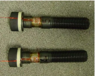
Strain gauges or force sensors which are often electronic or piezoelectric are generally used in two ways: either as a washer or integrated bolts. Washer-like strain gauges are flexible rings which are placed between a given plate and bolt and measure the amount of pressure applied by the bolt. Once the torque is applied on the bolt, the axial force to the joint increases and the washer measures the applied force continuously. While these washers have acceptable accuracy, they are comparatively expensive and are mainly used for experiments and special cases. With the develop-ments in technology, an ever-increasing number of manufacturers are producing integrated strain gauges and bolts (Figure 2). This, not only, results in elimination of washers and a reduction in the volume of joints, but it also reduces the force error by 1 to 2 per cent. Furthermore, in cases where several strain gauges are used in different points, bending and torsion can be detected as well (Goodier, 1945; Bickford, 2007).
Another way is to use strain gauges to monitor length variations in bolts in order to determine the existing axial force in the joint. In this method, by installing strain gauges in both sides of a given bolt, the length variations in the bolt can be monitored and consequently its axial force could be controlled. The main drawback of this method is that because of the materials used in produc-tion of bolts, their strain is usually marginal and slight changes cannot be measured with high accu-racy. Besides, this method can only be used when both sides of the bolt are accessible. In addition to this method, other methods such as those which use ultrasonic waves have been proposed and used for a more accurate monitoring of bolt length fluctuations, which will be delineated below (Goodier, 1945; Bickford, 2008).
2.3 Torque Control
One of the most primary methods to control and investigate looseness is the torque wrench tech-nique. In this technique, using torque-meters, the inspector examines the torque of a bolt at deter-mined time intervals and assures that it has not declined. While this method might seem old-fashioned, it is still used in many and various industries. Studies have shown that despite the sim-plicity and low cost of the method, only 10 to 15 per cent of the applied torque is used to spin the bolt, and 85 to 90 per cent is wasted to resist the existing friction, which results in significantly lower accuracy and up to 50 per cent of error. Although the use of lubricants can reduce the friction to a great extent, it can mean excessively more axial force, which may cause additional stresses on the structure. Apart from the mentioned drawbacks, this method does not allow for online monitor-ing of the structure, and its performance is dependent upon the inspector’s performance, regular investigations and human errors, as well (J. Bickford, 2008; Goodier, 1945; Joshi & Pathare, 1984).
3 INDIRECT MEASUREMENT METHODS
As was mentioned above, despite their simplicity, direct methods have low rate of accuracy and they do not allow for online monitoring of bolted structures, and this has pushed detection and investigation methods toward indirect methods. In fact, in these methods, the effect of axial force reduction on a physical parameter is examined and using the variations and fluctuations of the pa-rameter, the inadequacy of the axial force is estimated. In the following section, the most common types of indirect methods for detection and evaluation of looseness of bolted structures will be de-scribed, together with their merits and demerits (Joshi & Pathare, 1984).
3.1 Impedance Based Methods
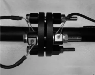
Two major approaches in this measurement method include the use of electrical impedance and electromechanical impedance. As shown in Figure 3, In this method, first piezoelectric transducers, which play the role of sensors as well as operators, are installed in specified points on the structure. In the electrical impedance measurement method, an electric pressure difference is applied on two sides of an electrode, and using an impedance analyzer, the level of electrical resistance (or imped-ance) is calculated based on the ratio of the voltage to the electric current in different frequencies. In the electromechanical impedance measurement method, the structure is stimulated with different piezoelectric elements and by analyzing the electromechanical response of the structure to the ap-plied stimulation, the amount of impedance is determined using an impedance analyzer (Liang, et al., 1994; S.Zhou, et al., 1995; Annamdas & Soh, 2007; Overly, et al., 2007).
Figure 3: A sample section of a pipeline with electromechanical impedance test devices (Rosiek, et al., 2012).
The most salient feature of these methods is their high sensitivity to flaws, especially contact-related flaws. In fact, in such cases, the looseness of the structure has an impact on the firmness and attenuation of the joints and consequently on the impedance value of the structure. Besides, not only is this method used in troubleshooting of complex structures, but also due to its special func-tion, it can be used in online monitoring of the conditions. Despite numerous advantages, this method has drawbacks, as well. The number of sensors and functions required for this method, es-pecially in structures having a great number of bolts, is an unfavorable factor. Moreover, the meth-od demonstrates unsatisfactory performance in systems with thermal fluctuations or loading (Annamdas & Soh, 2007; Huynh, et al., 2015).
empir-ically, having a wave dispersal approach; while they provided indices to quantify the amount of looseness, they examined the sensitivity of indices to firmness and attenuation of joints (Ritdumrongkul, et al., 2004). Providing an index for evaluation of the looseness of bolts, Park et al. surveyed the efficiency of the method in detecting looseness in bolted joints of pipelines (Overly, et al., 2007; Park, et al., 2001). Pavelko et al. also conducted experiments on thin plates, and by investigating the effects of structure firmness, they described the mechanism of this method (Pavelko, et al., 2011). In addition to the conducted case studies, innovations have also been pro-posed in performing the experiments. Wait et al. propro-posed merging impedance measurement meth-ods with lamb waves (Wait, et al., 2005) and An and Sohn (An & Sohn, 2012) asserted to improved efficiency of impedance measurements while using guided ultrasonic waves. Mascarenas et al. (Mascarenas, et al., 2009) suggested a new setup for impedance method which made use of wireless data-collection equipment.
3.2 Vibration Based Methods
Another indirect method for detection of looseness of bolted structures is analyzing vibration signals obtained from such joints and structures. As looseness results in reductions in firmness of joints and structures, its detection is possible if variations and fluctuations of the structure’s vibration parame-ters are monitored. In these methods, it is assumed that a structure which suffers from looseness, emits nonlinear vibration responses due to the existence of flaws and changes in vibrational and dynamic parameters. Vibration application in this group of methods is performed through several ways, the most important of which is using hammers, vibrators or piezoelectric elements; the selec-tion depends on the structure’s size, work condiselec-tions and test costs. In this method, vibraselec-tional stimulation is carried out using one of the mentioned methods and the responses are recorded using a piezoelectric accelerometer or laser vibrometer. The received signals are then analyzed considering time, frequency, time-frequency or frequency-time to allow for detection of dynamic parameter changes due to the flaws (Tanner, et al., 2003; I. Milanese, 2008; He & Zhu, 2014; Feblil, et al., 2013; Sohn, et al., 2004).
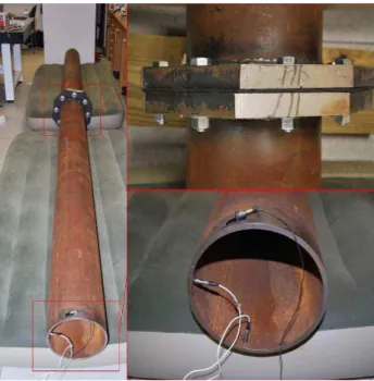
Figure 4: A steel pipeline with bolted flanges and the placement of the accelerometers (He & Zhu, 2014).
in-vestigations, proved the efficiency of the method. Guarino and Hamilton (Guarino & Hamilton, 2009) investigated the vibrational signals obtained from impacts to metal structures and Esmaeel et al. (Esmaeel, et al., 2012) and He and Zhu (He & Zhu, 2014) examined ways to diagnose and evalu-ate looseness of flange bolts in pipelines which a simple setup of their test is shown in Figure 4. Besides these studies, innovations have also been made by scholars regarding signal processing and analysis of vibrational signals. Nichols et al. (Nichols, 2007) obtained vibrational responses from a bolted structure and, using Fourier transform, extracted the linear response ratio of the vibrational signal. Subsequently, comparing the obtained response with the linear response, he estimated the amount of flaw in the structure. Milanese et al. (Milanese, et al., 2008) detected structure looseness via analyzing vibrational signals and investigating the frequency content of systems. Razi et al. (Razi, et al., 2013) used the empirical mode decomposition method to do so.
3.3 Ultrasonic Based Methods
Another set of methods used to monitor bolt conditions, which possess a high level of favorability, are ultrasonic-based methods. In this category of methods, the changes in the ultrasonic wave sent to a structure is examined as an index for the existence of flaw. The waves used in this category of methods could be longitudinal, transversal or surface and could be used either in pulse-echo or transmission methods. In the pulse-echo method, the piezoelectric sensor and actuator – which are often of PZT type – are placed at one side of the structure and they send and receive the ultrasonic waves. In the transmission method, the sensor and operator are placed at opposite poles of the structure and the wave is sent at one side and the response is received at the other side (Rose, 1999).
These methods investigate the ultrasonic signal which passes through the flawed structure by studying linear phenomena like reflection and scattering of the waves as well as nonlinear phenome-na such as modulation of sigphenome-nals, energy wastage, etc. Among the proposed methods, according to research studies, the guided waves and lamb waves methods are two of the most practical ultrasonic stimulation methods. Guided waves are named so because their scattering is reliant upon the geom-etry of the structure, and the boundaries of the parts or of the structure help guide the waves in definite directions. The advantage of these waves is their ability to travel longer distances inside the structure and cover greater depth in the sample. Lamb waves are in fact a type of guided waves and they are used in troubleshooting of bolted structures. The difference is that their frequency range is dissimilar and they are often used to troubleshoot thinner structures (Rose, 1999; Meo & Amerini, 2011; Park, et al., 2015; Wang, et al., 2013; Joshi & Pathare, 1984; Alleyne & Cawley, 1992; Cawley & Alleyne, 1996; Cho, 2000; Raghavan & Cesnik, 2007; Park, et al., 2006).
3.3.1 Piezo Active Sensing Method
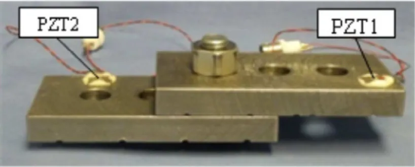
As was mentioned, the amount of energy wastage of ultrasonic waves which are spread through the structure is considered as an index. Figure 2 displays the mechanism of this method. In this meth-od, piezoelectric elements are attached to both sides of the bolted joint and the ultrasonic signals are sent via one and received through the other. As all the surfaces in structures and joins are rough, ultrasonic waves are always subject to wastage of energy. However, it should be noted that if the structure remains steady, the amount of energy wastage will be constant, too. In fact, in this method, the increase in energy wastage accounts for the change in structure conditions and there-fore represents looseness of bolts.
The advantage of this method is its ability to allow for instantaneous monitoring of conditions due to its function. In addition to this, the frequency range used for stimulation purposes in this method is relatively low and as a result there will be no need for sampling equipment with high frequency, which leads to comparatively lower costs. However, in this method, if a structure with a great number of bolts is to be investigated, the high number of sensors, operators and connectors will result in an increase in the volume of test equipment and will probably incur higher costs (Wang, et al., 2013).
Figure 5: An example of the equipment used in the piezo active sensing method (Wang, et al., 2013).
3.3.2 Acoustoelastic Effect Based Methods
Acoustoelastic effect is built upon the assumption that the velocity and frequency of scattered waves throughout the bolt is closely associated with the preload in it (Wang, et al., 2013). In this method, the ultrasonic wave is sent into the material and based on the variations made in transfer velocity or resonance frequency due to the acoustoelastic effect, the existing stress field in the struc-ture is estimated. This method has numerous application in estimating residual stress field in weld-ed steel plates (Salamanca & Bray, 1996; Tanala, et al., 1995), railways (Hirao, et al., 1994; Szela̧żek, 1992), rods (Chen, et al., 1998) and multi-wire stands (Chen & Wissawapaisal, 2002; Di-Scalea, et al., 2003; Kwun & K. A. Bartels, 1998; Rizzo, et al., 2003; Washer, et al., 2002). Another area of usage for acoustoelastic-based methods is their application in detection of the looseness de-gree of bolts and assuring the adequacy of axial force on joints (Chaki, et al., 2006; Chaki, 2007; Johnson, et al., 1996).
Three of the most important usages for this purpose include the time of flight method, velocity ratio method and mechanical resonance frequency method. These methods, as will be discussed in the following sections, measure preload of bolts using one of the following traits: (1) the transfer time of the ultrasonic wave throughout the bolt, (2) the ratio of transfer time of the longitudinal wave to ultrasonic transverse wave in the bolt, and (3) mechanical resonance frequency shift meth-od in the bolt (Wang, et al., 2013).
Time of Flight Methods (TOF)
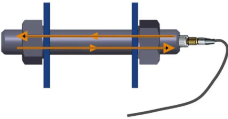
As was explained previously, according to the acoustoelastic effect, the stress field in a bolted struc-ture can affect the scattering velocity of the wave inside the material. The theoretical basis of this method, as was mentioned above, is acoustoelastic. As shown in Figure 6, in this method, the piezo-electric element is stuck to one side of the bolt and the ultrasonic wave is sent into the segment in pulse-echo forms. This should be repeated both for stress-free joints and for joints which display stress due to the application of torque, with the flight time of the wave being measured each time. By recording the two times and using the overall relations which Kelly et al. and Johnson et al. used for homogenous and isotropic material, stress field and consequently the axial force of the joint can be calculated (Johnson, et al., 1996).
Figure 6: Schematic of TOF mechanism.
Velocity Ratio Method
As was mentioned, since in most cases, it is not possible to remove bolts and test them in a stress-free state, it is not practical to use the time of flight method. Because of this, the velocity ratio method was proposed, which can estimate the axial force of the structure using the ratio of flight time of longitudinal waves to transversal waves under stress conditions. The method functions like the previous one, with the difference being that there is no need to dissemble or assemble the bolted structure and access to one side of the bolt makes the test possible. In addition to the mentioned advantages for this method, unlike the previous one, it is not necessary to have the exact length of bolts and its theoretical relationships is independent of the length of bolts and flight time in stress-free states. However, like the previous method, its main disadvantage is that flight time ratio fluc-tuations of the transversal wave to the longitudinal wave are marginal and its measurement re-quires sampling equipment with high accuracy, which will mean more costs (Chaki, 2007; Johnson, et al., 1996).
Mechanical Resonance Frequency Shift Method
In a bolted structure, acoustic resonance frequency is a function of bolt length and wave propaga-tion velocity. Furthermore, when a bolted structure is under stress due to applicapropaga-tion of torque, these two parameters are influenced because of the acoustoelastic effect. The mechanical resonance frequency shift method is built upon these two assumptions. In this method, by monitoring acoustic resonance frequency variations, it is possible to estimate the stress field and consequently the axial force of the joint. However, in this method, like the two previous ones, as the fluctuations of reso-nance frequency are slight, there is a need for sampling equipment with a measurement sensitivity in megahertz, and this implies significantly high costs (S. J. Temitop, 2015; Wang, et al., 2013; Nguyen, et al., 2011).
experimental results suggested the existence of a linear relationship between the frequency transfer and the applied stress. Based on the pseudo-continuous wave technique, Joshi and Pathare (Joshi & Pathare, 1984) recommended the phase detection method to detect the amount of resonance fre-quency shift and approved of the linear relationship between the frefre-quency transfer and the applied stress proposed by Jeyman. Later, Johnson et al. (Johnson, et al., 1996) in 1986 studied the efficien-cy of the velocity ratio method for the first time. Although at first, the accuraefficien-cy of the empirical results obtained by them did not draw attentions, Yausi and Kawashima investigated the efficiency of the time of flight method and velocity ratio and gained more acceptable results using longitudinal and transversal waves with frequencies of 5 and 10 megahertz respectively (Kawashima & Yasui, 2000).
Hamdan et al. (Liew, et al., 2006) also did experiments on bolted joints in steel structures and obtained similar results for the time of flight method. In addition to the case studies conducted on methods which are based on the acoustoelastic effect, innovations have also been achieved and pro-posed in terms of test performance and signal analysis by scholars. Hirao et al. (Hirao, et al., 1994) used non-contacting shear-wave electromagnetic acoustic transducer (EMAT) in the time of flight method and they demonstrated that there is a linear relationship between the flight time and axial force of the structure. Jhang et al. (Jhang, et al., 2006) suggested a new method named phase de-tection method for precise measurements of flight time. They showed that the measurements of velocity fluctuations of the ultrasonic wave in the time of flight method, which is sensitive to the surrounding noises, requires extremely accurate equipment and high expenses; the phase detection method could reduce the costs significantly. Besides, the results obtained by their proposed method showed that there is a linear relationship between the increase in the stress in the structure and the decrease in wave velocity.
3.3.3 Methods Based on Emergence of Harmonics
To begin with, as will be explained, it should be noticed that there is a difference between the sec-ond harmonic method and side band method. In the secsec-ond harmonic method, the stimulation sig-nal is ultrasonic, while in the side band method, the system is simultaneously stimulated with vi-brational and ultrasonic signals. Although both methods display similar results in terms of frequen-cy, there are essential differences in various aspects, as will be explained below.
Second Harmonic Method
The emergence of higher harmonics is among the phenomena that is observed in signal analysis of structures. This phenomenon generally happens for two major reasons: presence of nonlinear effects in the material and/or presence of nonlinear effects in surfaces in contact. The flaws due to the first reason can be explained by the Hook Law and by considering nonlinear terms (Rokhlin, et al., 1981; Jhang, 2000; Barbieri, et al., 2009). However, in the case of flaws in bolted structures, the second reason is bolder.
fre-quently observed empirically, but it also can be explained by contact acoustic nonlinearity (CAN) theories (Duke & Kiernan, 1988).
Figure 7: An example of experimental setup for second harmonic generation (Zhang, et al., 2016).
According to Figure 7 which show an example of experimental setup for second harmonic gen-eration method, in this method, the ultrasonic wave enters the structure via either pulse-echo or transmission methods through the piezoelectric element and, while the wave passes the structure, the structure’s response to this wave is obtained. If the axial force of the bolted structure is inade-quate and the bolts are loose, the contact surfaces are not bolted firmly or flawlessly and the acous-tic impedance is increased; hence, the second harmonic will appear in the response signal in the Fourier space. The bigger the range of the appeared harmonic, the worse the flaw in the joint (Hikata, et al., 1963; Kim, et al., 2006; Cantrell & Yost, 20001; Frouin, et al., 1999).
Side Band Methods
This group of methods is an integration of methods based on vibration and those based on ultrason-ic. In general, in these methods, the vibration and ultrasonic signal enter the structure simultane-ously and the presence of factors causing nonlinear effects like crack, delamination, looseness of bolts, etc. will cause modulation in the signals. The caused modulation in the frequency area will be represented as side bands components and an increase in the range of these components would mean an increase in the amount of flaw. Overall, these methods are divided into two groups based on the type of the vibrational stimulation: impact modulation and vibroacoustic modulation meth-od. If the vibration signal is applied using a hammer, the method is called impact modulation and if a shaker is used for the stimulation, it is named vibroacoustic modulation. It should be noted that in both methods, piezoelectric elements are used to produce ultrasonic signals. The reception of the system’s response signal can also be performed in different ways depending on the experimental conditions. The most important and practical ways include using piezoelectric, electromagnetic ac-celerometers and laser vibrometers (Polimeno, et al., 2008; Meo & Zumpano, 2005; Meo & Zumpano, 2007; Zumpano & Meo, 2008; Meo M, 2007; Polimeno & Meo, 2008; Kawashima, et al., 2006; Abeele, et al., 2000; Straka, et al., 2008; Donskoy, et al., 2001).
in Figure 8, the response signals modulate each other in case of contact flaws like looseness of bolted structures. In such a condition, there will be side bands with integral multiple intervals from the vibration frequency around the ultrasonic frequency. In theoretical terms, the components have equal ranges, but the experimental results do not approve of this. After the reception of the modu-lated signals, the signal is analyzed. Given an index defined in order to investigate the amount of modulation, the amount of the index is measured for different applied torque values and the rela-tionship between the amount of looseness of the structure and the value of the index is determined (Meo, 2011; Amerini, et al., 2010).
Figure 8: Modulation phenomenon for a loosening bolt (Meo & Amerini, 2011).
The main advantage of methods based on harmonics is their relatively high accuracy in compar-ison with other ultrasonic methods. As was mentioned above, ultrasonic methods are often based on linear phenomena like reflection, scattering, etc. which have lower accuracy compared to methods such as the side band one which are used for monitoring of nonlinear phenomena like modulation. Besides, if the performance vibration of the structure itself is used as vibration signals in the side band method, online monitoring of the structure would also be possible. The important point is that in this method, although there is a high level of accuracy and efficiency in detection of loosened structures, which is approved in detection and evaluation of other flaws in structures, no compre-hensive reason has ever been proposed for the occurrence of modulation (Meo & Zumpano, 2005; Broda, et al., 2014).
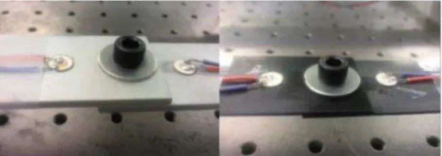
quanti-fy the amount of looseness, they utilized the hyperbolic tangent curve. Adams and Meyer (Meyer & Adams, 2015) also surveyed the efficiency of the impact modulation method theoretically and exper-imentally. They first proposed a theoretical model for looseness of two connected metal plates, then performed a troubleshooting by numerical simulations, and finally validated their model by compar-ing the results with experimental ones. An example of experimental setup for Impact Modulation method is shown in Figure 9.
Figure 9: An example of experimental setup for Impact modulation method (Jaques & Adams, 2011).
3.4 Other Indirect Methods
Apart from the proposed methods in the previous sections, there are other methods suggested by scholars which are capable of detecting and evaluating looseness in bolted structures. However, the methods have not been employed widely. These methods are described below.
Acoustic Moment Method
This method is a combination of ultrasonic and acoustic methods and its main advantage is that, like ultrasonic methods, it does not require a definite path for the movement of the wave. Besides, it has displayed acceptable efficiency in detection of looseness in heterogeneous materials. The major disadvantage of the method is that the obtained signals in this method are vague and they contain a great deal of noise. In fact, due to the presence of such noises, specific probes should be employed in this method, and this means a higher cost to perform the test (Kwon & Lee, 1999; Meo & Amerini, 2011). Alleyne and Cawley (Alleyne & Cawley, 1992) and Vary and Bowles (Vary & Bowles, 2004) were among the researchers who investigated the efficiency of this method in detect-ing flaws in bolted structures and showed that by measurdetect-ing the acoustic moment of a bolted struc-ture, a great deal of information could be obtained about the structure.
Image Processing Based Methods
purposes is methods based on image analysis. Image analysis is the process of using the computer to digitalize the image and detect the changes in the section or structure by comparing the images. This process includes five main steps: (1) taking photos of the structure using a digital camera, (2) preparing the images before the main analysis, (3) selecting the part of the picture to be analyzed, (4) extracting differences by comparing the images, and (5) interpreting the results from the previ-ous step and detecting the flaws (Park, et al., 2015; Huang, et al., 2009). The efficiency of the method in detection of different flaws like cracks (Abdel-Qader & Kelly, 2003; Hutchinson & Chen, 2006; Yamaguchi & Hashimoto, 2010; Subirats, et al., 2006; Zou, et al., 2012), corrosions (Choi & Kim, 2005; Lee, et al., 2006) or even online monitoring of cable bridges (Ho, et al., 2013; Fukuda, et al., 2013) has been proven by various studies.
The positive point about this method is that it yields a quantitative and tangible analysis of the investigation which is minimally affected by environmental noises. Also, the test costs are low and the main cost is allocated to purchasing the camera. Moreover, it is possible to investigate larger structures with a camera and this removes the problems related to the size of the sample under investigation. However, the problem with the method is that due to slight differences in the length of the bolts in a structure, the detection of changes is difficult (Park, et al., 2015).
Radio Waves Processing Based Methods
These methods are based upon the fact that looseness of bolts usually involves some sort of rotating of bolts or nuts and monitoring this rotation can be used in detection of looseness. To this end, an RFID tag is placed on bolts and their placement is adjusted to zero degree of rotation. If the loose-ness process and consequently any spinning happens, the change is detected by a reader and dis-played in interface software. Experiments have shown that the relationship between the reader and the tag for angles lower than 20 degrees yields best efficiency (Wu, et al., 2016).
Methods Based on Electromagnetic Fields
These methods are based on bolt rotation in the process of looseness. In this method, a cover con-taining a coil is placed on nuts or bolt heads. When the bolt starts to spin due to looseness, the magnetic field is changed and the looseness is detected. The theoretical basis for this method is simple, but the problem is that it can be used for one bolt only and this could cause problems for structures with a high number of bolts. Moreover, the looseness usually involves slight spinning and with such slight rotations, the changes in the magnetic field would be small, too, which results in a reduction in accuracy of the method (Park, et al., 2015; You, et al., 2010).
Methods Based on Electric Potential
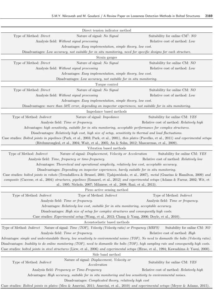
Direct tension indicator method
Type of Method: Direct Nature of signal: No Signal Suitability for online CM1: NO
Analysis field: Without signal processing Relative cost of method: Low
Advantages: Easy implementation, simple theory, low cost.
Disadvantages: Low accuracy, not suitable for in situ monitoring, need for specific designs for each structure.
Strain gauges
Type of Method: Direct Nature of signal: No Signal Suitability for online CM: NO
Analysis field: Without signal processing Relative cost of method: Low
Advantages: Easy implementation, simple theory, low cost.
Disadvantages: Low accuracy, not suitable for in situ monitoring.
Torque control
Type of Method: Direct Nature of signal: No Signal Suitability for online CM: NO
Analysis field: Without signal processing Relative cost of method: Low
Advantages: Easy implementation, simple theory, low cost.
Disadvantages: more than 50% error, depending on inspector experiences, not suitable for in situ monitoring.
Impedance based methods
Type of Method: Indirect Nature of signal: Impedance Suitability for online CM: YES
Analysis field: Time or frequency. Relative cost of method: Relatively high
Advantages: high sensitivity, suitable for in situ monitoring, acceptable performance for complex structures.
Disadvantages: Relatively high cost, high size of setup, sensitivity to thermal and load fluctuations.
Case studies: Bolted joints in pipelines (Park, et al., 2003; Park, et al., 2001), thin plates (Pavelko, et al., 2011) and experimental setups
(Ritdumrongkul, et al., 2004; Wait, et al., 2005; An & Sohn, 2012; Mascarenas, et al., 2009).
Vibration based methods
Type of Method: Indirect Nature of signal: Displacement, Velocity or Acceleration Suitability for online CM: YES
Analysis field: Time, frequency or time-frequency. Relative cost of method: Relatively low
Advantages: Theoretical and operational simplicity, relatively low cost, acceptable accuracy.
Disadvantages: Depending on inspector experiences, barely suitable for in situ monitoring.
Case studies: bolted joints in robots (Trendafilova & Brussel, 2001; Tjahjowidodo, et al., 2007), metal (Guarino & Hamilton, 2009) and composite (Caccese, et al., 2004) structures, pipelines (Esmaeel, et al., 2012) and experimental setups (Adams & Farrar, 2002; Wit, et
al., 1995; Nichols, 2007; Milanese, et al., 2008; Razi, et al., 2013).
Piezo active sensing method
Type of Method: Indirect Type of Method: Indirect Type of Method: Indirect
Analysis field: Time or frequency. Analysis field: Time or frequency.
Advantages: Relatively low cost, suitable for in situ monitoring, acceptable accuracy.
Disadvantages: High size of setup for complex structures and consequently high costs.
Case studies: Experimental setup (Wang, et al., 2013; Chang & Yang, 2006; Doyle, et al., 2010).
Acoustoelastic based methods
Type of Method: Indirect Nature of signal: Time (TOF), Velocity (Velocity ratio) or Frequency (MRFS) Suitability for online CM: NO
Analysis field: Time or frequency. Relative cost of method: High
Advantages: simple and understandable theory, low sensitivity to environmental noises (TOF), No need to dismantle the bolts (Velocity ratio).
Disadvantages: Inability to do online monitoring (TOF), need to dismantle the bolts (TOF), high sampling rate and consequently high costs.
Case studies: bolted joints in steel structures (Liew, et al., 2006) and experimental setups (Hirao, et al., 1994; Kawashima & Yasui, 2000).
Side band method
Type of Method: Indirect Nature of signal: Displacement, Velocity or
Acceleration Suitability for online CM: YES
Analysis field: Frequency or Time-Frequency Relative cost of method: Relatively high
Advantages: High accuracy, suitable for in situ monitoring and low sensitivity to environmental noises.
Disadvantages: Complicated theory, relatively high cost
Case studies: Bolted joints in plates (Meo & Amerini, 2011; Amerini, et al., 2010) and experimental setups (Meyer & Adams, 2015).
Table 1: Summary of direct and indirect methods used in evaluation of bolted structures.
4 CONCLUSION
As was mentioned above, due to the fact that looseness begins with a decrease in the amount of axial force, the measurement and estimation of this force is among the most important strategies in monitoring bolted structures. To do this, there are various methods, the most useful of which are presented in Table 1. As was shown, direct measurement methods, while possessing simple theoreti-cal basis and being easier to use, are employed less due to their low accuracy and significant error. In fact, because of this, the methods are less discussed in academic papers or for the investigation of important structures, though they are stated in standards. Among the methods presented in Table 1, those based on the acoustoelastic effect are hardly used for online monitoring of conditions. This is not the only problem of this group of methods, though, and the cost of the test is also significant-ly high, due to the high frequency sampling equipment. Even though the rest of the methods have the capacity to be used for online condition monitoring, the test expense is a noteworthy factor to be considered by the inspector. Lower costs would be incurred by the methods which are based on vibration and the piezo active sensing method. While both of these methods are based on monitor-ing variations of linear parameters, they have less accuracy, compared to non-linear methods. Due to this very reason, side bands methods which include the impact modulation and vibroacoustic modulation methods are regarded as the methods with the highest amount of sensitivity in detect-ing looseness in bolted structures, though the methods have theoretically complicated basis and would include relatively high expenses.
Thus, a number of different parameters should be taken into account when choosing the best method for detection and evaluation of looseness of bolted structures and consequently of axial force, the most salient of which are test accuracy, test cost and the feasibility of online monitoring. In fact, it is the circumstances under which the test must be performed and the required amount of accuracy that determine the importance of key parameters in choosing the most suitable method.
References
Abdel-Qader, I. Abudayyeh, O., & Kelly, M.E., 2003. Analysis of edge-detection techniques for crack identification in bridges. J. Computing in Civil Engineering ASCE, 17(4), pp. 255-263.
Abeele, K. E. V. D., Carmeliet, J., Cate, J. A. T. & Johnson, P. A., 2000. Nonlinear elastic wave spectroscopy (NEWS) techniques to discern material damage, Part II: Single-mode nonlinear resonance acoustic spectroscopy. Res Nondestruct Eval, 12(1), pp. 31-42.
Adams, D. & Farrar, C., 2002. Classifying linear and nonlinear structural damage using frequency domain arx mod-els. Structural Health Moniting, 1(2), pp. 185-201.
Alleyne, D. & Cawley, P., 1992. The interaction of Lamb waves with defects. IEEE Trans. Ultrason. Ferroelectr. Freq. Control, Volume 39, pp. 381-397.
Amerini, F., Barbieri, E., Meo, M. & Polimeno, U., 2010. Detection loosening/tightening of clamped structures using nonlinear vibration techniques. Smart materials and structures, Volume 19.
An, Y. K. & Sohn, H., 2012. Integrated impedance and guided wave based damage detection. Mechanical Systems and signal processing, Volume 28, pp. 50-62.
Annamdas, V. G. M. & Soh, C. K., 2007. Three Dimensional Electromechanical Impedance Model.I: Formulation of Directional Sum Impedance. Journal of Aerospace Engineering, Volume 20153-62.
Barbieri, E., Meo, M. & Polimeno, 2009. Nonlinear wave propagation in damaged hysteretic materials using a fre- quency domain-based PM space formulation. Int J Solids Struct, 46(1), p. 165–180.
Bhalla, C. S. S., 2004. Structural Health Monitoring by Piezoimpedance Transducers. I: Modelling. Journal of Aero-space Engineering, 14(4), pp. 154-165.
Bickford, J. H., 2007. Introduction to the Design and Behavior of Bolted Joints. Fourth Edition ed. s.l.:s.n.
Bickford, J., 2008. Other ways to control Preload. In: Introduction to the design and behavior of bolted joints: non-gasketed joints. s.l.: CRC Press, pp. 197-216.
Broda, D. et al., 2014. Modelling of nonlinear crack–wave interactions for damage detection based on ultrasound—A review. Journal of Sound and Vibration, Volume 333, pp. 1097-1118.
Caccese, V., Mewer, R. & Vel, S. S., 2004. Detection of bolt load loss in hybrid composite/metal bolted connections. Engineering Structures, 26(7), pp. 895-906.
Cantrell, J. H. & Yost, W. T., 2001. Nonlinear ultrasonic characterization of fatigue microstructures. Int J Fatigue, 23(1), pp. 487-490.
Cawley, P. & Alleyne, D., 1996. The use of Lamb wave for the long range inspection of large structures. Ultrasonics, Volume 34, pp. 287-290.
Chaki, S., Corneloup, G., Lillamand, I., & Walaszek, H., 2006. Nondestructive control of bolt tightening: absolute and differential evaluation. Materials Evaluation, 64(6), pp. 629-633.
Chaki, S., Corneloup, G., Lillamand, I., & Walaszek, H., 2007. Combination of Longitudinal and Transverse Ultra-sonic Waves for In Situ Control of the Tightening of Bolts. Journal of Pressure Vessel Technology, 129(3).
Chang, J. & Yang, F. K., 2006. Detection of bolt loosening in C—C composite thermal protection panels: II. Exper-imental verification. Smart Materials and Structures, 15(2), pp. 591-599.
Chen, H. L. R., He, Y. & GangaRao, H. V., 1998. Measurement of prestress force in the rods of stressed timber bridges using stress waves. Materials evaluation, 56(8), pp. 977-981.
Chen, H.-L.(R.), & Wissawapaisal, K., 2002. Application of Wigner-Ville Transform to Evaluate Tensile Forces in Seven-Wire Prestressing Strands. Journal of Engineering Mechanics, 128(11), pp. 1206-1214.
Cho, Y., 2000. Estimation of ultrasonic guided wave mode conversion in a plate with thickness variation. IEEE Trans.Ultrason. Ferroelectr. Freq. Control, Volume 47, pp. 591-603.
Choi, K. Y. & Kim, S. S., 2005. Morphological analysis and classification of types of surface corrosion damage by digital image processing. Corrosion Science, Volume 47, pp. 1-15.
Conradi, M. S., Miller, J. G. & Heyman, J. S., 1974. A transmission oscillator ultrasonic spectrometer. Review of Scientific Instruments, 45(3), pp. 358-360.
Crecraft, D., 1967. The measurement of applied and residual stresses in metals using ultrasonic waves. Journal of Sound and Vibration, 5(1), pp. 173-192.
Di-Scalea, F., Rizzo, P., Seible, F. & Asce, M., 2003. Stress measurement and defect detection in steel strands by guided stress waves. J Mater Civil Eng, 15(3), pp. 219-227.
Donskoy, D., Sutin, A. & Ekimov, A., 2001. Nonlinear acoustic interaction on contact interfaces and its use for nonde- structive testing. NDT&E International, Volume 34, pp. 231-238.
Doyle, D., Zagrai, A., Arritt, B. & Akan, H. C., 2010. Damage detection in bolted space structures. Journal of Intel-ligent Material Systems and Structures, 21(3), pp. 251-264.
Esmaeel, R. A., Briand, J. & Taheri, F., 2012. Computational simulation and experimental verification of a new vibration-based structural health monitoring approach using piezoelectric sensors. Structural Health Monitoring, 11(2).
Feblil, H., Itsuro, K., Hosoya, N. & Kawamura, S., 2013. Bolt loosening analysis and diagnosis by non-contact laser excitation vibration tests. Mechanical Systems and Signal Processing, Volume 40, pp. 589-604.
Feenstra, et al., 2005. Model Validation of Loose Bolted Joints in Damaged Structural Systems. Orlando, FL, s.n. Frouin, J., Matikas, T. E., Na, J. K. & Sathish, S., 1999. Insitu monitoring of acoustic linear and nonlinear behavior of titanium alloys during cyclic loading. s.l., s.n., pp. 107-116.
Fukuda, Y. et al., 2013. Vision-based displacement sensor for monitoring dynamic response using robust object search algorithm. IEEE Sensor Journal, 13(12), pp. 4725-4732.
Goodier, J. N., 1945. Loosening by vibration of threaded fastenings. Mechanical Engineering, Volume 67, pp. 798-802.
Groper, M., 2009. Microslip and macroslip in bolted joints. Experimental mechanic, Volume 25.
Guarino, J. & Hamilton, R., 2009. Acoustic detection of bolt detorquing in structures. s.l., Acoustical Society of America.
He, K. & Zhu, W. D., 2014. Detecting Loosening of Bolted Connections in a Pipeline Using Changes in Natural Frequencies. Journal of Vibration and Acoustic, 136(3).
Hess, D. P., 1988. Vibration and shock-induced loosening. In: Handbook of bolts and bolted joints. New York: Mar-cel Dekker, pp. 757-824.
Hess, D. P. & Basava, S., 1998. Bolted joint clamping force variation due to axial vibration. Journal of Sound and Vibration, Volume 210, pp. 255-265.
Heyman, J. S., 1977. A CW ultrasonic bolt-strain monitor. xperimental Mechanics, 17(5), pp. 183-187.
Heyman, J. S. & Churn, E., 1992. Ultrasonic measurement of axial stress. Journal of Test Evaluation, 10(5), pp. 202-211.
Hikata, A., Chick, B. B. & Elbaum, C., 1963. Effect of dislocations on finite amplitude ultrasonic waves in alumi-num. Appl Phys Lett, 3(11), pp. 195-197.
Hirao, M., Ogi, H. & Fukuoka, H., 1994. Advanced ultrasonic method for measuring rail axial stresses with electro-magnetic acoustic transducer. Research in Nondestructive Evaluation, 5(3), pp. 211-223.
Ho, H. N., Kim, K. D., Park, Y. S. & Lee, J. J., 2013. An efficient image-based damage detection for cable surface in cable-stayed bridges. NDT&E International, Volume 58, pp. 18-23.
Hong, M. & Kim, N., 2009. Measurement of axial stress using mode-converted ultrasound. NDT & E International, 42(3), pp. 164-169.
Huang, Y. H., Liu, L. & Hung, Y. Y., 2009. Real-time monitoring of clamping force of a bolted joint by use of automatic digital image correlation. Optics & Laser Techonology, Volume 41, pp. 408-414.
Hutchinson, T. C. & Chen, Z., 2006. Improved image analysis for evaluating concrete damage. J. Computing in Civil Engineering ASCE, 20(3), pp. 200-216.
Huynh, T. C., Lee, K. S. & Kim, J. T., 2015. Local dynamic characteristics of PZT impedance interface on tendon anchorage under prestress force vibration. Smart structures and systems, 15(2), pp. 375-393.
Milanese, A., Marzocca, P., Nichols, J.M., Seaver, M., Trickey, S.T., 2008. Modeling and detection of joint loosening using output-only broad-band vibration data. Structural Health Monitoring, 7(4), pp. 309-328.
Bickford, J.H., 2008. Introduction to design and behavior of bolted joints: non-gasketed joints. Boca Raton: CRC Press.
Jaques, J. & Adams, D., 2011. Using Impact Modulation to Identify Loose Bolts on a Satellite, Purdue: Air force research laboratory space vehicles directorate.
Jhang, K. Y., 2000. Applications of nonlinear ultrasonics to the NDE of material degradation. IEEE Trans Ultrason Ferroelectr Freq Control, 47(3), pp. 540-548.
Jhang, K. Y., Quan, H. H., Ha, J. & Kim, N. Y., 2006. Estimation of clamping force in high-tension bolts through ultrasonic velocity measurement. Ultrasonics, Volume 44, pp. 1339-1342.
Johnson, G. C., Holt, A. C. & Cunningham, B., 1996. An ultrasonic method for determining axial stress in bolts. Journal of test and evaluation, 14(5), pp. 253-259.
Joshi, S. G. & Pathare, R. G., 1984. Ultrasonic instrument for measuring bolt stress. Ultrasonics, 22(6), pp. 270-274. Junker, G., 1969. New criteria for self-loosening of fasteners under vibration. SAE Transaction, Volume 78, pp. 314-335.
Kawashima, H. & Yasui, K., 2000. Acoustoelastic measurement of bolt axial load with velocity ratio method. Italy, Rome, s.n., pp. 750-756.
Kawashima, K. et al., 2006. Nonlinear ultrasonic imaging of imperfectly bonded interfaces. Ultrasonics, 44(1), pp. 1329-1333.
Kim, J. Y., Jacobs, L. J., Qu, J. & Littles, J. W., 2006. Experimental characterization of fatigue damage in a nickel-base super- alloy using nonlinear ultrasonic waves. J Acoust Soc Am, 120(3), pp. 1266-1273.
Krishnamurthy, K., Lalande, F. & Rogers, C. A., 1996. Effects of temperature on the electrical impedance of piezoelectric sensors. Proc. SPIE 2717.
Kwon, O. Y. & Lee, S. H., 1999. Acousto-ultrasonic evaluation of adhesively bonded CFRP-aluminum joints. NDT&E Int, 32(3), pp. 153-160.
Kwun, H. & K. A. Bartels, J. J. H., 1998. Effects of tensile loading on the properties of elastic-wave propagation in a strand. The Journal of the Acoustical Society of America, 103(6), pp. 3370-3375.
Lee, S., Chang, L. M. & Skibniewski, M., 2006. Automated recognition of surface defects using digital color image processing. Automation in Construction, Volume 15, pp. 540-549.
Liang, C., Sun, F. P. & Rogers, C. A., 1994. Coupled electro-mechanical analysis of adaptive material systems-determination of the actuator power consumption and system energy transfer. Journal of Intelligent Material Systems and Structures, 5(1), pp. 12-20.
Liew, F. K., Hamdan, S. & Osman, M. S., 2006. The Relationship between the Applied Torque and Stresses in Post-Tension Structures. ECNDT.
Mascarenas, D. L. et al., 2009. A low-power wireless sensing device for remote inspection of bolted joints. s.l., s.n., pp. 565-575.
Meo, M. & Zumpano, G., 2005. Nonlinear elastic wave spectroscopy identification of impact damage on a sandwich plate. Composite Structures, Volume 71, pp. 469-474.
Meo, M. & Zumpano, G., 2007. A new nonlinear elastic time reversal acoustic method for the identification and locaisation of stress corrosion cracking in welded plate-like structures-A simulation study. International Journal of Solids Structures, Volume 44.
Meo, M., Zumpano, G., Polimeno, U., 2007. Corrosion iden- tification on an aluminium plate-like structure by moni- toring the wave propagation phenomena. Corros Rev, Volume 25, pp. 213-232.
Meo, M. & Amerini, F., 2011. Structural health monitoring of bolted joints using linear and nonlinear acoustic/ultrasound methods. Structural health monitoring, Volume 10, pp. 659-672.
Milanese, A. et al., 2008. Modeling and Detection of Joint Loosening using Output-Only Broad-Band Vibration Data. 7(4), pp. 309-328.
Nguyen, K. D., Lee, S. Y. & Lee, P. Y., 2011. Wireless SHM for bolted connections via multiple PZT-interfaces and Imote2- platformed impedance sensor node. s.l., s.n.
Nichols, J. M., Trickey, S. T., Seaver, M., Motley, S. R., & Eisner, E. D., 2007. Using ambient vibrations to detect loosening of a compositeto- metal bolted joint in the presence of strong temperature fluctuations. Journal of Vibration and Acoustic, 129(6), pp. 710-717.
Nikitina, N. Y. & Ostrovsky, L. A., 1998. An ultrasonic method for measuring stresses in engineering materials. Ultrasonic, 35(8), pp. 606-610.
Overly, T. G., Park, G. & Farrar, C. R., 2007. Compact hardware development for SHM and sensor diagnostics using admittance measurements. s.l., s.n.
Pai, N. G. & Hess, D. P., 2001. Exprimental study of loosening of threaded fasteners due to dynamic shear loads. Journal of sound and vibration, 253(3), pp. 585-602.
Park, G., Cudney, H. H. & Inman, D. J., 2001. Condition monitoring using image processing for bolt joints in steel bridges. Engineering and structural dynamics, 30(10).
Park, G., Sohn, H., Farrar, C. R. & Inman, D. J., 2003. Overview of piezoelectric impedance-based health monitoring and path forward. Shock and Vibration Digest, 35(6), pp. 451-463.
Park, S., Yun, C. B. & Roh, Y., 2006. Active sensing-based real-time nondestructive evaluations for steel bridge members. KSCE J. Civil Engineering, Volume 10, pp. 33-39.
Park, J. H. et al., 2015. Novel bolt-loosening detection technique using image processing for bolt joints in steel bridges. Incheon, Korea, s.n.
Pavelko, V., Ozolinsh, I., Kuznetsov, S. & Pavelko, I., 2011. Structural health monitoring of aircraft structure by method of electromechanical impedance. s.l., s.n., pp. 207-223.
Pavelko, I., Pavelko, V., Kuznetsov, S. & Ozolinsh, I., 2014. Bolt-joint structural health monitoring by the method of electromechanical impedance. Aircraft Engineering and Aerospace Technology, 86(3), pp. 207-214.
Polimeno, U. & Meo, M., 2008. Understanding the effect of boundary conditions on damage identification process when using nonlinear elastic wave spectroscopy methods. Int J Non Linear Mech, 43(3), pp. 187-193.
Polimeno, U., Meo, M. & Almond, D., 2008. Smart nonlinear acoustic based structural health monitoring system. Adv Sci Technol, Volume 56, pp. 426-434.
Raghavan, A. & Cesnik, C., 2007. Review of guided-wave structural health monitoring. Shock Vib. Dig, Volume 39, pp. 91-114.
Razi, P., Esmaeel, R. A. & Taheri, F., 2013. Improvement of a vibration-based damage detection approach for health monitoring of bolted flange joints in pipelines. Structural health monitoring, 12(3), pp. 207-224.
Ritdumrongkul, C., Abe, M., Fujino, Y. & Miyashita, T., 2004. Quantitative health monitoring of bolted joints using a piezoceramic actuator-sensor. Smart materials and structures, 13(1), pp. 120-29.
Rizzo, P., Palmer, M. D. & Scalea, F. L. D., 2003. Ultrasonic characterization of steel rods for health monitoring of civil structures.. San Diego, s.n., pp. 75-84.
Rokhlin, S. I., Hefets, M. & Rosen, M., 1981. An ultrasonic inter- face-wave method for predicting the strength of adhesive bonds. J Appl Phys, Volume 52, pp. 2847-2851.
Rose, J. L., 1999. Ultrasonic Waves in Solid Media. s.l.:Cambridge University Press.
Rosiek, M., Martowicz, A. & Uhl, T., 2012. An Overview of Electromechanical Impedance Method for Damage Detection in Mechanical Structures. Germany, s.n.
Zhou, S., Liang, C. & Rogers, C. A., 1995. Integration and Design of Piezoceramics Elements in Intelligent Structures. Journal of Intelligent Material Systems and Structures, Volume 6, pp. 733-746.
Salamanca, T. L. & Bray, D. F., 1996. Residual stress measurement in steel plates and welds using critically refracted longitudinal (LCR) waves. Research in Nondestructive Evaluation, 7(4), pp. 169-184.
Sauer, J.A., Lemmon, D.C., and Lynn, E.K., 1950. Bolts: how to prevent their loosenings. Machine design, Volume 22, pp. 133-139.
Sohn, H., Farrar, C., Hemez, F. M. & Czarnecki, J. J., 2004. A Review of Structural Health Monitoring Literature 1996 – 2001. s.l.:Los Alamos National Laboratory.
Straka, L., Yogodzinskyy, Y., Landa, M. & Hänninen, H., 2008. Detection of structural damage of aluminum alloy 6082 using elastic wave modulation spectroscopy. NDT & E International, 41(7), pp. 554-563.
Struik, J. H. A., Fisher, J. W. & Oyeledun, A., 1973. Bolt tension control with a direct tension indicator. AISC Engineering Journal, 10(1), pp. 1-5.
Subirats, P., Dumoulin, J., Legeay, V. & Barba, D., 2006. Automation of pavement surface crack detection using the continuous wavelet transform. s.l., s.n., pp. 3037-3040.
Szela̧żek, J., 1992. Ultrasonic measurement of thermal stresses in continuously welded rails. NDT & E International, 25(2), pp. 77-85.
Tanala, E., Bourse, G., Fremiot, M. & Belleval, J. F. D., 1995. Determination of near surface residual stresses on welded joints using ultrasonic methods. NDT & E International, 28(2), pp. 83-88.
Tanner, N., Wait, J., Farrar, C. & Sohn, H., 2003. Structural health monitoring using modular wireless sensors. Journal of Intelligent materials systems and structures, 14(4), pp. 43-56.
Tjahjowidodo, T., Al-Bender, F. & Brussel, H. V., 2007. Experimental dynamic identification of backlash using skeleton methods. Mechanical Systems and Signal Processing, 21(2), pp. 959-972.
Trendafilova, I. & Brussel, H. V., 2001. Non-linear dynamics tools for the motion analysis and condition monitoring of robot joints. Mechanical Systems and Signal Processing, 15(6), pp. 1141-1164.
Ungar, E., 1973. The status of engineering knowledge concerning the damping of biult-up structures. Journal of sound and vibration, 26(1), pp. 141-154.
Vary, A. & Bowles, K., 2004. An ultrasonic-acoustic techniques for nondestructive evaluation of fiber composite quality. Polym Eng Sci, 19(5), pp. 373-376.
Wait, J. R., Park, G. & Farrar, C. R., 2005. Integrated structural health assesment using piezoelectric active sensors. Shock and Vibration, Volume 12, pp. 389-405.
Wang, T. et al., 2013. Review of bolted connection monitoring. International Journal of Distributed Sensor Network. Wang, T., Song, G., Wang, Z. G. & Li., Y. R., 2013. Proof-of-concept study of monitoring bolt connection status using a piezoelectric based active sensing method. Smart Materials and Structures, 22(8).
Washer, G. A., Green, R. E. & Pond, R. B., 2002. Velocity Constants for Ultrasonic Stress Measurement in Prestressing Tendons. Research in Nondestructive Evaluation, 14(2), pp. 81-94.
Wit, C. D., Olsson, H., Astrom, K. & Lischinsky, P., 1995. A new model for control of systems with friction. Autom. Control IEEE Trans, 40(3), pp. 419-425.
Wu, J., Cui, X. & Xu, Y., 2016. A Novel RFID-Based Sensing Method for Low-Cost Bolt Loosening Monitoring. Sensors, Volume 16.
Yamaguchi, T. & Hashimoto, S., 2010. Fast crack detection method for large-size concrete surface images using percolation-based image processing. Machine Vision and Application, Volume 21, pp. 797-809.
Zhang, Z., Liu, M., Su, Z. & Xiao, Y., 2016. Evaluation of Bolt Loosening Using A Hybrid Approach Based on Contact Acoustic Nonlinearity. s.l., s.n.
Zou, Q. et al., 2012. CrackTree: automatic crack detection from pavement images. Pattern Recognition Letters, Volume 33, pp. 227-238.