Abstract
The automotive industry is increasingly using adhesive joints bonding advanced lightweight materials to reduce vehicle weight. Strength under impact loadings is a major concern for this appli-cation and mixed adhesive joints can effectively improve the joints by combining stiffness and flexibility on the same overlap. This work introduces and studies several configurations for static and impact tests of mixed adhesive joints with four adhesives in differ-ent combinations. The main purpose of this work is the develop-ment of a strong adhesive joint using a mixed adhesive layer and perform a series of mechanical to study its mechanical behaviour. It is concluded that the use of the mixed adhesive technique im-proves both static and impact strength by introducing flexibility to the joint which subsequently allows more energy absorption when introduced in crash resistant structures.
Keywords
Dual adhesive joints; impact, mixed adhesive joints
Behaviour under Impact of Mixed Adhesive
Joints for the Automotive Industry
1 INTRODUCTION
The lightweight and complex structures used in aeronautical, automotive and aerospace industries commonly employ adhesive bonding in their manufacture (da Silva, 2011a). One of the main appli-cations of adhesive bonding in the automotive industry is the joining of complex composite and lightweight structures such as carbon fibre panels, to produce lighter, safer and more efficient vehi-cles. However, due to stringent safety standards, these bonded structures should not only be light-weight but must also be able to resist strong dynamic loadings, such as the impacts encountered in a collision.
In many adhesive joints, the need for a very strong adhesive can be unimportant, as this does not necessarily translate into a stronger joint. An adhesive must not be chosen only according to its strength but also with regards to its suitability for the environmental conditions and the loading
M. R. G. Silva a E. A. S. Marques a Lucas. F. M. da Silva b
aDepartamento de Engenharia Mecânica,
Faculdade de Engenharia, Universidade do Porto, Rua Dr. Roberto Frias, 4200-465 Porto, Portugal. [email protected]
bInstituto de Ciência e Inovação em
Engenharia Mecânica e Engenharia Industrial (INEGI), Rua Dr. Roberto Frias, 4200-465 Porto, Portugal. [email protected]
http://dx.doi.org/10.1590/1679-78252762
type (Pethrick, 2005). For high strain rate applications, the use of a stiff adhesive is not ideal. It can provide high static strength but the joint may be brittle and perform badly under impact. When selecting the adhesives for impact conditions it is then important to select one with large values of strain to failure, so that the energy absorption capacity is enhanced and the damage toler-ance increased. Standard epoxy adhesives used to increase stiffness have insufficient energy-absorption properties, which also means reduced shear strength and peel resistance under impact. Adhesive manufacturers improved on these materials by introducing rubber particles that were ly dispensed in an epoxy matrix. In the 1990s a new generation of toughened epoxy adhesives called crash-resistant adhesives, arrived on the market with good strength at high strain rates and large energy absorption capabilities (Adams, 2005).
Adams and Harris (1985) have investigated the impact behaviour of single lap joints (SLJ) with aluminium alloy specimens and concluded that, for a wide range of adhesives, the joint strength is not significantly affected by high loading rates. They found that the relationship between the joint strength and energy absorption followed an inverse proportionality, concluding that the energy ab-sorption came mainly from the deformation of the adherends. The highest energy abab-sorption was found with the use of ductile aluminium alloys adherends due to the low yield strength, while the use of high yield strength aluminium alloys resulted in low energy absorption. Goglio and Rossetto (2008), investigated the mechanical behaviour of lap joints under impact loading, focusing in the thickness of the adhesive layer. They concluded that higher joint strength could be achieved under impact loading compared to static conditions and that relatively thin adhesive layers were advanta-geous compared to thick layers, also exhibiting higher failure loads. The research of Goda and Sawa (2011) corroborates these results. In their tests, using a split Hopkinson bar apparatus, adhesive layers with a thickness of 0.2 mm provided the best results under impact.
Kadioglu and Adams (2015) investigated the behaviour of a flexible adhesive under impact loading using the SLJ configuration with high strength steel adherends, tested with a pendulum impact machine. Their results show that the lap joint strength increases considerably under impact loading compared with those under quasi-static loading and that there is a relationship between the joint performance and the loading speeds. The adhesive exhibited high strain to failure with good strength, which improves structural crashworthiness. Joint geometry can also be used to achieve similar results with a stiffer adhesive. Sato and Ikegami (2000) studied the influence of the joint geometry on the strength under impact loadings. They found that the use of tapered joints or scarfed joints instead of a SLJ provided improvements in joint strength and lowers the stress con-centration under impact loadings. According to their study, the scarf joint was identified as an op-timal configuration to maximize joint strength under impact and static loadings. Loureiro et al (2010) performed a comparison of the static and impact behaviour of stiff and flexible adhesive joints for the automotive industry. This study found that while the stiffness of the polyurethane joints is much lower than that of joints with epoxy, when the joint is subjected to high defor-mations or high strain energy, the joint with the polyurethane adhesive is stronger.
this incompatibility is the mixed adhesive joint, combining materials with vastly different properties to increase the joint strength. The main objective of the mixed adhesive joint concept is to provide stiffness and strength with one component and flexibility and impact strength with the other.
Mixed modulus joints have been proposed in the past by many researchers with the objective of improving the distribution of stresses and increasing the strength of the joints with high-modulus adhesives. The use of dual adhesive joints was first proposed by Raphael (1966), enabling the reduc-tion of stress concentrareduc-tions at the ends of the overlap, typical for SLJ. Applying a ductile adhesive in the overlap ends avoids premature joint failure. The concept entails the introduction of a more flexible adhesive at the ends of the overlap, while a stiff adhesive is employed in the central section of the joint, less subjected to deformation during loading. Hart-Smith (1973) first recognized that the use of mixed adhesive joints could yield improvements in mechanical strength for joints subject-ed to large temperature gradients. Later, Fitton and Broughton (2005) and da Silva and Adams (2007) achieved strength improvements with the use of composite adherends and an epoxy mixed adhesive on a SLJ. In the case of a single adhesive application with high stiffness, the strength of the composite joints was limited by the low through-thickness strength of the adherends, resulting in delamination of the composites, normally at the ends of the overlap where the stress concentra-tions are higher. Conversely, when a mixed adhesive joint used the same adherends, this resulted in the same strength capacity but with a cohesive failure within the bondline, which is still a more desirable result according to da Silva et. al (2011b). Breto et al (2015) performed a numerical anal-ysis of graded and mixed adhesive joints. Their preliminary work demonstrated that varying the adhesive properties along the bond-line has a significant potential to improve joint performance, even for discrete solutions such as the mixed adhesive joint. Finite elements and computation mod-els have increasingly been used to aid the selection of adhesive ratios and the mixed joint geometry. Various modern modelling techniques, such as the use of cohesive elements (de Barros 2012), can be a very powerful tool to model this type of joints and improving their strength (Sauer, 2015).
Compared to a single adhesive application on a SLJ, it is possible to improve joint strength by transferring the load uniformly along the overlap and reducing the load concentrations on the edges of the joint where the forces are normally higher and tend to create peeling effects, which are the main cause of failure in structural bonded joints. Mixed adhesive joints can have a better combina-tion of ductility and strength by using low and high modulus adhesive in the same joint, providing better results than when the same stiff adhesive is used in a standalone application. Similarly, grad-ed materials can also be usgrad-ed to improve impact behaviour (Dey et al., 2015)
According to previous research, the mixed adhesive joint can therefore be a very powerful tech-nique to improve joint performance. However, its behaviour under impact loading has not yet been evaluated. This work therefore studied the strength provided by mixed joints under impact. A com-prehensive testing procedure was undertaken, using different adhesive types and compared static and impact tests results.
2 EXPERIMENTAL PROCEDURE
2.1 Materials and Properties
For the experimental component, four adhesives were selected: two very ductile and flexible adhe-sives and two stiffer and more brittle. The ductile adheadhe-sives consist of a silicone rubber acetoxy type adhesive, Momentive (Albany, NY) RTV106 used in high temperature applications and a two-component structural acrylic adhesive type DP-8005 from 3M Scotch-weld (St. Paul, MN, USA). The stiffer adhesives consist of a very stiff and brittle epoxy adhesive, Araldite AV138/HV998 from Huntsman (Salt Lake City, UT) and a hybrid epoxy one-part system crash resistant adhesive of the XNR6852 type, the third formulation of a prototype supplied by Nagase Chemtex, (Osaka, Japan). This last adhesive is particularly relevant to the automotive industry due to its improved resistance to impact, deforming significantly without breaking and absorbing enough energy to keep the bond-ed components together. This type of adhesive combines the high toughness of polyurethane with the high strength of an epoxy.
The RTV106 silicone mechanical properties are published in the work of Marques et al. (2016), the 3M DP-8005 properties were determined by da Silva et al. (2008) and Pinto et al. (2009) and the Araldite AV138/HV998 properties were described by da Silva et al. (2010). The XNR6852E-2 is a newer version of the adhesive formula and a successor of the XNR6852E-1 so its properties were determined during the course of this work. The Young’s modulus (E) and the tensile strength (tn) were determined in a bulk test of the adhesive, the shear modulus (G) and the shear strength (ts) were measured by a thick adherent shear test (TAST). Mode I fracture energy (GIc) was deter-mined with a double cantilever beam (DCB) test and the mode II fracture energy (GIIc) was ob-tained with an end notched flexure (ENF) test. The properties are listed in Table 1.
Property Test RTV106 DP-8005 AV138 XNR6852E-2
Young’s modulus-E [MPa] Tensile 1.6 590 4890 1742
Shear modulus-G [MPa] TAST 0.86 159 1560 645.2
Tensile strength- tn [MPa] Tensile 2.3 6.3 41.0 42.9
Shear strength- ts [MPa] TAST 1.97 8.4 30.2 28.7
Mode I fracture energy -GIc [N/mm2] DCB 2.73 1.1 0.35 1.68
Mode II fracture energy -GIIc ENF 5 6 4.91 18
Table 1: Adhesive properties.
Property High strength steel
Young’s modulus-E [GPa] 210
Tensile yield strength- σy [MPa] 1078
Tensile strength- σr [MPa] 1600
Tensile failure strain- εf [%] 6
Table 2: Adherend properties.
2.2 Specimen Configurations
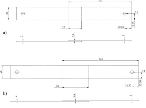
The specimens manufactured for the experimental tests consisted of SLJ with two different over-laps, 25 mm and 50 mm. This is a well-studied geometry that is relatively simple to manufacture but can provide reliable results regarding the strength of an adhesive substrate combination. For both geometries, the adherends were similar with a thickness of 2 mm and a width of 25 mm, vary-ing only in length. The specimens’ geometry used is shown in Figure 1, representvary-ing the two overlap lengths manufactured.
Figure 1: SLJ specimen geometry (dimensions in mm). (a) 25 mm overlap, (b) 50 mm overlap.
The bondline thickness used was 0.2 mm, the optimum value of the adhesive thickness for an epoxy adhesive, since for higher values the bending moment increases the peeling stresses and compromis-es the joint strength.
the impact testing machine. Specimens of both overlap lengths were also tested under quasi-static conditions as reference.
The joint configurations were initially set by creating combinations with the four adhesives se-lected for this work (two low modulus adhesives and two high modulus adhesives). As the mixed adhesive concept consists in the use of a high modulus adhesive in the centre of the overlap com-bined with a low modulus for stress reduction at the ends of the overlap (as shown in Figure 2), four combinations could be formulated using this technique with the available adhesives.
Figure 2: Mixed adhesive joints configuration (not to scale).
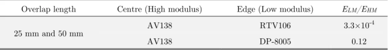
However, preliminary tests found that the curing temperature of the XNR6852E-2 adhesive (150ºC) was high enough to damage any other adhesive included in the same joint. Therefore, no mixed joint was made using this epoxy. The produced mixed joint configurations are shown in Ta-ble 3. The ELM/EHM ratio is also presented. This is the ratio between the modulus of the more flex-ible adhesive (ELM) and the modulus of the stiffer adhesive (EHM).
Overlap length Centre (High modulus) Edge (Low modulus) ELM/EHM
25 mm and 50 mm AV138 RTV106 3.3×10
-4
AV138 DP-8005 0.12
Table 3: Mixed adhesive joint configurations.
To serve as reference, single adhesive SLJs were also manufactured with all the adhesives pro-posed for this work. The specimens were tested both on static and impact conditions to compare the results and to explore possible improvements of joint strength. Another important parameter in the mixed adhesive joint geometry is the ratio between the surface areas occupied by each adhesive. The ratio selected used 1/3 of the bonding area occupied by the flexible adhesive and 2/3 of the area filled by the stiff adhesive. This ratio was already employed in a previous work [22], where good mixed joint mechanical properties were found. Joint manufacturing is also simplified using this ratio, as it avoids the bonding areas from becoming excessively small.
2.3 Specimen Manufacture
with 0.2 mm diameter. The line was fixed to the adherends with a small amount of cyanoacrylate based adhesive. After a proper surface preparation of the adherends, marks were drawn in the ad-herends with a permanent marker and a ruler to mark the location where the spacers should be placed. A mould, depicted in Figure 3, was used to align the specimens during the curing process, providing uniform pressure distribution.
Figure 3: Mould used to produce SLJ and its main components.
2.4 Static Tests
For static tests, the manufactured specimens were tested in a universal test machine INSTRON® model 3367 (Norwood, Massachusetts, USA), equipped with a load cell with a max capacity of 30 kN. The test consisted on a load application to the specimen in a longitudinal direction until failure, with a constant displacement rate of 1 mm/min (quasi-static) and under room temperature condi-tions. The load and displacement values were recorded, allowing the determination of various prop-erties of the specimen such as the elastic modulus and the maximum load and displacement at fail-ure. All of the manufactured combinations were tested (mixed and single adhesive joints) with both 25 mm and 50 mm overlaps. Four specimens of each configuration were tested.
2.5 Impact Tests
3 RESULTS
3.1 Static Tensile Test Results
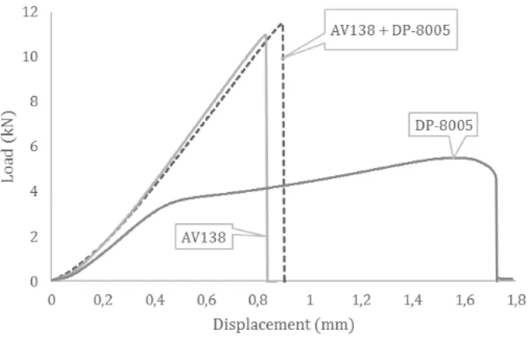
Tensile tests were performed on the SLJ specimens with various joint configurations. Figure 4 shows representative load-displacement curves of these tests for specimens with 25 mm of overlap length.
Figure 4: Typical load-displacement curves for all of the tested specimens with high strength steel adherends, 25 mm overlap.
Figure 5 shows representative load-displacement curves for SLJ specimens with 50 mm of over-lap.
Figure 6 presents a comparison between failure load values for the tensile tests of all joint con-figurations and substrates with both 25 mm and 50 mm overlap lengths.
Figure 6: Average maximum load for the joint combinations tested. 25 mm versus 50 mm.
The maximum strength was obtained by using a single application of the XNR6852E-2 adhe-sive, achieving a maximum load of around 19 kN average. The RTV106 and AV138 mixed configu-ration exhibited a maximum strength reduction when combined together, around 20% lower than when using only AV138. In addition, an improvement of joint strength was found by placing the adhesive DP-8005 on the same overlap of AV138 was found, as shown in Figure 7.
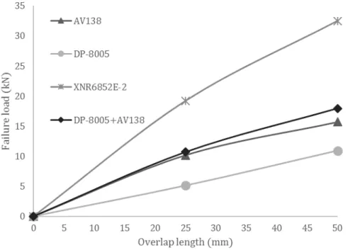
Figure 8 shows the failure load in function with the overlap length for the tested configurations, both for 25 mm and 50 mm overlap.
Figure 8: Failure load as a function of the overlap length for different adhesive combinations.
As seen in Figure 8, the variation of the overlap resulted in double joint strength for specimens with only DP-8005. Due to the ductility of this adhesive, the joint strength was almost proportional to the overlap length. The adhesive deformed plastically and, as the load increased, its deformation redistributed the stresses. On the other hand, a strength increase of only around 54% was found when doubling the overlap of the joint with AV138. In this case, the joint strength was not propor-tional to the overlap length. This can be justified with the fact that the stress concentration is al-ways at the ends of the overlap and increasing its length does not vary the stress distribution. The same occurred to the XNR6852E-2 but the increase in joint strength was around 69%, caused by the higher ductility of the adhesive.
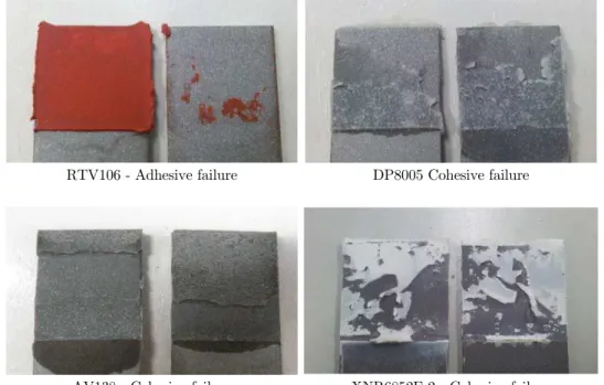
Single adhesive application
RTV106 - Adhesive failure DP8005 Cohesive failure
AV138 - Cohesive failure XNR6852E-2 - Cohesive failure
Mixed adhesive application
Adhesive failure for RTV106 Cohesive failure for AV138
Cohesive failure for DP8005 Cohesive failure for AV138
Figure 9: Failure modes for all of the tested joint configurations with high strength steel, 25 mm overlap.
Figure 10 shows the various fracture surfaces of the 50 mm overlap specimens.
The fracture surfaces did not show any dependency on the overlap length. For both overlap lengths, cohesive failure was verified for joints containing AV138, DP-8005 and XNR6852E-2. As for the joints with RTV106, the same adhesion problems were found as well for the mixed adhesive configuration of DP-8005 with XNR6852E-2, exhibiting once again a failure surface with mixed cohesive and interfacial failure for both adhesives.
Single adhesive application
DP8005- Cohesive failure AV138 - Cohesive failure
XNR6852E-2 - Cohesive failure
Mixed adhesive application
Cohesive failure for DP8005 Cohesive failure for AV138
Figure 10: Failure modes for all of the tested joint configurations with high strength steel, 50 mm overlap.
3.2 Impact Test Results
Figure 11: Average maximum load for the joint combinations tested under impact.
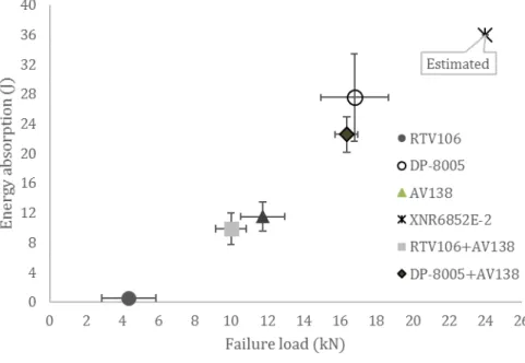
Figure 12: Energy absorption as a function of the average failure load.
lowest peak load and the very low energy absorption. Furthermore, when combined with the AV138 stiff adhesive, the joint strength was also reduced as in the static tests, once again providing no improvements under impact conditions.
A considerable strength improvement was found by combining DP-8005 with AV138. Using this configuration, the impact strength was improved by almost 40%, which turned a very brittle joint into a good candidate for service under impact, exhibiting good behaviour and high values of energy absorption. As for the joint containing only XNR6852E-2, similarly to the static tests it exhibited the highest maximum load, making it a good adhesive for both conditions, without significant strain-rate dependency due to the additional flexibility that it offers. The energy absorption was also the highest with this configuration.
However, due to imposed limitations on the specimens fixing mechanism of the impact machine, it was not possible to fully test this configuration, as the fixing screws securing the specimen in place always broke at the time of impact. Therefore, the results shown for this configuration refer to the load and energy necessary to break the screw, and not for breaking the adhesive bond itself. The conclusion can be drawn that at least 18 kN can be handled by the adhesive in impact condi-tions for a SLJ with an overlap of 25 mm without failure and an energy of at least 32 J can be ab-sorbed.
In order to obtain an estimate of the actual failure load of this joint, three 12.5 mm overlap specimens were produced and tested under the same conditions. For this case the applied energy was able to break the smaller overlap joint. The tested specimens exhibited an average maximum load of 14.27 kN with a standard deviation of 0.82 kN.
The average energy absorption of the specimens was 19.5 J with a standard deviation of 4.3 J. Given this, a simple prediction of the maximum impact load for a 25 mm overlap can be done con-sidering the overlap influence data of the quasi-static tests. For this purpose, a minor strain-rate dependency needs also to be considered, which cannot be completely true, but it is only intended to represent a small comparison, so as a simple estimation it is sufficient. In quasi-static tests, when doubling the overlap from 25 mm to 50 mm the joint strength was increased by 70%. Using the same proportionality, a 25 mm overlap joint under impact conditions should handle an estimated 24 kN for the maximum load and absorb an energy of 36 J.
Generally, the energy values followed the same trend of the failure load values. Higher energy values were found for higher failure loads and the lowest energies were found for lower failure loads. A large improvement was found by using the combination of DP-8005 with AV138, showing around 100% increase in energy absorption compared to the energy absorbed by a configuration of only AV138. This proves the capabilities of the mixed adhesive technique to improve behaviour under impact loads.
Single adhesive application
RTV106 - Adhesive failure DP-8005 - Cohesive failure
AV138 - Cohesive failure XNR6852E-2 - Cohesive failure
Mixed adhesive application
Adhesive failure for RTV106 Cohesive failure for AV138
Cohesive failure for AV138
Cohesive failure for DP8005
Figure 13: Failure modes for all of the tested joint configurations with high strength steel, 25 mm overlap.
The failure modes revealed almost no differences from the behaviour found in static tests. Cohe-sive failure was found in joints containing AV138, DP-8005 and XNR6852E-2. For the RTV106, the same adhesion problems were found also in impact. In addition, similarly to the static conditions, there was no plastic deformation of the adherends.
3.3 Comparison Between Static and Impact Results
Figure 14: Average maximum load comparison between static and impact conditions.
Generally, the ductile joint configurations were those that exhibited greater variation between both testing conditions, reinforcing the idea that the flexibility of the adhesives is a good character-istic for impact conditions. In the case of the RTV106 joints, the impact load was six times higher than the load necessary to break the bond in static conditions, even with the before mentioned ad-hesion problems. The joints with DP-8005 adhesive also revealed high strain-rate dependency due to some viscoelasticity. This joint achieved a failure load of almost 17 kN in impact conditions while it only provided 5 kN of failure load in static tests. The main reason for such results are the high flex-ibility and energy absorption capabilities of this adhesive. On the other hand, the AV138 joints exhibited 16% higher values than in static tests. This was expected due to its high stiffness, which makes it a poor choice for impact operations when used alone. Even the addition of silicone to the overlap, the joint did not show great variation compared to the static results, as most of the strength is provided by the stiff adhesive. A small gain was found when combining both adhesives, but it was very slight. However, the configuration of DP-8005 with AV138 provided once again good results. By comparing the results from both test conditions, it is noticeable that the use of the acrylic adhesive (DP-8005) increased the joint flexibility, reaching a variation in joint strength at impact of around 50% more compared to the static conditions.
Figure 15: Average maximum load comparison between static and impact conditions for joints with DP-8005 and AV138.
By combining both adhesives, the static strength of AV138 was retained (and even slightly im-proved) while the impact strength of the DP-8005 adhesive was retained. This combination thereby combines the best of both worlds. This configuration can be a good choice for the automotive indus-try, combining stiffness and strength for the regular operating conditions, but also providing strength under impact in the case of an accident.
These results demonstrate that the mixed adhesive technique has the capability to improve joint strength of adhesive joints subjected to impact loadings, especially when the technique is ap-plied to a brittle adhesive. The flexibility of the joint is increased, resulting in better energy absorp-tion capacity without failing, which is a fundamental characteristic for good behaviour under im-pact conditions.
4 CONCLUSIONS
This work undertook a study of various mixed joints configuration under static and impact condi-tions. For this purpose, a new experimental technique was developed to manufacture SLJ with mixed adhesive layers with a minimum amount of defects. In accordance with the results of previ-ous research, the use of a ductile adhesive at the ends of the overlap combined with a brittle adhe-sive, such as the combination of DP-8005 and AV138, improves the maximum strength of the joints in quasi-static tests. Not only was the maximum strength improved but also the extension at fail-ure. The tests also demonstrated that the effectivity of the mixed adhesive technique increases with the use of longer overlaps, especially when a ductile adhesive is combined with a very stiff one.
the mixed adhesive combination exhibited an 100% increase in energy absorption compared to the energy absorbed by a configuration of only AV138, proving the capabilities of the mixed adhesive technique in impact situations, especially when it is applied with brittle adhesives. The joint config-urations with ductile adhesives were those that exhibited greater variation between static and im-pact testing conditions, reinforcing the idea that the flexibility of the adhesives is a good character-istic for impact conditions. As an example, the DP-8005 adhesive revealed very high strain-rate dependency.
Overall, the best joint configuration for both static and impact conditions was proven to be the single application of the crash resistance adhesive XNR6852E-2. Mixed adhesive joints using this adhesive could possibly yield even higher performance but the high curing temperature of the XNR6852E-2 made their manufacture impossible.
References
Adams R.D., Harris J.A. (1985). An assessment of the impact performance of bonded joints for use in high energy absorbing structures, Journal of Mechanical Engineering Science 199(2): 121-131.
Adams R.D. (2005) Adhesive bonding, science, technology and applications. Woodhead Publishing Limited, (Cam-bridge).
Breto R., Chiminelli A., Duvivier E., Lizaranzu M., Jiménez M. A. (2015) Finite element analysis of functionally graded bond-lines for metal/composite joints, Journal of Adhesion 91(12): 920-936.
da Silva L.F.M, da Silva R.A.M., Chousal J.A.G. and Pinto A.M.G. (2008) Alternative methods to measure the adhesive shear displacement in the thick adherend shear test, Journal of Adhesion Science and Technology 22(1): 15-29.
da Silva L.F.M., Adams R.D. (2007) Adhesive joints at high and low temperatures using similar and dissimilar ad-herends and dual adhesives, International Journal of Adhesion and Adhesives 27(3): 216-226.
da Silva L.F.M., de Magalhães F.A.C.R.G., Chaves F.J. P. and de Moura M.F.S.F. (2010) Mode II fracture tough-ness of a brittle and a ductile adhesive as a function of the adhesive thicktough-ness, Journal of Adhesion 86(9): 891-905. da Silva L.F.M., Lopes M.J.C.Q. (2009) Joint strength optimization by the mixed adhesive technique, International Journal of Adhesion and Adhesives 29(5): 509-514.
da Silva L.F.M., Öchsner A., Adams R.D. (2011a) Handbook of adhesion technology, 1st ed., Springer (Berlin). da Silva L.F.M., Pirondi A., Öchsner A. (2011b) Hybrid Adhesive Joints, Springer (Berlin).
de Barros S., Champaney L. and Valoroso N. (2012). Numerical simulation of crack propagation tests in adhesive bonded joints. Latin American Journal of Solids and Structures 9(2012): 339-351.
Dey S., Adhikari S. and Karmakar A. (2015). Impact response of functionally graded conical shells. Latin American Journal of Solids and Structures 12(2015): 133-152.
Fitton M.D., Broughton J.G. (2005) Variable modulus adhesives: an approach to optimized joint performance. Inter-national Journal of Adhesion and Adhesives; 25(4): 329-336.
Goda Y., Sawa T. (2011) Study on the effect of strain rate of adhesive material on the stress state in adhesive joints, Journal of Adhesion 87(7-8): 766-779.
Goglio L., Rossetto M. (2008) Impact rupture of structural adhesive joints under different stress combinations, Inter-national Journal of Impact Engineering 35(7): 635-643.
Hart-Smith L.J. (1973) Adhesive-Bonded Double Lap Joints, Nasa Contract Report, CR-112235.
Loureiro A. L., da Silva L. F. M., Sato C., Figueiredo M. A. V. (2010) Comparison of the mechanical behaviour between stiff and flexible adhesive joints for the automotive industry, Journal of Adhesion 86(7): 756-787.
Marques E.A.S., Banea M.D., da Silva L.F.M., Carbas R.J.C., Sato C. (2016) Effect of low temperature on tensile strength and mode I fracture energy of a room temperature vulcanizing silicone adhesive, Journal of Testing and Evaluation DOI: 10.1520/JTE20140208.
Marques E.A.S., Magalhães D.N.M., da Silva L.F.M. (2011) Experimental study of silicone-epoxy dual adhesive joints for high temperature aerospace applications, Materialwissenschaft und Werkstofftechnik 42(5): 471-477. Pethrick R. (2015) Design and ageing of adhesives for structural adhesive bonding – A review, Journal of Materials: Design and Applications 229(5): 349-379.
Pinto A.M.G., Magalhães A.G., Campilho R.D.S.G., de Moura M.F.S.F. and Baptista A.P.M. (2009) Single-lap joints of similar and dissimilar adherends bonded with an acrylic adhesive, Journal of Adhesion 85(6): 351-376. Raphael C. (1966) Variable adhesive bonded joints, Applied Polymer Symposia 3: 99-108.
Sato C., Ikegami K. (2000) Dynamic deformation of lap joints and scarf joints under impact loads. International Journal of Adhesion and Adhesives 20(1): 17–25.