T
he
B
ending and
S
hear
B
ehaviour of
L
aminar
S
tructures of
H
igh
P
erformance
F
ibre
R
einforced
C
oncrete
Simão Pedro Fonseca Santos
School of Engineering
Dept. of Civil Engineering
University of Minho
Guimarães, Portugal
_________________________________________________________________________ Supervisor: Joaquim António Oliveira de Barros
ii
“THE BENDING AND SHEAR BEHAVIOUR OF LAMINAR STRUCTURES OF HIGH
PERFORMANCE STEEL FIBRE REINFORCED CONCRETE”
Prégaia – Sociedade de Pré-Fabricação, S.A. CiviTest - Pesquisa de novos materiais para a Engenharia Civil, L.da
Departamento de Engenharia Civil da Escola de Engenharia
Universidade do Minho
iii
The author would like to thank the following institutions:
FCT – Fundação para a Ciência e a Tecnologia; ADI – Agência de Inovação; BEKAERT; Degussa Chemicals Portugal; COMITAL – Companhia Mineira de Talcos, SA; SECIL – Companhia geral de cal e cimento, SA; DuroEuropa – Produtos Endurecedores, Lda; Marques e Cruz, Lda and FibreSensing.
iv
To my Grandfathers memory To you, Mara
v Ao Professor Doutor Joaquim Barros, orientador científico deste trabalho: pelo empenho e rigor com que abraça os seus projectos, pela motivação que incute em quem com ele colabora; pelo inconformismo em relação ao medíocre, pela exigência presente em cada minuto; por ter sido, sempre, incansável demonstrador do valor do trabalho no enriquecimento profissional e pessoal; pela oportunidade que tenho tido de privar com ele como amigo. Um grande bem-haja!
Aos amigos da Universidade do Minho, colegas, professores, funcionários do laboratório: pela forma como me receberam e me ajudaram desde o primeiro dia; pela partilha de muitos momentos, pelos debates de ideias em ambiente de tertúlia.
Às empresas Civitest, Duro-Europa, Maprel, Pisonort e Prégaia, e respectivos funcionários, pela disponibilidade das instalações e meios necessários à realização dos programas experimentais.
À Hilti Española S.A., nas pessoas do Responsável do Departamento de Engenharia, Alejandro Alvarez e do Director Geral em fiunções até Dezembro de 2007, Juan Zaballos: pela confiança que tiveram em mim ao contratar-me, sabendo que estava a braços com a presente Tese apoiando-me em todos os sentidos; pela amizade.
Aos meus Amigos de sempre, pela confiança que me transmitem ao acreditarem em mim.
À minha família e à família da Mara (que também é minha): por toda a estabilidade emocional que me têm proporcionado., factor preponderante para poder estar sempre à altura dos desafios que se me colocam.
À Mara: companheira de absolutamente todos os momentos, os bons e os menos bons; pela partilha de todas as etapas que temos vindo a atravessar ao longo dos anos; pela inteligência que aplica em todos os actos, pela força e ambição que transmite; por saber sempre maximizar o tempo em que estamos juntos, minimizando os efeitos da distância física que nos separa.
vi The concrete precasting industry is frequently requested to produce structural elements of reinforced concrete with high geometric complexity. These geometric conditions introduce difficulties on the placement of reinforcement, resulting in a large consuming time phase of the industrial process, causing delays in the construction schedule. Moreover, when high percentage of reinforcement is used, there are difficulties on assuring the desired concrete pouring quality, once the compaction process may be very difficult to execute, although all the great advances in compaction techniques and equipments. Most of the times, in these conditions and in the absence of rigorous quality control and specialized workers, the elements present deficiencies that can compromise the mechanical behaviour and the visual appearance of the final structure.
Self-compacting concrete (SCC) can be defined as concrete that is able to flow in the interior of the formwork, passing through the reinforcement and filling it in a natural manner, being consolidated under the action of its own weight. Adding the benefits of SCC to those resulting from the addition of discrete fibres to cement based materials, a high performance material, designated by steel fibre reinforced self-compacting concrete (SFRSCC), is obtained. Steel fibre reinforcement greatly increases ductility of concrete, retards crack coalescence and propagation, increases pronouncedly the after-cracking energy absorption and decreases the width of the cracks.
Although all the advantages already known and recognized, the technology of Steel Fibre Reinforced Concrete (SFRC) still deserving a certain rejection from structural engineers solutions: not only to applications that involve safety considerations but also where the fibres are used as secondary reinforcement.
In the present work, an evaluation of the bending and shear behaviour of laminar structures in high performance steel fibre reinforced concrete (HPSFRC) will be carried out. Two wide research programs were developed in order to find out the influence of steel fibres reinforcement in the mechanical behaviour of these structures. The influence of the strength class, fck, in the load
carrying capacity and its influence in the reinforcing mechanisms that steel fibres can develop within a composition of HPSFRC were also studied. The performance of the analytical approach for the prediction of the fibre reinforcement contribution in terms of shear resistance of concrete beams
vii the crack shear sliding.
The experimental programs and the numerical research are described, and the main results are presented and discussed.
viii
R
ESUMO
A indústria de pré-fabricados de betão depara-se, frequentemente, com a necessidade de produzir elementos estruturais de elevada complexidade geométrica. Essa complexidade geométrica dificulta significativamente a introdução das armaduras de reforço nas cofragens, o que aumenta consideravelmente o tempo de produção das peças podendo, inclusivamente, ser causadora de atrasos no processo de fabricação. Ademais, quando a percentagem de armadura é elevada, existe uma maior dificuldade em garantir a qualidade de betonagem desejada, uma vez que a operação de vibração pode tornar-se numa tarefa árdua ou mesmo impossível, apesar de todos os avanços que vêm conhecendo a tecnologia e os equipamentos de vibração ao longo dos últimos anos. Na maior parte das vezes, nestas condições, e na falta de um controlo de qualidade rigoroso, bem como de mão-de-obra especializada, os elementos pré-fabricados apresentam deficiências que podem comprometer o comportamento mecânico e a aparência da estrutura final.
O betão auto-compactável (BAC) pode ser definido como sendo um material capaz de fluir no interior da cofragem e de passar através da armadura, unicamente sob acção do seu peso próprio, ou seja, sem vibração. Conjugando as vantagens do betão auto-compactável com as que advêm da adição de fibras a materiais de matriz cimentícia, obtém-se um material com desempenho elevado, designado de betão auto-compactável reforçado com fibras de aço (BACRFA). A utilização de fibras de aço aumenta a ductilidade do betão, retarda ao aparecimento e a propagação de fendas, aumenta significativamente a absorção de energia na fase pós-fendilhada e reduz a largura de fendas.
Apesar de todas as vantagens já reconhecidas, a tecnologia do Betão Reforçado com Fibras de Aço continua a ser alvo de alguma rejeição por parte dos engenheiros de estruturas, à hora de a eleger como solução estrutural: não apenas em aplicações de alta responsabilidade do ponto de vista estrutural mas também em aplicações em que as fibras de aço são usadas como reforço secundário.
No presente trabalho é feita uma avaliação do comportamento à flexão e ao corte de estruturas laminares de betão de elevado desempenho reforçado com fibras de aço (BEDRFA).
ix bem como a sua influência nos mecanismos que as fibras podem desenvolver dentro de uma composição de BEDRFA. Foi avaliado o modelo analítico para a previsão da contribuição das fibras de aço no reforço ao corte de vigas de betão proposto pelo RILEM TC 162 TDF. Foi levada a cabo a simulação numérica dos ensaios realizados com vigas de betão de alta resistência reforçado com fibras de aço (BARRFA), simulação esta realizada através de uma análise não-linear material com o método dos elementos finitos, utilizando uma lei de amolecimento para modelar o desenvolvimento das fendas de corte.
No presente trabalho é feita uma descrição dos programas experimentais realizados; os principais resultados serão apresentados e discutidos.
x
R
ESUMEN
La industria del la prefabricación se depara, muchas veces, con la necesidad de producir elementos estructurales de elevada complejidad geométrica. Esa complejidad dificulta significativamente la introducción de las armaduras de refuerzo en los encofrados, aumentando considerablemente el tiempo de producción de las piezas pudendo, incluso, ser la causa de retrasos en el proceso de fabricación. Además, cuando el porcentaje de armadura es elevado, existe una mayor dificultad en garantizar la calidad del hormigonado, ya que la vibración puede ser una tarea complicada o hasta imposible, a pesar de todos los avances en la tecnología y los equipos de vibración a lo largo de los últimos años. En la mayor parte de las veces, en estas circunstancias y, en la falta de un control de calidad riguroso bien como de mano de obra especializada, los elementos prefabricados presentan defectos que pueden comprometer su comportamiento mecánico y la apariencia de la estructura final.
El hormigón auto compactante (HAC) puede definirse como un material con la capacidad de fluir en el interior del encofrado y de pasar a través de las armaduras, únicamente bajo la acción de su peso propio, es decir, sin vibración. Conjugando las ventajas del hormigón auto compactante con las ventajas de la adición de fibras a materiales de matriz cementicia, se obtiene un material con elevado desempeño, que se designa de hormigón auto compactante reforzado con fibras de acero (HACRFA). La utilización de fibras de acero aumenta la ductilidad del hormigón, retrasa el aparecimiento y la propagación de grietas, aumenta de forma significativa la absorción de energía en la fase pos fisurada y reduce el ancho de las grietas.
No obstante todas las ventajas ya conocidas, la tecnología del hormigón reforzado con fibras de acero sigue sin gran aceptación por parte de los ingenieros de estructuras, a la hora de elegirla como solución estructural: no solo en aplicaciones de alta responsabilidad del punto de vista estructural sino en aplicaciones en las cuales las fibras de acero se usan como refuerzo secundario.
En el presente trabajo se hace una evaluación del comportamiento en flexión y a cortante de estructuras laminares de hormigones de elevado desempeño reforzados con fibras de acero
xi capacidad de carga de los elementos, bien como su influencia en los mecanismos que las fibras pueden desarrollar dentro de una composición de HEDRFA. Se hizo la evaluación del modelo analítico propuesto por el RILEM TC 162 TDF para la previsión de la contribución de las fibras de acero en el refuerzo a cortante de vigas de hormigón. Se ha llevado a cabo la simulación numérica de los ensayos realizados con vigas de hormigón de alta resistencia reforzado con fibras de acero, simulación hecha con recurso a un análisis no-lineal material con el método de los elementos finitos, utilizando una ley de softening para modelizar la propagación de las grietas de cortante.
En el presente trabajo se hace una descripción de los programas experimentales realizados; los principales resultados serán presentados y discutidos.
xii
C
Acknowledgements ... v ABSTRACT ... vi RESUMO ... viii 1.Introduction ... 11.1. Background, aim and scope ... 1
1.2. Outline of contents ... 3
2.Steel Fibre Self Compacting Concrete technology ... 5
2.1. Definition of Self Compacting Concrete ... 5
2.2. Tests to assess self-compacting requirements ... 7
2.2.1. Slump Flow Test ... 7
2.2.2. L-Box Test ... 9
2.2.3. U-Box Test ... 11
2.2.4. V-Funnel Test ... 12
2.2.5. Orimet Test ... 13
2.3. The possibilities of steel-fibre reinforced concrete: an overview ... 14
2.4. Conclusions ... 15
3.Façade panels in steel fibre self-compacting concrete... 17
3.1. Introduction ... 17
3.2. Material constituents ... 19
3.3. Mix design method for self-compacting concrete admixtures ... 20
3.4. Material Properties ... 21
3.4.1. Compression ... 21
3.4.2. Bending ... 26
3.4.3. Conclusions ... 31
3.5. Development of a composition of SFRSCC with 45kg/m3 of steel fibres ... 32
3.6. Structural Properties ... 40
3.6.1. Flexural Behavior of Panel Prototypes ... 40
3.6.2. Punching behaviour of panel prototypes ... 44
3.7. Manufacture and testing a real scale façade panel ... 48
xiii
4.2.1. Test series ... 60
4.2.2. Mix compositions ... 61
4.2.3. Test set up and monitoring system ... 62
4.3. Results and analysis ... 63
4.4. Fibre Distribution ... 67
4.5. Design Strategy Approach ... 68
4.6. Numerical Simulation ... 70
4.7. Conclusions ... 72
5.High performance fibre reinforced concrete elements failing in shear ... 74
5.1. Motivation ... 74
5.2. Fibrous reinforcing systems for the shear resistance of concrete elements: an overview .. 76
5.3. Experimental program ... 78
5.3.1. Test series ... 79
5.3.2. Mix Compositions ... 80
5.3.3. Test set up and monitoring system ... 82
5.4. Results and analysis ... 84
5.5. Failure modes ... 88
5.6. Influence of Steel Fibres in Shear Reinforcement ... 88
5.7. Numerical Strategy ... 92
5.7.1. Introduction ... 92
5.7.2. Inverse Analysis ... 94
5.7.3. Simulations of the slabs’ tests ... 96
5.8. Conclusions ... 98
6.Conclusions and future work ... 99
6.1. Introduction ... 99
6.2. Main conclusions ... 99
6.2.1. Steel fibre reinforced self-compacting concrete for façade elements ... 99
6.2.2. Steel fibre reinforced self-compacting concrete for elements failing in bending ... 100
6.2.3. Fibre reinforced concrete for elements failing in shear ... 100
6.2.4. Numerical strategies ... 101
xv
Figure 2.1: Flow Test Apparatus: a) representation; b) real apparatus ... 8
Figure 2.2: Measuring the final diameter of SFRSCC in one direction ... 8
Figure 2.3: Abrams Cone with J-Ring Slump Flow Test Apparatus: a) representation; b) real apparatus ... 9
Figure 2.4: L-Box test apparatus: a) representation; b) real apparatus ... 10
Figure 2.5: End of test ... 11
Figure 2.6: Measuring H2 ... 11
Figure 2.7: Measuring H1 ... 11
Figure 2.8: U-Box test apparatus ... 12
Figure 2.9: V-Funnel test apparatus: a) representation; b) real apparatus ... 13
Figure 2.10: Orimet Test Apparatus with J-Ring ... 14
Figure 3.1: Test setup to evaluate the concrete Young’s Modulus, Ec ... 22
Figure 3.2: Representation of load cycles to determine Ec ... 22
Figure 3.3: Configuration of compression test and position of the LVDT’s ... 23
Figure 3.4: Stress-strain curves of SFRCSCC of different ages. ... 24
Figure 3.5: Evaluation of the applicability of CEB-FIP 1993 expressions to simulate the behaviour of SFRSCC ... 24
Figure 3.6: Variation of fcm with age. ... 25
Figure 3.7: Variation of Ecm with age. ... 25
Figure 3.8: Bending Test Setup ... 27
Figure 3.9: Normal Load-Displacement relation in a bending test ... 28
Figure 3.10: Assumed stress distribution in the beam cross section ... 29
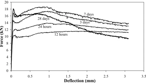
Figure 3.11: Load-deflection curves for SFRSCC of different ages ... 30
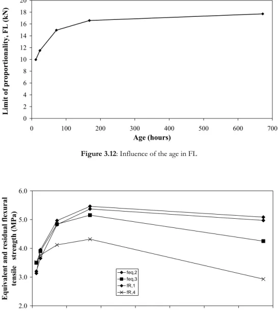
Figure 3.12: Influence of the age in FL ... 31
Figure 3.13: Influence of the age in equivalent and residual flexural strength parameters. ... 31
Figure 3.14: Variation of Ecm with age ... 34
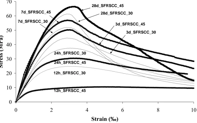
Figure 3.15: Influence of the age on the stress-strain response of SFRSCC_30 and SFRSCC_45 ... 35
Figure 3.16: Influence of the age on the fcm of SFRSCC_30 and SFRSCC_45 ... 35
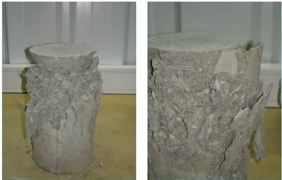
Figure 3.17: Typical failure mode of compression tests ... 36
xvi
Figure 3.22: Geometry of panel prototype ... 40
Figure 3.23: Metallic formwork to build the panel and disposition of the lightweight elements ... 41
Figure 3.24: Formwork detail ... 41
Figure 3.25: Filling the panel ... 41
Figure 3.26: Panel after have been cast ... 41
Figure 3.27: Test setup ... 42
Figure 3.28: Supports of the panel prototype ... 42
Figure 3.29: Position of the loading points ... 42
Figure 3.30: Position of the LVDTs to measure the panel deflection ... 42
Figure 3.31: Panel prototype being tested in bending ... 43
Figure 3.32: Load-deflection curve for each LVDTs of the SFRSCC_30 panel ... 43
Figure 3.33: Load-deflection curve for each LVDTs of the SFRSCC_45 panel ... 43
Figure 3.34: Crack pattern in SFRSCC_30, at the end of the bending test ... 44
Figure 3.35: Crack pattern in SFRSCC_45, at the end of the bending test ... 44
Figure 3.36: Punching test apparatus: a) General view representation; b) Detail view of the real test ... 44
Figure 3.37: Punching test specimens (all measures in mm): a) Overview representation; b) Cut view ... 45
Figure 3.38: Load-displacement relationship up to of about a) 20 mm and b) 4 mm, from punching test in a SFRSCC_30 panel ... 45
Figure 3.39: Load-displacement relationship up to of about a) 20 mm and b) 4 mm, from punching test in a SFRSCC_45 panel ... 46
Figure 3.40: a) Punching critical contour and yield line due to negative moments (exterior contour); b) Failure surface in a punching test ... 46
Figure 3.41: Panel Geometry (dimensions in mm) ... 49
Figure 3.42: Placing the lightweight elements ... 50
Figure 3.43: Heavy beam to assure stability of the lightweight elements during concrete casting ... 50
Figure 3.44: Casting operations of the panel ... 50
Figure 3.45: Demoulding panel operations ... 51
xvii
Figure 3.49: LVDT for measuring the panel deflection at its center ... 53
Figure 3.50: Placing the concrete plates to simulate the panel live load ... 53
Figure 3.51: Final view of the panel, loaded with 33 concrete plates ... 54
Figure 3.52: Crack opening profile of the critical crack ... 54
Figure 4.1: Longitudinal and transversal cross sections of the tested slab strips ... 60
Figure 4.2: Apparatus of 4 point loading tests in slab strips including monitoring system: a) Scheme; b) Real test performing ... 63
Figure 4.3: Load-central deflection curves of series L_6. ... 66
Figure 4.4: Load-central deflection curves of series L_8. ... 66
Figure 4.5: Load-central deflection curves of series L_10. ... 66
Figure 4.6: Relationship between the midspan deflection and the relative increment of the slab load carrying capacity for all series. ... 66
Figure 4.7: Locations of the core samples extracted. ... 67
Figure 4.8 - Fibre distribution along the depth of the slab. ... 68
Figure 4.9: Stress-Strain diagram used in the numerical strategy ... 71
Figure 5.1: Materials used in HPSFRC compositions: a) Coarse Aggregate 2 (14/20); b) Coarse Aggregate 1 (6/14); c) Fine Aggregate (2/6); d) Fine Sand; e) Limestone Filler (máx: 10µm); f) Type II, 42.5R Cement; ... 81
Figure 5.2: Ordinary reinforcement: a) longitudinal view; b) transversal view ... 83
Figure 5.3: Three point loading tests in slab strips: a) general view; b) monitoring system ... 83
Figure 5.4: Stress-strain curves of HPSFRC: a) fcm50 series; b) fcm70 series ... 84
Figure 5.5: Notch in a specimen to evaluate bending parameters of HPSFRC: depth = 74mm ... 85
Figure 5.6: Load-displacement curves of bending in the tested series of HPSFRC: a) fcm50 series; b) fcm70 series ... 86
Figure 5.7: Load-displacement curves series with ordinary longitudinal reinforcement ... 87
Figure 5.8: Crack Pattern in fcm50 series: a) without fibres, b) 60 kg/m3 and c) 75 kg/m3 of fibres . 88 Figure 5.9: Tri-linear normal stress - normal strain diagram to simulate the fracture mode I crack propagation ... 92
Figure 5.10: Bi-linear shear stress-shear strain diagram to simulate the fracture mode II crack sliding. ... 93
xviii
experimental and inverse analysis results ... 95
Figure 5.15: Relationships between the load and the displacement at the midspan ... 97
Figure 6.1: Prestressed Delta beam in HSSFRC ... 102
xix
Table 2.1: Times of execution and implication of worker ... 15
Table 3.1: Final Composition for 1 m3 of SFRSCC 30 kg of fibres ... 21
Table 3.2: Final composition to 1 m3 of SFRSCC_30 compared with SFRSCC_45 ... 33
Table 4.1: Adopted composition (per m3 of concrete) ... 62
Table 4.2: Main characteristics of the tested slab strips. ... 64
Table 4.3: Force values of the tested slabs. ... 65
Table 4.4: Increase provided by fibre reinforcement in terms of load carrying capacity at serviceability (IF(ELUt)) and ultimate limit states (IF(Max)). ... 67
Table 4.5: Influence of the content of fibres on the flexural resistance. ... 69
Table 4.6: Equivalence between a cross section area of a fictitious conventional reinforcement and a content of steel fibres. ... 70
Table 4.7: Concrete properties.‰ ... 71
Table 5.1: Compositions of HSC designed to the experimental program. ... 79
Table 5.2: Compositions of HPC designed to the experimental program (per m3 of concrete) ... 82
Table 5.3: Relation of the slab strips built and tested ... 82
Table 5.4: Mechanical characterization of the tested series: compression tests ... 84
Table 5.5: Values for the FELUt and Fmax ... 87
Table 5.6: Fibre reinforcement effectiveness indexes for serviceability (IF(ELUt)) and ultimate (IF(Max)) limit state analysis ... 88
Table 5.7: Contribution of steel fibres to the concrete shear resistance ... 91
Table 5.8: Values of the parameters derived from inverse analysis ... 96
Table 5.9: Values of the parameters used in the first intent of simulation………97
Simão Pedro Fonseca Santos – University of Minho, Portugal 1-119
1.
I
NTRODUCTION
1.1. Background, aim and scope
Since every time, the idea of excellent performance and constant superseding of the limits moves all society agents, enhancing all types of technology, developing all variants of knowledge.
The concrete issues and all the industries related are not an exception. Concrete has been in existence in changing forms for thousands of years (Pereira, 2006) (to a detailed description of concrete history, see Smeaton (1813), le Châtelier (1904), Vitruvius (1931), Gimpel (1967), Efstathiadis (1978), Stanley (1979) and Idorn (1997)). However, the real development of concrete technology started in the early 19th century, when Joseph Aspdin made a new, improved cement by
heating chalk and clay together, and then grinding it down to fine powder. It was the naissance of the Portland cement, a material that would revolutionize the modern world, allowing the construction of cities, countries, civilizations. It was a clear example of superseding.
The development of concrete compositions designed to set special requirements (ductility, ease of placement, compaction without segregation, early age strength, long-term mechanical properties, permeability, density, heat of hydration, toughness, volume stability, long life in severe environments, etc.) started much later. Only in 1970, the first fibre reinforced concrete building was constructed; five years later the highest reinforced concrete building was constructed: the CN Tower in Toronto, Canada (555 meters), the tallest slip-form building to date. The fundamental benefit of incorporating fibres in concrete is the increase in toughness which, in the context of fibre reinforced concrete (FRC), is a broad term that is used to represent the increase in the energy dissipation during the loading process. This is reflected by the ability of the material to ensure cracking without disintegrating completely, as in plain unreinforced concrete. In structural applications, such
Simão Pedro Fonseca Santos – University of Minho, Portugal 2-119
behaviour could result in significant advantages against impact loads, seismic actions, shrinkage and splitting and shear forces (Oliveira e Sousa and Gettu, 2004).
The development of self-compacting concrete started even later, in 1988, in Japan (Okamura and Ozawa, 1994). The problem of the durability and applicability of concrete in structures was a major topic of interest in this country. The durability of concrete is intimately related to the level of compaction achieved while concreting, and the gradual reduction of skilled workers in Japan´s construction industry led to a reduction in the quality of construction work. Consequently, the development of a self-compacting concrete (SCC), able to be compacted purely by means of its own weight and without the need of any external vibration system, independently from the quality of the construction work, started to seem a good alternative to be developed.
The adventure of the so called High Performance Concretes (HPC) is a new concept, with around 40 years. Since then, researchers and society agents related with construction industry have done an effort to go deeper in the comprehension of these technologies, trying to understand the chemical and physical phenomena acting in structures built with such materials. Great efforts have been done, resulting in great achievements.
Although all the knowledge that already exists in the field of the HPC, the utilization of these kinds of compositions did not spread as it was expected by the most optimists. The lack of specific design codes and construction practices leads to a still insufficient development of this technology: designers do not have official normative to defend their calculations. This fact is appointed as the main reason for the present situation, but it is not the only reason.
In order to provide the designers with these kinds of tools, a great effort in recognizing all the possible phenomena related with HPC technology is needed. This means experimental results in a quantity that can justify the execution of normative; numerical models able to simulate these phenomena must be also developed. These data must be absorbed by the designers. The promoters must understand the great benefits and lower costs of this technology. A real change in the manufacturing processes using a new generation of concretes, means that all this parameters must be aligned in the same direction.
Beside all the non-technical reasons, there are also the technical ones. The bending and shear behaviour of laminar structures of High Performance Fibre Reinforced Concrete (HPFRC) is not
Simão Pedro Fonseca Santos – University of Minho, Portugal 3-119
already known in some very important aspects. The aim of the present work, based on an extensive experimental work and numerical simulations, is to understand the behaviour of HPFRC structural elements under bending and shear load conditions. An evaluation of some formulations to predict the failure of these elements is presented and discussed. A numerical strategy with a program based on the Finite Element Method (Femix) is carried out and an evaluation of its level of accuracy is done and discussed.
The work aims also to be a contribution to the development and the spread of the HPC technologies, serving as a tool to all the technical agents related with the construction industry areas where the utilization of these kinds of materials can be extremely useful. One final objective is to show that it is possible to design cost competitive compositions of HPC, discarding the idea that this kind of technology is very onerous.
1.2. Outline of contents
The different chapters of the thesis are briefly described in the following. The thesis consists in 6 chapters and an extensive bibliography.
In Chapter 2, a detailed review of the relevant aspects of steel fibre reinforced self-compacting concrete (SFRSCC) technology is given, including the principal properties, materials and mixture proportions, test methods for characterizing the material and an overview of some special applications.
In Chapter 3, a real scale application is presented. This work was part of a research project developed in a prefabrication industry whose interests are mainly related with the conception of façade panels for buildings. Specific compositions of SFRSCC were conceived and tested in laboratory. The structural behaviour of the material was characterized with resource to laboratory tests in panel prototypes. In order to assess the applicability of the conceived compositions, a real scale panel was fabricated and tested in industrial environment.
In Chapter 4, an experimental program to understand the behaviour of laminar structures of HPSFRC for laminar structures failing in bending is presented. The main target is to assess if and how can ordinary reinforcement be replaced by steel fibres.
Simão Pedro Fonseca Santos – University of Minho, Portugal 4-119
In Chapter 5, an introduction to High Strength Concrete (HSC) technology is presented. Several compositions of HPSFRC were developed. An experimental program was carried out to determine the contribution of steel fibres in HPSFRC elements failing in shear.
The general and specific conclusions of the Thesis are presented in Chapter 6, along with some recommendations for future research.
Simão Pedro Fonseca Santos – University of Minho, Portugal 5-119
2.
S
TEEL
F
IBRE
S
ELF
C
OMPACTING
C
ONCRETE
T
ECHNOLOGY
2.1. Definition of Self Compacting Concrete
Self-compacting concrete (SCC) can be defined as concrete that is able to flow in the interior of the formwork, passing through the reinforcement and filling it in a natural manner, being consolidated under the action of its own weight (Okamura, 1997). Besides the requirement of being consolidated without the use of any vibration equipment, segregation should not occur during the application of SCC.
Self Compacting Concrete represents one of the most important advances in concrete technology in the last decade for the increase of quality of structures, for the increase of productivity and the better production process, for the simplification of executing elements of complex geometry, to avoid the vibration process and to improve work conditions (Choulli et al, 2005).
The first steps in the self compacting concrete technology were given in Tokio University, Japan, in 1986. The first application of SCC in a prototype was made in 1988 (Okamura and Ouchi, 1999). Since then, a great effort has been done in the improvement of the SCC technology and in the characterization of its properties by experimental research.
To assure self-compacting requirements to a concrete, the mixture should have the right values for its fluidity, viscosity and cohesion, in order to assure that the mixture flows homogeneously without the occurrence of segregation. This type of exigencies is not required for
Simão Pedro Fonseca Santos – University of Minho, Portugal 6-119
conventional concretes. In consequence, specific tests should be carried out to check self-compacting requirements.
The high fluidity of SCC gives it the capacity of flowing within the formwork, filling it only under its own weight. SCC has also the capacity to evolve the spaces between any obstacles. Segregation of the SCC components can be avoided controlling the viscosity and the cohesion of the mixture.
The microstructure and the “inert-binder paste” interface of SCC are more compact than the ones of conventional concrete of same water/binder ratio. In consequence, if compared to conventional concrete, SCC has high resistance to clorets and gases penetration and has also higher adherence to the reinforcement. However, in general, SCC has higher content of cement than conventional concrete, which requires extra cautions during its curing procedure to avoid crack formation, mainly in elements that have some restrictions to its deformation.
The use of discrete steel fibres as a reinforcement system for cement based materials is now a current practice for several applications (Di Prisco et al, 2004). The resulting material is designated Steel Fibre Reinforced Concrete (SFRC). The post cracking residual stress is much higher in SFRC than in plain concrete (PC), due to fibre reinforcement mechanisms provided by fibres bridging the cracks (Barros et al, 2005). In consequence, SFRC allows high level of stress redistribution, providing a significant deformability capacity of a structure between crack initiation and its failure, which increases the structural safety. This is especially relevant in structures of a redundant number of supports (Barros, 1995). The level of the post cracking residual stress depends of several factors, namely: fibre geometric characteristics, fibre material properties, concrete properties, method of SFRC application.
The benefits provided by concrete fibre addition are also visible in structures submitted to cyclic and fatigue loads, since this material can be engineered to have very high energy absorption capacity (Barros et al, 2000). When well conceived, fibre reinforcement can replace totally or partially conventional steel reinforcement for the flexural and shear resistance of concrete elements (Casanova (1995), Casanova (2002), Roshani (1996)). The percentage of this replacement depends on the type of element, and support and loading conditions.
Simão Pedro Fonseca Santos – University of Minho, Portugal 7-119
Adding the benefits that fibre reinforcement can provide to those resulting from the characteristics of self-compacting, a high performance material can be obtained, designated Steel Fibre Reinforced Self-Compacting Concrete (SFRSCC).
SFRSCC can be seen as a material constituted of a solid and a fluid phase. The solid phase is composed by the solid skeleton of the mixture, being constituted by the aggregates of an equivalent diameter larger than 150 μm. The research involving the solid skeleton should have the purpose of obtaining the highest compact skeleton. The fluid phase (binder paste) is composed by water, adjuvants and a solid part of particles of an equivalent diameter smaller than 150 μm. This phase is the most complex of the mixture, due to the diversity and the nature of its components. Superplasticizers (adjuvants) have the function of dispersing the particles and avoid flocculation: these flakes appeared in the sequence of the aggregation of particles in suspension, resulting greater spaces between particles and a reduction on the paste fluidity. To fulfill the space in-between particles the content of the water should increase.
2.2. Tests to assess self-compacting requirements
The most common tests to assess the self compacting requirements are V-Funnel test, L-Box test and Slump Flow test, with or without a J-Ring. These tests, providing values in length and time unities, can decide about considering, or not, a concrete as a SCC. They are easily executed and do not require to build sophisticate and expensive apparatus. The values provided by these tests have, however, empirical basis.
2.2.1. Slump Flow Test
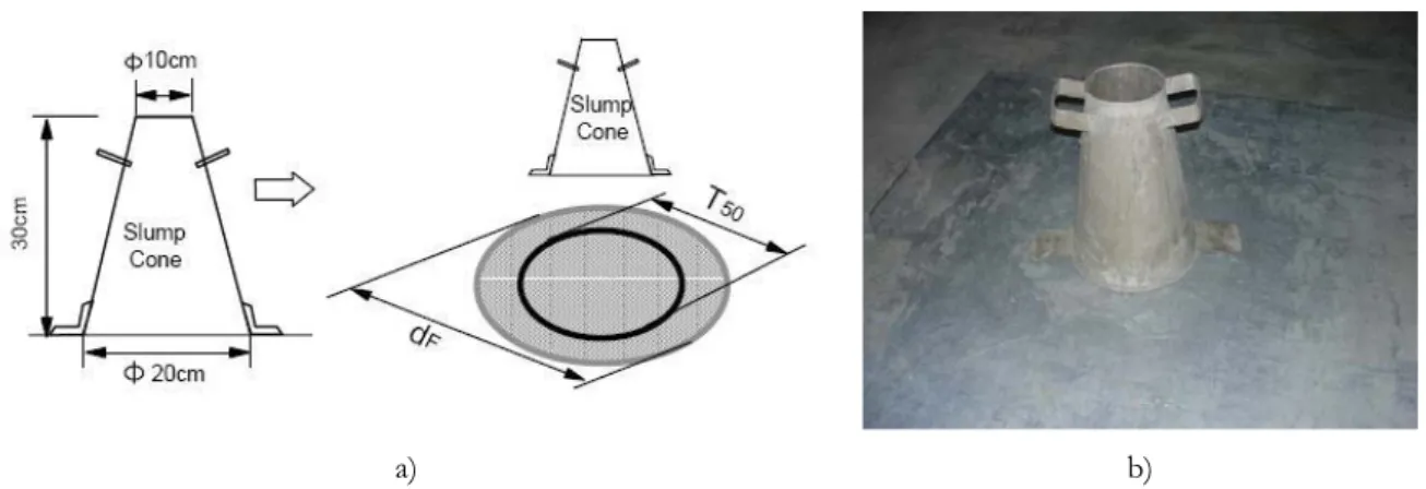
The slump flow test is used to assess the horizontal free flow of SCC in the absence of obstructions as well as its filling ability under its own weight. It was first developed and standardized in Japan (JSCE-F503, 1990) for use in assessment of underwater concrete. The test method is based on the Abrams Cone test, which is the most used to assess the workability and fluidity of fresh concrete. It can also detect, by visualization, the occurrence of segregation and bleeding, which is manifested by the separation of the paste around the perimeter, presence of coarse aggregate without mortar and irregularity in the distribution of coarse aggregate (Bartos, 2000) . The diameter of the concrete circle is a measure for the filling ability of the concrete.
Simão Pedro Fonseca Santos – University of Minho, Portugal 8-119
The characteristics of the instruments are specified in EN 12350-2 (2000) and ISO 1920-2 (2005) standards. The inferior and superior bases of the Abrams Cone have 200 mm and 100 mm diameter, respectively, while its height is 300 mm. In a steel base plate, two concentric circumferences are marked; one with 200 mm of diameter and the other with 500 mm of diameter (see Figure 2.1).
a) b)
Figure 2.1: Flow Test Apparatus: a) representation; b) real apparatus
The diameter of the final spread (df) is measured as the average of two perpendicular diameters, along with the time (T50) taken to reach a diameter of 50cm (d50), as shown in Figure 2.2.
The higher the slump flow (df) value, the greater is its ability to fill formwork under its own weight. A value of at least 650mm is required for SCC. There is no generally accepted advice on what are reasonable tolerances about a specified value, though ± 50mm, depending on the flow table test, might be appropriate. The T50 time is a secondary indication of flow. A lower time indicates greater
flowability. The Brite EuRam (1996) research suggested that a time of 3-7 seconds is acceptable for civil engineering applications, and 2-5 seconds for housing applications.
Simão Pedro Fonseca Santos – University of Minho, Portugal 9-119
In case of severe segregation high percentage of coarse aggregate remains in the centre of the pool of concrete and mortar and cement paste at the concrete periphery. In case of minor segregation a border of mortar without coarse aggregate can occur at the edge of the pool of concrete.
Abrams Cone with J-Ring
Slump Flow test does not provide a direct measure of the passing ability of the concrete. To assess the fluidity of SCC, when it should be passed through steel bars in RC elements, a combination of Abrams Cone and J-Ring is used to study the blockage (Groth and Nemegeer, 1999), placing the Abrams Cone inside the J-Ring (see Figure 2.3). The equipment consists of an open steel ring, drilled vertically with holes to accept threaded sections of reinforcement bar. These bars can have different diameters and can be spaced at different intervals: in accordance with normal reinforcement considerations, 3 times the maximum aggregate size might be appropriate. The diameter of the ring of vertical bars is 300mm, and the height 100 mm.
a) b)
Figure 2.3: Abrams Cone with J-Ring Slump Flow Test Apparatus: a) representation; b) real apparatus
2.2.2. L-Box Test
This test is based on a Japanese design for underwater concrete (Petersson et al (1996), Bartos and Grauers (1999) and Sedran and De Larrard (1999)). The test assesses the flow of the concrete, and also the extent to which it is subject to blocking by reinforcement. The apparatus is shown in Figure 2.4 and consists of a rectangular-section box in the shape of an ‘L’, with a vertical and horizontal
Simão Pedro Fonseca Santos – University of Minho, Portugal 10-119
channel, separated by a moveable gate made of steel bar. The vertical section, with a capacity of approximately 12 dm3, is filled with concrete; than the gate is lifted to let the concrete to flow into
the horizontal channel that has the same dimension of the cross section of the channel.
a) b)
Figure 2.4: L-Box test apparatus: a) representation; b) real apparatus
When the flow has stopped, the heights of the concrete at the end of the vertical (H1) and
horizontal (H2) channels are measured, and the H2/H1 ratio is determined (see Figures 2.4 to 2.7). This ratio represents the passing ability, or the degree to which the passage of concrete through the bars is restricted. The horizontal channel of the box can be marked at 200mm and 400mm from the gate and the times taken to go through these distances are measured and attributed to T20 and T40
variables that give an indication of the concrete filling ability. The steel bars of the gate can be of different diameters and spaced at different intervals: in accordance with normal reinforcement considerations, 3 times the maximum aggregate size might be appropriate. The bars can principally be set at any spacing to impose a more or less severe test of the passing ability of the concrete.
Simão Pedro Fonseca Santos – University of Minho, Portugal 11-119
Figure 2.5: End of test Figure 2.6: Measuring H2 Figure 2.7: Measuring H1 If the concrete flows as freely as water, at rest it will be horizontal, so H2/H1 = 1. Therefore the nearer this test value, the ‘blocking ratio’ (Cbl), is to unity, the better the flow of the
concrete. The EU research team (Brite Euram, 2002) suggested a minimum acceptable value of 0.8. T20 and T40 times can give some indication of how ease concrete flows, but no general consensus
was still found for the values to attribute to these parameters. Blocking of coarse aggregate behind the reinforcing bars of the gate can be detected visually. Occurrence of segregation can also be visualized in qualitative manner.
2.2.3. U-Box Test
The test was developed by the Technology Research Centre of the Taisei Corporation in Japan (Rooney and Bartos, 2001). Sometimes the apparatus is called as “box-shaped” test. The test is used to measure the filling ability of self-compacting concrete. The apparatus consists of a vessel that is divided into two compartments by a middle wall (see Figure 2.10). An opening with a sliding gate is fitted between the two compartments. Steel bars with nominal diameter of 12 mm are installed at the gate with centre-to-centre spacing of 47 mm. This creates a clear spacing of 35 mm between the bars. The left hand channel is filled with about 20 dm3 of concrete then the gate lifted and concrete
flows upwards into the other channel. When flowing is stabilized, the height of the concrete in both sections is measured.
Simão Pedro Fonseca Santos – University of Minho, Portugal 12-119
Figure 2.8: U-Box test apparatus
If the concrete flows as freely as water, at rest it will be horizontal, so H2-H1 = 0.
Therefore the nearer this test value, the ‘filling height’, is to zero, the better the flow and passing ability of the concrete. When the filling height is greater than 300mm, it is considered that the concrete has good filling ability.
2.2.4. V-Funnel Test
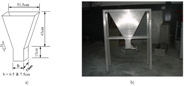
The test was developed in Japan and used by Ozawa et al in the University of Tokyo (Gomes, 2002). The equipment consists of a V-shaped funnel, shown in Figure 2.9. An alternative type of V-funnel, the O-funnel, with a circular section is also used in Japan. The described V-funnel test is used to determine the filling ability (flowability) of the concrete with a maximum aggregate size of 20mm.
The funnel is filled with about 12 dm3 of concrete and the time taken to flow through the
apparatus is measured for first time. After this, the funnel can be refilled with concrete and left for 5 minutes to settle, in order to make another measure of the flowing time. If the concrete shows segregation then the value of the second flow time will increase significantly.
Simão Pedro Fonseca Santos – University of Minho, Portugal 13-119
a) b)
Figure 2.9: V-Funnel test apparatus: a) representation; b) real apparatus
This test measures how easily concrete can flow; shorter flow times indicate greater flowability. For SCC a flow time of 10 seconds is considered appropriate (Ozawa et al., 1994). The inverted cone shape restricts flow, and prolonged flow times may give some indication of the susceptibility of the mix to block.
2.2.5. Orimet Test
The Orimet test was developed by Bartos in 1978 (Bartos, 1992). It is not as used as the previous ones. The test consists in the determination of the time that 10 dm3 of concrete takes to flow out of
a vertical cylindrical tube of diameter 8 cm, with a funnel at the end (see Figure 2.10). The test has been applied to concretes of high workability and, recently, for SCC (Gomes, 2002). For SCC, two steel perpendicular bars of 10 mm diameter were inserted in the funnel to evaluate the passing ability. Once more, the flow time measures the filling ability of concrete; for SCC, the recommended flow times are < 3 s (Bartos and Grauers (1999) and Sonebi and Bartos (2000)).
Simão Pedro Fonseca Santos – University of Minho, Portugal 14-119
Figure 2.10: Orimet Test Apparatus with J-Ring
2.3. The possibilities of steel-fibre reinforced concrete: an overview
Mostly of the authors consider unanimously Self Compacting Concrete as a great and a promising material within the construction industry. SCC is treated like an extraordinary material, with extraordinary characteristics that allows the development of structures with high complex geometry, almost impossible to be made with traditional concretes. The same happens with High Strength Concretes, High Performance Concretes as well as with Steel Fibre Reinforced Concretes, where, due to of all the I&D already done, is possible to asseverate the behaviour in many real conditions.
The consolidation of SCC as a construction material in conventional applications increases every day (Mas, 2005). In Europe, countries like France, Italy and Holand have already great percentages of applications of this material. Portugal and Spain, where traditionally, this sector is very different from the others, SCC is starting to give its first steps, although the lack of normative related. In Spain, the first Spanish Congress on Self-Compacting Concrete happened in 2007 (HAC 2008), which shows that, although this theme is giving the first steps in this country, this technology is getting more and more attention from enterprises and academic community.
The present wok will board, especially, the application of SFRSCC in the precasting industry. The concrete precasting industry is where SCC technology is growing up faster, since the evaluation of cost production is much simpler and where all the economical advantages of this material can be better appreciated. There are also all the advantages from the quality environment point of view, with the elimination of constant noises of vibrators and the reduction of labour risks in long term.
Simão Pedro Fonseca Santos – University of Minho, Portugal 15-119
In addition, the final quality of the products can be much better, which is a relevant characteristic in several precasting elements.
The following table shows the evaluation of times of execution and implication of worker in a common unity of prefabrication.
Table 2.1: Times of execution and implication of worker
3,5 m3 Slab 5,5 m3 Doble Slab in T
Conventional
Concrete Self-Compacting Concrete Conventional Concrete Self-Compacting Concrete Implicated Worker 6 workers 3 workers 7 workers 3 workers
Time of Execution 3 hours 1 hour 3.5 hours 1 hour
As can be seen in Table 2.1, the additional costs associated to the production of SCC can be easily amortized by the savings in implicated worker and time of execution. Besides, the increasing life cycle of moulds turns the technology of SFRSCC in a cheaper way to produce precasted elements.
But the advantages are not only visible in the precasting industry. Mas (2005) shows the great advantages of the utilization of SCC in conventional edifications like filling slabs, pavements, support walls and other elements.
To a detailed description of SFRSCC’s and SCC’s possibilities, see (Pereira, 2005) and (Domone, 2006).
2.4. Conclusions
The main properties and the principal test procedures of SCC have been reviewed. The study shows that the characterization of the behaviour of SFRSCC in fresh state needs new test methods since the traditional tests are not applicable. From all these tests, only the Slump Flow test, Slump Flow with J-Ring test and L-Box test were used in the experimental programs carried out within the ambit of the present dissertation. The other tests were not used, since their applicability is too questionable
Simão Pedro Fonseca Santos – University of Minho, Portugal 16-119
due to the fact that the dosages of steel fibres on the manufactured elements were relatively high. No specific tests are available for SFRSCC: so, in this work, an adaptation of the tests to SCC was made, in order to characterize the concrete compositions in fresh state. New methods must be developed with this purpose.
Simão Pedro Fonseca Santos – University of Minho, Portugal 17-119
3.
F
AÇADE
P
ANELS IN
S
TEEL
F
IBRE
S
ELF-
C
OMPACTING
C
ONCRETE
3.1. Introduction
The Precast Industry is the Civil Construction related industry where the usage of SCC can conduce to greater advantages, since the reduction of time and efforts to provide manual finishing to the cast elements - derived from the improvement of quality of surfaces - the increase of the life cycle of moulds or the usage of lighter moulds. For these reasons, since its introduction, the concept of SCC caught the attentions of researchers and professionals of construction industry, thanks to its advantages and attractive properties in fresh and hardened state.
The quality of produced elements depends directly of the technology within the factory; many efforts are taken to develop new technology in materials, equipment and production processes in order to improve the quality and competitiveness of concrete elements. Besides, there are all the obligations related with the environment consciousness, which imposes more and more restrictive conditions to the design and construction practices, turning very tight the obtaining of construction approvals under the inspection of competent entities.
SCC technology can be very useful in this kind of industry. The perfection of the elements is reached with no necessity of extra-qualified worker; this perfection does not depend on the vibration (principal responsible for the refusal of the pieces by the Quality Control Departments); with no vibration directly applied to the moulds, they have a bigger useful life; and, as it was already mentioned in Chapter 2, the absence of vibration creates a better environment within the industrial naves, without noise and much cleaner.
Simão Pedro Fonseca Santos – University of Minho, Portugal 18-119
For the other hand, in concrete precast industry, the complexity of forms and geometries obligates many times the adoption of great percentages of reinforcement which, no rarely, turn the filling process a very difficult task. These problems are being investigated since longer. The partial or total replacement of the concrete reinforcement by discrete steel fibres is being pursued from long years ago (ACI, 1996), since there are several examples of concrete elements only requiring reinforcement to control cracking phenomena.
In this type of elements SFRSCC is an effective alternative since the benefits of SCC and fibre reinforcement can be combined to obtain a material of great ductility high energy absorption capacity.
To evaluate how effective can be this alternative, an experimental program was carried out to characterize an SFRSCC to be used in façade panels for buildings. Several requirements were defined so the production of this kind of elements can be presented as an alternative.
.
In the precast concrete industry, besides the perfect finishing, the ability to demould the elements as soon as possible is an extremely important requirement. To assure a safe demoulding process, the influence of the concrete age on the flexural and compression behaviour of the SFRSCC must be known. During the process of demoulding and stocking, the elements are submitted to relatively high stress levels that can produce damages in an irreversible way. This conducts to the refuse of these elements by the Quality Control process, with the inherent costs that it imposes. So, one of the establishments for a secure demoulding process is to guarantee that a minimum level of resistance have already been achieved before the start of this process. This level of resistance is evaluated by the concrete compressive strength. In the present case, a minimum compressive strength of 20 MPa, 24 hours after the casting operations, must be reached.
In order to start the demoulding process as soon as possible, the precast industry tries to accelerate the cure of the concrete elements. One of the most common processes to accelerate the process of cure of concrete is to provide external fonts of heat directly applied to the moulds and the elements, especially in the winter, when the air temperatures are lower. This practice results very expensive, due to the enormous energy consumption, which, obviously, increases the final price of the manufactured products. As the SCC compositions have less water dosage than a current concrete, its cure process is, in general, faster than for a normal water dosage concrete.
Simão Pedro Fonseca Santos – University of Minho, Portugal 19-119
The panels can’t be too heavy, since its weight can generate difficult application in the building’s façades. In the present experimental program, a laminar (4100×2200×110) mm2 (current
dimensions in these kind of elements) façade panel should be built; considering a massive panel it would have a weight of approximately 24.81 kN, which would be too much for a façade panel. In order to decrease the weight of the panels, (300×300×80) mm3 polystyrene plates were used in order
to create a mesh with massive (100×110) mm2 perpendicular lines and zones that with a SFRSCC
layer with a thickness of 30mm (see Figures 3.41 to 3.47). This will permit the construction of a panel with an approximate weight of 13.05 kN.
So, when installed in building façades, the panel’s flexural strength is the principal design property, since significant bending moments result from wind loading, which has the greatest impact on the most unfavorable load combination. Representative elements of the SFRSCC panel system were tested to assess its flexural behaviour. Since the SFRSCC layer at the lightweight parts of the panel is only 30 mm thick, its resistance to punching was also determined, based on experimental research.
The research program ended with the fabrication of a real size panel in industrial environment. This panel was loaded up to failure in order to evaluate its load carrying capacity.
3.2. Material constituents
The used materials were cement (C) CEM I 42.5R, limestone filler (LF), superplasticizer (SP) of third generation based on polycarboxilates (Glenium® 77 SCC), water (W), three types of aggregates (fine river sand, coarse river sand and crushed granite 5-12 mm) and DRAMIX® RC-80/60-BN hooked end steel fibres. This fibre has a length (lf) of 60 mm, a diameter (df) of 0.75 mm, an aspect
Simão Pedro Fonseca Santos – University of Minho, Portugal 20-119
3.3. Mix design method for self-compacting concrete admixtures
The method used in the present work is based on the three following steps (Pereira, 2006): i) definition of proportions of the constituent materials of the binder paste; ii) determination of proportions of each aggregate on the final solid skeleton; iii) mix binder paste and solid skeleton in different proportions until self-compacting requirements in terms of spread ability, correct flow velocity, filling ability, blockage and segregation resistance are assured. Each one of these steps is exposed in the following paragraphs.
In the first step, a series of tests were performed to achieve the optimum composition of the binder paste. To define the optimum percentage of Limestone Filler (LF) addition in the final composition, several mixes of LF, cement and water were prepared. The proportions of each component were defined in terms of volume; the water content was 66% of cement volume, and the percentage of LF has varied between 0% and 125% of the cement volume. To promote the dispersion and deflocculation of the fine particles in suspension, a small constant quantity of superplasticizer was also added to each mix. The relative spread in the Flow table and the Marsh cone flow time of each mix were measured. Concluding the paste phase design, the compression strength of each mix was also evaluated on 5 cm edge cubic specimens at an age of 7 days. A percentage of 100% of LF relative to the cement volume has resulted in a good compromise between strength and flowability requirements, and has also allowed maintaining the amount of cement on the final concrete mix only slightly above 350 kg/m3.
In the second step, the most appropriate proportions of the three types of aggregates were obtained preparing mixes of distinct quantities of each type of aggregate, and weighting 5 dm3 for
each mix. The optimum aggregate mix was assumed to be the heaviest one, since it should correspond to the most compact mixture. An estimated portion of fibres equivalent to 30 kg of fibres per m3 of concrete was included in each mixture. Initially, only two of the three types of
aggregates were mixed; after finding the optimum relation between these two, the third aggregate was added in distinct volumetric percentages, keeping constant the relation between the two first aggregates. These results indicated that the optimum solid skeleton was composed - in volume - by 49.5% of coarse sand, 40.5% of crushed stone and 10% of fine sand.
Simão Pedro Fonseca Santos – University of Minho, Portugal 21-119
The third phase was dedicated to the evaluation of the paste content in the concrete volume. The optimum composition should accomplish an upper limit of around 350 kg of cement per m3 of
concrete. To achieve the optimum paste content, some mixes of concrete were prepared, varying the paste percentage. For each mix, the added water was evaluated taking into account the aggregate’s saturation degree. The mix process was always the same, and for each mix the slump flow test was performed. Total spread, df, and time to reach a spread diameter of 50 cm, T50, were measured. Table
3.1 includes the composition that has best fitted self-compacting requirements (the amount of water referred includes the aggregate’s saturation water). No sign of segregation was detected, a total spread of 725 mm was measured and the mixture showed good homogeneity and cohesion, even when flowing trough the small orifice of the Abrams cone (when testing, Abrams cone was always used in the inverted position). A T50 of 4.6 seconds was measured.
Table 3.1:FinalComposition for 1 m3 of SFRSCC 30 kg of fibres
3.4. Material Properties
3.4.1. Compression
The experimental program was composed by uniaxial compression tests with cylinders of 150 mm diameter and 300 mm height, and flexural tests with prismatic (600×150×150) mm3 specimens. Both
types of specimens were molded without any external compaction. To assess the influence of the age of SFRSCC on the compression and on the flexural behaviour, series of tests with specimens of 12 and 24 hours, and 3, 7 and 28 days were carried out.
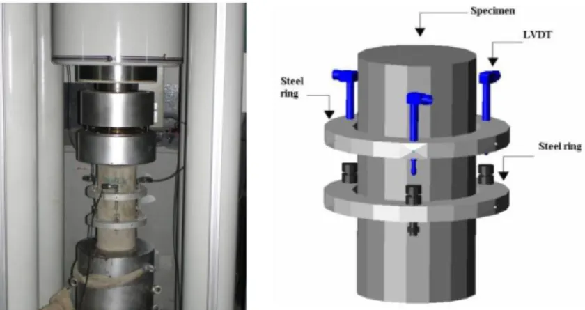
The Young Modulus (Ec) is determined according to the recommendations of the LNEC E397-1993 standard, using the test setup represented in Figure 3.1. This test setup is
composed by two rings at 100mm from each other. In the superior ring three Linear Variation Displacement Transducers (LVDT) are placed, making an angle of 120º between them. These LVDT’s read the deformation of the concrete specimen between the two parallel rings. This proceeding avoids the LVDT’s to register extraneous deformations due to equipment.
Composition volume (%) Paste/ Total Cement (kg) (kg) LF Water (dm3) (dmSP 3) Fine sand (kg) Coarse sand (kg) Crushed stone (kg)
Simão Pedro Fonseca Santos – University of Minho, Portugal 22-119
Figure 3.1: Test setup to evaluate the concrete Young’s Modulus, Ec
To start the test, a stress of 0.5 to 1.0 MPa (σb) is applied and the corresponding strain is
measured (εb). The stress is than increased at a velocity of 0.5 ± 0.1 MPa/s until a stress level σa = fc
/ 3 is reached, where fc is the compressive strength, previously obtained in direct compression tests
with concrete cylinder specimens. The stress σa is maintained during 90 seconds, and in the last 30
seconds of this period, the strains are recorded (εa1). After this period, the load is decreased at a
stress ratio of 0.5 ± 0.1 MPa/s until a stress level σb. This stress level is maintained during a period
of 90 seconds, and in the last 30 seconds of this period, the strains are recorded. The loading configuration of this test is composed of 10 cycles of this type (see Figure 3.2).
Figure 3.2: Representation of load cycles to determine Ec
The Young’s Modulus, Ec, is the average of the Ec,n values obtained in each cycle (see Equation 3.1):
, , , , , a n b n n c n n a n b n E σ σ σ ε ε ε − Δ = = Δ − (3.1)
Simão Pedro Fonseca Santos – University of Minho, Portugal 23-119
Compression tests were carried out in a servo-controlled equipment of 3000 kN maximum load carrying capacity. Each test was controlled by the internal displacement transducer of this equipment, at a displacement rate of 5 µm/s. Three displacement transducers were positioned at 120 degrees around the specimen to record the displacements between the load steel plates of the equipment (see Figure 3.3). Once more, this arrangement of the LVDTs avoids that extraneous deformation - such as the deformation of the reaction frame - can be added to the values recorded by the LVDTs.
Taking the values recorded in these transducers, the displacement at the specimen axis was determined for each scan reading, and the corresponding strain was obtained dividing this displacement by the measured specimen’s height
Figure 3.3: Configuration of compression test and position of the LVDT’s
3.4.1.1.1 Results
The compression stress-strain relationship,σc−εc, for each testing age of SFRSCC is represented in
Figure 3.4. Each curve is the average of three specimens. As it was expected, the decay of the post-peak residual compression strength has increased with the SFRSCC age, since the material becomes more brittle with the increase of the compressive strength. However, this decay is not as pronounced as it will be expected for plain concrete.
Simão Pedro Fonseca Santos – University of Minho, Portugal 24-119
Figure 3.5 checks if the σc−εc expressions proposed by Model Code CEB-FIP 1993 to
simulate the uniaxial compression behaviour of plain concrete can be applicable to the developed
SFRSCC. This figure shows that those expressions simulate with high accuracy the uniaxial
compression behaviour of the designed SFRSCC up to its peak stress, but in the softening phase (post-peak) they predict stress decay higher than the one observed experimentally.
0 10 20 30 40 50 60 70 0 2.5 5 7.5 10 12.5 15 17.5 Strain (‰) Str ess ( M Pa) 12 hours 24 hours 28 days 3 days 7 days
Figure 3.4: Stress-strain curves of SFRCSCC of different ages.
12 hours 24 hours 3 days 7 days 28 days 0 10 20 30 40 50 60 70 0 2 4 6 8 10 Strain (‰) Stre ss (MPa) experimental CEB-FIP 1993
Figure 3.5: Evaluation of the applicability of CEB-FIP 1993 expressions to simulate the behaviour of SFRSCC
Simão Pedro Fonseca Santos – University of Minho, Portugal 25-119
Figures 3.6 and 3.7 show the influence of the age on the average compressive strength, fcm,
and on the average initial Young’s Modulus, Ecm. From the analysis of these figures, the following
observations can be pointed out: at 12 hours the pre-established minimum limit of 20 MPa for the compressive strength at 24 hours had already been exceeded; at this age the fcm was about 25 MPa
while the Ecm was around 24 GPa. These properties increased with the SFRSCC age, reaching fcm = 62 MPa and Ecm = 36 GPa at 28 days. The evolution of the compressive strength with time
indicates that, above 28 days the increase of fcm is marginal. This can be justified by the use of
relatively high percentage of a material (LF) without pozolanic activity in the binder paste composition. The evolution of the Young’s Modulus with the age indicates that above 28 days the increase of the Ecm is marginal. This can be justified by the low value of the water/cement (w/c)
ratio (approximately 0.28 in weight), since a high compact matrix has resulted. At 24 hours the fcm
and the Ecm were about 61% and 79% of the corresponding values at 28 days. In the first hours,
there was a more pronounced increase in Ecm than in fcm.
0 10 20 30 40 50 60 70 0 5 10 15 20 25 30 Age (days) fcm (MP a)
Figure 3.6: Variation of fcm with age.
20 22 24 26 28 30 32 34 36 38 40 0 5 10 15 20 25 30 Age (days) Ec m (G Pa )
Simão Pedro Fonseca Santos – University of Minho, Portugal 26-119
3.4.2. Bending
In the bending tests, the curing procedures, the position and dimensions of the notch sawn into the specimen, the load and specimen support conditions, the characteristics for both the equipment and measuring devices and the test procedures recommended by RILEM TC 162-TDF (Vandewalle, 2002) were adopted. The method for casting the beam specimens proposed by RILEM TC 162-TDF was adapted for the case of SFRSCC since these specimens were cast without any external compaction energy.
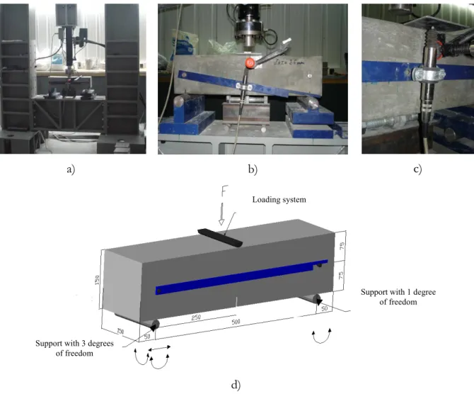
RILEM TC 162-TDF recommends the use of (600×150×150) mm3 beams, with a notch of
2-3 mm thick and 25±1 mm depth at the specimen middle surface. The test setup is represented in Figure 3.8. At the notch mouth a “clip gauge” can be applied to measure the crack opening.
The LVDT is attached to a bar that is supported in two fixed points of the specimen. The bar may rotate in turn of one of these points and slide along the other one (Figure 3.8d). This arrangement for the support of the LVDT is designated by “Yoke system” (Gopalaratnam et al. 1991) and avoids extraneous deflections to be read by the LVDT. The reaction frame must have enough stiffness to avoid the occurrence of unstable tests (Van Mier, 1984).
Simão Pedro Fonseca Santos – University of Minho, Portugal 27-119
a) b) c)
d)
Figure 3.8: Bending Test Setup
The quality of the controller equipment and the stiffness of the reaction structure used in this project, allow performing stable tests under displacement control. The load cell, with maximum load capacity of 50 kN, has a linearity class of 0.03% of full scale. The LVDT presents a linearity class of 0.1% of full scale (5 mm) and a repeatability of 0.01% of full scale.
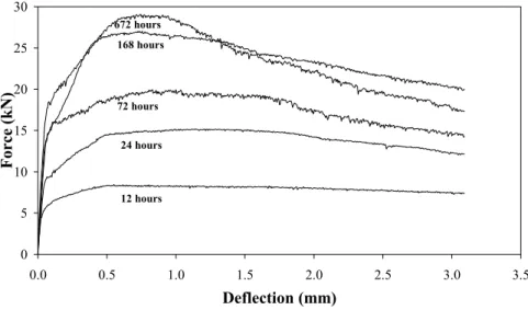
The crack must start in the notch; otherwise the test must be rejected. The test is carried out at a deflection ratio of 0.2 mm/min. The test ends when a displacement of 3.1 mm is reached.
Figure 3.9 represents a typical force-deflection (F-δ) relationship obtained in a bending test. Using these relationships, RILEM TC 162-TDF proposed the evaluation of the load at the limit of proportionality (FL), the equivalent (feq,2 and feq,3) and the residual (fR,1 and fR,4) flexural tensile strength
Support with 1 degree of freedom
Support with 3 degrees of freedom
Simão Pedro Fonseca Santos – University of Minho, Portugal 28-119
parameters (Vandewalle et al. 2000, 2002). FL is the highest value of the load recorded up to a
deflection of 0.05 mm. 0.05 F [kN] L F [mm] (a) 0.35 F [N] L F δ [mm] 0.3 L δ BZ b D δ2 FR,1 R,1 δ BZ,2 f D (b) F [N] 2.35 L 0.3 δ δ [mm] δ3 R,4 F δR,4 FL DbBZ f BZ,3 D (c)
Figure 3.9: Normal Load-Displacement relation in a bending test
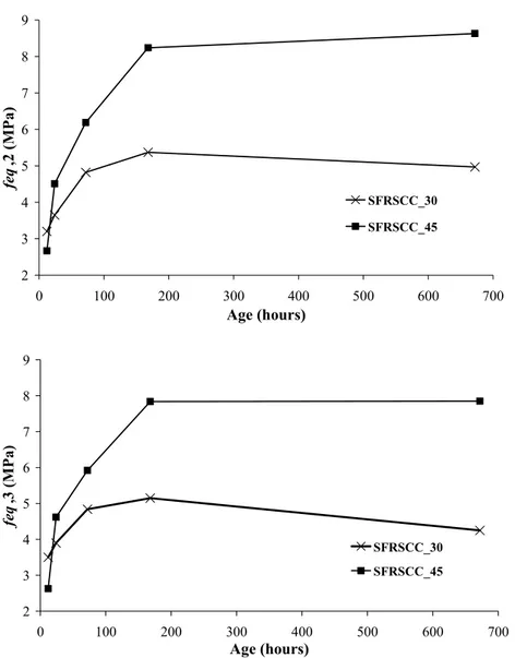
The parameters feq,2 and feq,3 are related to the material energy absorption capacity up to a deflection of δ2 and δ3 (δ2 = δL + 0.65mm and δ3 = δL + 2.65mm, where δL is the deflection
corresponding to FL) provided by fibre reinforcement mechanisms ( ,2 f BZ
D and DBZf ,3), as seen in
Figure 3.9. The parcel of the energy due to matrix cracking ( b BZ
D ) is not considered in the feq
evaluation. The parameters fR,1 and fR,4 are the stresses for the forces FR,1 and FR,4, respectively, at
deflection of δR,1 = 0.46 mm and δR,4 = 3.0 mm. Assuming a linear stress distribution in the cross
section (see Figure 3.10), the equivalent (Vandewalle et al. 2000) and the residual (Vandewalle et al. 2002) flexural tensile strength parameters are obtained from the following expressions:
,2 ,3 ,2 2 ,3 2 3 ; 3 2 0.50 2 2.50 f f BZ BZ eq eq sp sp D L D L f f bh bh = = [N/mm2] (3.2) ,1 ,4 ,1 2 ,4 2 3 3 ; 2 2 R R R R sp sp F L F L f f bh bh = = [N/mm2] (3.3)