The structural behavior and the ultimate punching shear resistance of internal reinforced concrete lat slab-column connections, with one hole adjacent to the column, with or without lexural moment transfer of the slab to the column was investigated. Main variables were: the existence whether or not hole, lexural reinforcement layout and ratio, the direction and sense of the moment transferred and the eccentricity of the load (M (moment transferred to column) / V (shear)) ratio at the connection - 0,50 m or 0,25 m. Seven internal slab-column joining were tested and ultimate loads, cracking, delec
-tions, concrete and reinforcement strains were analyzed. The existence of hole adjacent to the smaller column dimension, the hole dimension, lexural reinforcement rate and placing, the variation of relation Mu/Vu in function of the load, and, than, of eccentricity of the load, inluenced the slabs behavior and rupture load. Test results were compared with the estimations from CEB-FIP/MC1990 [7], EC2/2004 [12], ACI-318:2011 [1] and NBR 6118:2007 [5]. ACI [1] and EC2 [12] presented most conservative estimates, although have presented some non conservative estimates. Brazilian NBR [5], even though being partly based in EC2 [12], presented smaller conservative estimates and more non conservative estimates. A modiication on all codes is proposed for taking in account the moment caused by the eccentricity at the critical perimeter for slabs with holes.
Keywords: structures, lat slabs, reinforced concrete, punching shear, hole.
São investigados o comportamento estrutural e a resistência última à punção de ligações laje-pilar de regiões internas das lajes lisas, com um furo adjacente ao pilar, e com ou sem transferência de momento letor da laje ao pilar. As principais variáveis foram: a existência ou não de furo, a taxa e a distribuição da armadura de lexão, a direção e o sentido do momento transferido e a excentricidade de carga (relação M(momento transferido ao pilar)/V(força cortante)) na ligação, igual a 0,50 m ou 0,25 m. Foram ensaiadas 7 (sete) ligações internas laje-pilar e analisados os resultados das cargas últimas, issuração, deslocamento vertical, deformações das armaduras de lexão e do concreto. A existência de furo adjacente ao menor lado do pilar, a taxa e a distribuição da armadura de lexão, a variação da relação Mu/Vu em função do carregamento, e, por conseguinte, da excentricidade, inluenciaram o comportamento e a carga de ruptura das lajes. Os resultados expe
-rimentais foram comparados com os estimados pelas normas: CEB-FIP/MC1990 [7], EC2/2004 [12], ACI-318:2011 [1] e NBR 6118:2007 [5]. O ACI [1] e o EC2 [12] apresentaram estimativas mais conservadoras, embora tenham apresentado algumas estimativas contra a segurança. A NBR 6118:2007 [5], apesar de baseada em parte no EC2 [12], apresentou estimativas menos conservadoras e com um número maior de
estimativas contra a segurança.
Palavras-chave: estruturas, laje lisa, concreto armado, punção, furo.
Punching shear in reinforced concrete lat slabs with
hole adjacent to the column and moment transfer
Punção em lajes lisas de concreto armado com furo
adjacente ao pilar e transferência de momento
D. C. OLIVEIRA a [email protected]
R. B. GOMES a [email protected]
G. S. MELO b [email protected]
a School of Civil Engineering, Federal University of Goias, Goiânia, Brazil;
b Department of Civil and Environmental Engineering, University of Brasilia, Brasilia, Brazil.
Abstract
1. Introduction
Flat slabs according to NBR 6118:2007 [4] are lat horizontal laminar structures, directly supported on columns. It is an alterna
-tive structural system to the conventional one, in which slabs are supported on beams. The absence of beams may present some advantages, such as saving formwork, reduced height, increased number of stories for buildings with quota limitation and greater lexibility for architectural arrangement. The adoption of lat slabs
also enables greater slab panels speed execution, which makes them more economical, comparing to conventional system with beams. This increased speed can be obtained by constructive sim
-plicity, facilitating implementation means, reducing the cutting due
to the beams absence; in the cut, fold and placement of reinforce-ments, and concreting.
A disadvantage of lat slabs is the possibility of a punching fail
-ure for a lower load that would be the fract-ure load by bending. The rupture by punching occurs suddenly, with little or no warning,
Figure 1 – Testing system, top view and section (mm)
400
600 SECTION AA
Block Slab
2400 500 120
200 Distribution plate
(120x200mm)
Hydraulic actuators
(load application) Distribution beam
200 TOP VIEW
Slab reaction
A
200
B B
A SECTION BB
600
150
400 300
500 Column
Hydraulic actuator (pre-stressing)
1200
150
Load cell
Hydraulic
actuator 212.5 Tie
300 212.5
Block 2400
1000
1000
1000
1000 200 200 200
200
N
S
W E
Column
Central tie (pre-stressing)
Metal box Metal plate
Metal plate
Slab reaction
Load cell Load cell
Metal box Metal plate
Hydraulic actuator
(pre-stressing) Central tie(pre-stressing)
Slab
almost without ductility, which may lead to a progressive collapse (propagation of a failure that was originally held in a small part of the structure, in which the resulting damage is disproportionately
larger than the original).
1.1 Justiication
Despite this structural system (lat slabs) being widely used, the shear punching study is not yet theoretically a fully deined subject. International codes and national standards address this subject
(shear punching), based on empirical studies. The criteria used for
sizing are not the same and speciic calculations given are often asked by scholars in the area. Experimental researches are crucial for understanding the many issues surrounding the use of this type of system.
Several experimental studies have been conducted abroad and in Brazil, evaluating the shear punching resistance of reinforced concrete flat slabs and addressing many aspects, such as concentrated loads, existence of shear reinforcement, border columns, existence of openings and moment transfer, quoting HANDON and HANSON [16], REGAN [20], TAKEYA [25], CARVALHO [8], GOMES and REGAN [13 and 14], PINTO [19], CORDOVIL [10], GOMES and ANDRADE [15], SANTOS [22], DIAS [11], VARGAS [27] , OLIVEIRA [17], ANDRADE [3], COELHO [9], REGAN [21], ANDRADE [2], TRAUTWEIN [26], OLIVEIRA [18], BORGES [6], SOUZA [23] and SOUZA [24]. Among these studies, we highlight the “Shear punching in Re
-inforced Concrete Flat Plates with Openings Adjacent to Col
-umn and Moment Transfer”, SOUZA [24], in which this study was based on. This research contributes to the solution of the problem of flat slabs shear punching with openings, and flex -ural moment transfer of the slab to the column.
1.2 Literature 2eview
1.2.1 Regan [20]
REGAN [20] evaluated the effect of openings positioned adjacently to columns in the shear punching resistance of lat slabs, and tried to minimize the loss of this resistance by using shear reinforce
-ment. Eight square slabs of 2000 mm length and 160 mm thick
-ness were tested. They were supported in the center of a column of 250 mm x 150 mm. A load was applied in eight loading points, two at each end of the slab. From this research the author con -cluded that the shear reinforcement placed beside the openings
can be highly effective to restore lost strength due to the opening.
1.2.2 Gomes e Andrade [15]
At Furnas Centrais Elétricas SA in Aparecida de Goiânia,Goiás, GOMES and ANDRADE [15] researched the inluence of shear re
-inforcement “stud” type on shear punching resistance of lat slabs with openings near the column region, which simulated the pas -sage of pipes through slabs. According to the authors, the results
showed that the openings reduced the shear punching resistance of a smooth reinforced concrete slab. However, the use of shear reinforcement with openings allowed to recover the loss, even in regions where the concrete was minimal.
1.2.3 Souza [24]
SOUZA [24] jointly investigated the effect of the use of adjacent openings and the application of bending moment. 19 squared lat slabs of 2400 mm length and thickness of 150 mm were tested. They were monolithically connected to a column with 850 mm
Table 1 – Characteristics and failure loads of BORGES' slabs [6]
Slab
(a) Slab without opening - without anchoring hook. (b) Slab without shear reinforcement.
c , c – the column dimensions (mm); d – slab effective height (mm); f – Cylinder compressive strength of concrete (MPa); 1 2 c
ρ - slab reinforcement ratio (%); holes - indicates the number of holes; Hook anchoring – indicates anchorage hook presence or absence; V – slab failure load.u
F – one opening; FF – two openings; S – no extra bar, D – with addition of bar; CG – with anchorage hook; ACi – shear reinforcement type “I”.
L45 L45FS_CG L45FD L45FD_CG L45FFS_CG L45FFD L45FFD_CG L45FFD_AC 2 L45FFD_AC 3 L45FFD_AC 4 L45FFD_AC 5
c1 c2 200 200 200 200 200 200 200 200 200 200 200 600 600 600 600 600 600 600 600 600 600 600 154 154 154 154 154 144 164 154 154 154 154 798 742 726 700 700 635 800 1180 1000 835 787 40.5 40.5 41.4 39.0 41.6 37.0 40.6 43.8 39.6 43.2 40.7 No Yes No Yes Yes No Yes No No No No 0 1 1 1 2 2 2 2 2 2 2
Layers f (mm) (b) (b) (b) (b) (b) (b) (b) 4 3 3 2 (b) (b) (b) (b) (b) (b) (b) 10.0 8.0 8.0 8.0 1.28 1.14 1.38 1.38 1.00 1.38 1.24 1.38 1.38 1.38 1.38
Column (mm) d Shear reinforcement
(mm)
Vu (kN) fc
(300 mm up to 400 mm down) tall with a rectangular cross section 200 mm x 500 mm. The slabs were loaded at the edges, from the top down. Between the slabs, the main features that differ from each other are: quantity, placement and dimensions of the open
-ings, the rate and distribution of lexural reinforcement, the shear reinforcement and the load eccentricity (ratio M (moment trans -ferred to the column) / V (shear)) in slab-column connection. The
test system used is shown in Figure 1. The author concluded that
resistance losses were greater for the slabs with an adjacent open
-ing to the smallest column side, and the adjacent open-ing dimen
-sion greater than the dimen-sion of the column (slabs L2, L3 and L4), which had as variables the rate and the lexural reinforcement position. It is also observed that for slabs with applied moment, the worst situations regarding the loss of resistance with adjacent column opening and moment transfer occurred when the moment is towards the opening region, which is more brittle and has no
concrete to resist compressions in the plate bottom layer, which
are increased due to the moment.
1.2.4 Borges [6]
BORGES [6] analyzed experimentally twenty lat square slabs of reinforced concrete, with 3000 mm length and 200 mm of thick
-ness, aiming to investigate the behavior of slabs with rectangular columns, with some relations between the sides of the column,
openings and reinforced shear. The characteristics and failure
loads of slabs tested are shown in Table 1. In Figure 2 the mod
-els of the tested slabs by BORGES [6] are presented. The au -thor concluded that the shear reinforcement used, consisting of
“studs”, positioned to engage slabs lexural reinforcement, showed adequate performance, leading to a failure surface formation to the outer region with shear steel, and that the resistance of slabs with openings and shear reinforcement can reach and even exceed the strength of similar slabs without openings. The shear reinforce
-ment use in slabs with openings allowed an up to 86 % increase compared to the similar slab with openings and without such steel, and allowed the slab to reach shear punching resistance at least equal to the similar slab without opening. It was also reported that the use of additional lexural reinforcement bars in the region
around the openings caused no increase to slabs shear punching resistance, although it has led to vertical displacements similar to
the reference slab without openings. And the hooks used as an
-chorage of the main lexural reinforcement, which was intercepted by the openings, did not alter the failure loads of the slabs with
openings.
1.2.5 Souza [23]
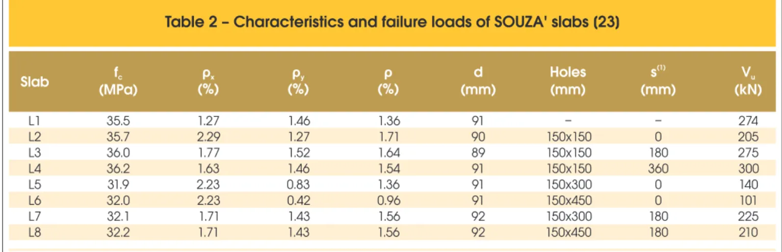
SOUZA [23] investigated the effect of the use of adjacent or dis
-tant column openings in eight lat reinforced concrete lat slabs of 1800 mm x 1800 mm x 130 mm. The characteristics and the slabs failure loads are shown in Table 2. Two openings were made in each slab with varying dimensions, and were located with respect to the square column with 150 mm length, as shown in Figure 3.
Shear reinforcement was not used in any slabs. The failure loads were inversely proportional to the openings dimensions and their
distances related to the column. The author found that openings
in lat slabs of any size located near column signiicantly reduce shear punching resistance. We also found that the studied open -ings at a distance of 4 times effective depth (4d) related to column
surface do not inluence the load and failure mode for shear punch
-ing. Finally, it is shown that more studies should be conducted to a clearer conclusion about the inluence of distant openings in the
column shear punching resistance.
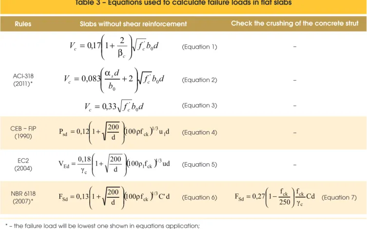
1.2.6 Rules and speciications
The recommendations for calculation of lat slabs are presented in table 3, with and without openings, of the American Concrete Code (ACI/318-2011 [1]), of the European Code (EC2/2004 [12]) and of the Euro-International du Béton Committee (CEB-FIP, 1990 [7]) and the Brazilian Rules (NBR 6118:2007 [5].
Table 4 presents the control perimeters and their locations for lat slabs with openings, where a cut is made in the perimeter control length for slabs without openings, from radial lines, from the center of the column towards the openings. For the calculation of stresses was considered the area corresponding to the perimeter control multiplied by the effective depth of the slab (d). Only CEB-FIP/ MC 1990 [7] does not state in their perimeter control prescriptions, when there are openings, to be considered.
2. Materials and experimental program
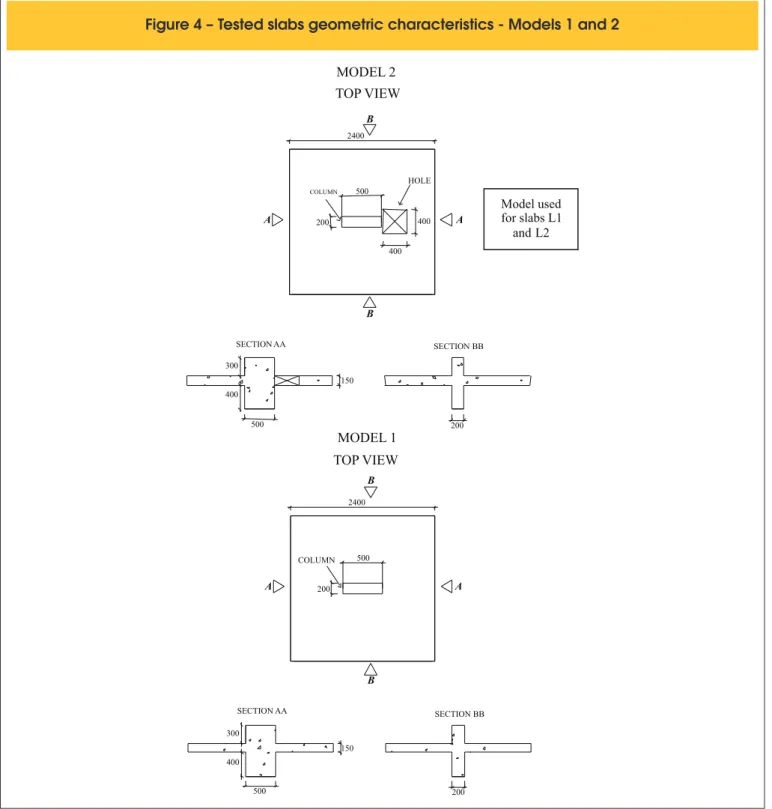
The experimental program was consisted of testing, until seven slabs were ruptured (L1 to L7) aiming to experimentally investi -gate the behavior of slab-column connections in inner regions oflat slabs with one or two adjacent column openings, and with or without lexural moment transfer of the slab to the column. Two geometric patterns were performed. They were told apart by open
-ings, with dimensions according to Figure 4. The main variables involved in this experimental research were: 1) the presence of openings; 2) the rate and distribution of lexural reinforcement; and
Table 2 – Characteristics and failure loads of SOUZA' slabs [23]
Slab fc
(MPa)
(1) – distance between openings and column surfaces; f – Cylinder compressive strength of concrete (MPa); c
ρx – reinforcement ratio in horizontal direction (%); ρy – reinforcement ratio in vertical direction (%); ρ= ρx + ρy; d – Slab effective height (mm); V – Last load of failure slab.u
L1 L2 L3 L4 L5 L6 L7 L8 35.5 35.7 36.0 36.2 31.9 32.0 32.1 32.2 1.27 2.29 1.77 1.63 2.23 2.23 1.71 1.71 1.46 1.27 1.52 1.46 0.83 0.42 1.43 1.43 1.36 1.71 1.64 1.54 1.36 0.96 1.56 1.56 91 90 89 91 91 91 92 92 – 150x150 150x150 150x150 150x300 150x450 150x300 150x450 – 0 180 360 0 0 180 180 274 205 275 300 140 101 225 210 ρx
(%) (%)ρy (%)ρ (mm)d Holes(mm)
(1)
s
3) load, with different lexural moment transfers from the slab to
the column.
Model 1, slabs L1 and L2, are with slabs without opening. Model 2 comprises a square opening with 400 mm length side adjacent to the smallest side of the column, L2 to L7, monolithically connected to a pre-stressed column, with a 200 x 500 mm rectangular. The models represent a discrete lat slab model, simulating a negative
moment of an internal column. Thus, the load application points of
tested slabs simulate slabs inlection points, full-scale, suggesting slabs with spans ranging from 8 to 10 meters. The discrete model represents the column region and slab to be analyzed, suitable for shear punching isolated analysis, not covering the efforts of mem
-branes in a slab panel. Regarding the load, the same was given in Table 5. The load was deined based on SOUZA [24] study, and was designed to simulate the shear punching next to the column region, both for slabs with or without loading symmetry, transferring
the lexural moment from the slab to the column (discontinuity of slab lexural moment) which is a problem frequently found in proj
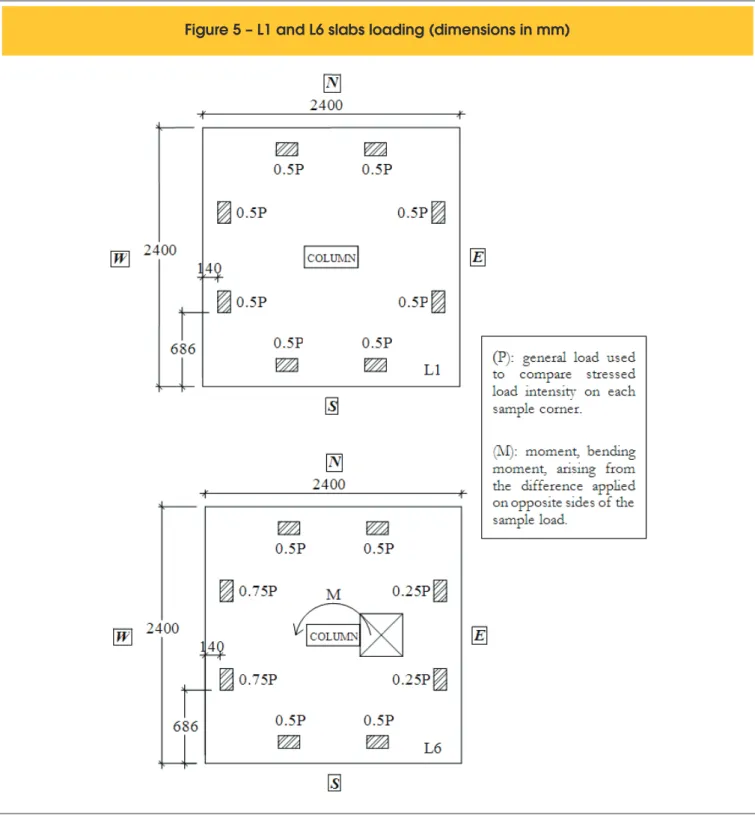
-ects engineering in lat slabs (when there are different loadings or different spans on either side of the column) - and also to study the applied moment intensity effects. In order to encourage the trans
-fer of the lexural moment in a certain direction, the applied load intensity was greater on one side of the sample. On slab L4, for ex
-ample, a load was applied designated as “2P”, which is the same as saying that the loading on this region was twice more than on others, except to the opposite side, which had no loading (charging designated as “0”) . However, the total vertical load (four corners sum of applied load) was the same in all slabs (“4P”). The load was applied from above through leaked hydraulic actuators. It was
placed on metal beams resting on the actuators, and on
distribu-tion steel beams of 100 mm x 200 mm x 20 mm, ixed on the slab plates according to Figure 1. Figure 5 shows the load supported by each distribution plate for slabs L1, without the moment transfer,
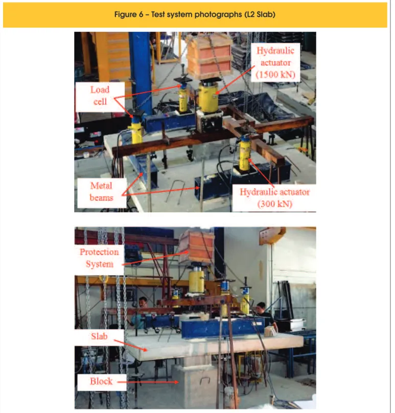
and L6 with moment transfer. Figure 6 shows photographs of the test system (slab L2). These actuators were anchored in four metal ties with 29 mm of diameter. The ties passed through the slab and steel beams through holes previously made, and were anchored
in the reaction slab. The reaction to loading occurred in the central
column, monolithically connected to the slab. The column was sup
-ported in the bottom on a cubic block of reinforced concrete with edges of 600 mm. The block was inserted to facilitate the displace -ment under the slab and it had the function of transmitting the test part reaction to the slab. Due to the moment transfer, column
pre-stressing was used in order to prevent rotation and also to simulate the loading of the column. The pre-stressing was done by a leaked hydraulic actuator with 1500 kN capacity, supported by a metal pre-stressing box (SAC 1045 steel). This actuator was anchored by a tie with 44 mm of diameter, passing through the metal pre-stressing box, the column and the block (hole protected by steel tubes on the column and block).
Table 3 – Equations used to calculate failure loads in flat slabs
Rules Slabs without shear reinforcement Check the crushing of the concrete strut
ACI-318 (2011)*
CEB – FIP (1990)
EC2 (2004)
NBR 6118 (2007)*
* – the failure load will be lowest one shown in equations application; Where:
f , f’ : resistance characteristic to concrete compression (MPa);ck c
bc : ratio between the longest side lengthon the lowest side of the column;
as : constant to the values: 40 for internal columns, 30 to edge columns and 20 for corner columns (for all slabs of this study as= 40);
gc: mitigation coefficient equal to 1.4 for NBR 6118/2007 and 1.5 for EC2 (2004), but as it is an experimental results verification, nosafety factor was adopted (gc=1.0);
reinforcement ratio in two orthogonal directions, reached using a column width dimension plus "3d" for each side (or to the slab edge, whether it is nearer).
y x
1
r
r
.r
r
=
=
(Equation 1) –
– – – – (Equation 2) (Equation 3) (Equation 4) (Equation 5) (Equation 6)
d
b
f
V
c cc
0
,
17
1
2
÷÷
' 0ø
ö
çç
è
æ
+
=
b
d
b
f
b
d
V
c s c' 00
2
083
,
0
÷÷
ø
ö
çç
è
æ
+
=
a
d
b
f
V
c=
0
,
33
c' 0(
100
f
)
u
d
d
200
1
0,12
P
sd÷
÷
r
ck 1/3 1ø
ö
ç
ç
è
æ
+
=
(
100ρ
f
)
ud
d
200
1
γ
0,18
V
1 ck 1/3c
Ed
÷
÷
ø
ö
ç
ç
è
æ
+
=
(
100
f
)
C'
d
d
200
1
0,13
F
Sd÷
÷
r
ck 1/3ø
ö
ç
ç
è
æ
+
=
Cd
(Equation 7)Negative lexural reinforcements were composed by orthogonal meshes with 12.5 mm of diameter bars and positioned near the upper edge of the slabs (15 mm covering). Figures 7 and 8 show lexural reinforcement used in the models 1 and 2, respectively. The positive lexural reinforcements used in model 1 was composed of an orthogonal mesh with 10 bars of 6.3 mm of diameter in two directions, spaced in each 24 cm, as shown in Figure 9. For model 2 samples, the bars coinciding with the opening position were cut, so that it was inserted, without replacement bars, as shown in Figure 9. The steel used was CA-50 and CA-60 types. In order to obtain these material mechanical properties, samples were tested as NBR 6152 (1992) [4]. Table 6 shows the characteristics (mechani -cal properties) of steels tested.
The concrete used was a self-compacting concrete (SCC), settled to reach 30 MPa (characteristic compression strength). Table 7 shows the
proportion of the materials used to produce one concrete cubic meter.
The slabs were shaped in steel formworks. A metal tube with
830 mm of length and 75 mm of diameter was embedded in each formwork, in the column center, for subsequent passage of the central tie; and four rectangular metal tubes with external mea
-sures 60 mm x 100 mm for later lateral passage of the ties. For slabs with openings shaping, molds with Expanded Polystyrene (Styrofoam) were made. Figure 10 shows photographs of metal
-lic formwork and reinforcement before L7 slab concreting and L1 and L2 moulded slabs. After concreting, water was placed on the slabs and they were covered with plastic sheets for seven (7) days. Water was replenished twice a day for the irst three days and once on remaining days.
3. Results
3.1 Vertical displacement
In Figures 11 and 12 are shown the graphs of vertical displacement
Table 4 – Control perimeters with openings
Rules Control perimeter
ACI-318 (2011)
EC2 (2004)
NBR 6118 (2007)
CEB – FIP (1990) –
The NBR 6118/2007 does not predict a reduction in the critical perimeter C, when there are openings. b – control perimeter for 0 slabs with distant openings up to 10h (h=slab total height) from the center of the column.
0,5d
Opening
0,
5
d
<
10h
b
OIf I >I , 1 2
u – control perimeter for 1 slabs with openings distant up to 6d to column face.
2 1 2
I
I
I
=
C, C' – perimeters control for slabs with openings distant up to 8d to column surface.
1,5
d
1,5
d
u
Opening
<
6
d
I
1<
I
2I
22d
2
d
< 8d
C
x position relative to the center of the slab, in each axis, for slabs L1 (without openings and without applied moment) and L3 (with open -ing and moment applied in the direction parallel to the largest side
of the column). The behavior in both directions was symmetrical in slab L1. In slab L3, there was rotation in WE direction where dis -placements in each side were opposed. However, in W side there was a displacement down, and up in E side. The W maximum dis -placements were on average 2.1 times higher on the maximum dis
-placement in E side. This was due to the applied load, which was “2P” intensity in W side, while the opposite side (E) has not received
a load. In the NS direction, the maximum displacements in N side were slightly higher, 0.07 mm on the load of 25 kN and 1.01 mm on the load of 200 kN.
3.2 Load and failure mode
Figure 4 – Tested slabs geometric characteristics - Models 1 and 2
TOP VIEW
COLUMN
200
500 HOLE 2400
A
B
400
400
400 300
SECTION AA
150
SECTION BB
200 500
MODEL 2
A B
TOP VIEW
COLUMN
200 500 2400
A
B
400 300
SECTION AA
150
SECTION BB
200 500
MODEL 1
B
A
Model used for slabs L1
All slabs were cracked by puncturing. Table 8 shows the main
characteristics of the slabs and their failure loads.
The L2 slab (Vu = 266 kN, Mu = 116.8 kN.m), without opening and
moment applied parallel to the longest side of the column, had a
38 % loss compared to L1 slab (reference slab). This failure load reduction was due to the lexural moment transfer from the slab to
the column in that sample.
The moment inluence on decreasing shear resistance could also be observed comparing L4 and L5 slabs. Both of them had parallel moment applied to the longest side of the column towards the 400 mm x 400 mm opening. The difference between the models was the applied moment intensity, which was higher on L4 slab. As a result, the latter showed a of 68 % loss compared to the reference slab, while on L5 slab the loss was lower, 50 %.
Comparing the slabs with openings and moment transfer (L3 to L7) with L2 slab, without opening and moment transfer, it
was observed that reducing the perimeter of the slab-column link (due to adjacent opening) does not result in load loss if the lexural moment is not applied towards the opening. The slabs L2 (Vu = 266 kN, Mu = 116.8 kN.m) and L3 (Vu = 250 kN, Mu = 113.7 kN.m), despite the last one having opening, slabs showed very close failure loads. It is also interesting to observe that when the moment intensity applied on the slab with opening was reduced, L6 slab (Vu = 305 kN, Mu = 65.8 kN.m), resulted in a failure load even greater than L2 slab without opening. This indicates that the transfer of slab lexural moment to the column is more damaging to the shear resistance, than the existence of adjacent openings to the column.
3.3 Cracking and surface failure
In slabs L1 and L2, the radial cracks initiated at the column.
Table 5 – Slabs loading L1 to L7
P P 0 2P P P 1.5P
0.5P P P
1.5P 0.5P P P 1.5P 0.5P
WITHOUT HOLE
WITH 1 HOLE 400X400 mm
W
IT
H
O
U
T
M
O
M
EN
T
W
IT
H
M
O
M
EN
T
L1
L2
L3
L4
L5
L6
L7
2P 0 P P P P 0 2P 24 00 2400 20 0 500 400
d
fc
Mu
Vu
Units:
r
mm
MPa
kN.m
kN
%
d = 120
fc = 44.7
Mu = 0,0
Vu = 426
r = 1.22
d = 122
fc = 44.1
Mu = 116.8
Vu = 266
r = 1.19
d = 125
fc = 42.8
Mu = 113.7
Vu = 250
r = 1.17
d = 123
fc = 44.6
Mu = 59.0
Vu = 137
r = 1.20
d = 122
fc = 44,5
Mu = 27.0
Vu = 213
r = 1.22
d = 124
fc = 45.6
Mu = 65.8
Vu = 305
r = 1.19
d = 121
fc = 46.8
Mu = 44.5
Vu = 260
r = 1.24
WITHOUT HOLE
In slabs L3, L6 and L7, such cracks initiated at the same time, in the column and the openings corners. In slabs L4 and L5, the radial cracks initiated at the corners of the openings. These cracks widened toward the slabs edges. Subsequently or at the same loading, circumferential cracks appeared. The slabs cracking view is shown in Figure 13.
The failure surfaces, slabs L1 to L7, started on the slab upper sur
-face (tensioned sur-face) and extended towards the column-slab
junction, the slab underside (compressed surface), leading to a variety of inclinations, which originated the shear punching “cone”. In slabs with opening, it was possible to see the failure surface
formation through itself. The surface slope in relation to the
un-derside of the slab L1 ranged between 31° and 53°. In L2 slab,
failure surfaces occurred with slopes ranged from 27° to 85°. In
L3 slab, this variation was from 26° to 32°. In slabs L4 to L7, varia
-tions were, respectively, from 22° to 67°, 24° to 41°, 17° to 36° and
2° to 41°. Figures 14 and 15 show the surfaces failure conigura
-tion for slabs L1 to L4.
3.4 Comparison between experimental
and theoretical results
Rules for estimated loads allow the concrete strength, for the test date, as equal to concrete strength characteristics (fck ≅ fc). Because
it is a scan of experimental results, no safety factor was adopted.
The results estimated by some rules ended up being lower to those experimentally found. It is worth noting that in this study, the slabs were subjected only to the efforts of shear punching and moment transfer, and the codes are committed to predict many other condi
-tions not included in the tests, and that may happen in a real situa
-tion, such as possible asymmetric loads concentrated near the col
-umn, horizontal forces, cracking of concrete at early ages, adding arrows due to charges maintenance for a long period, unfavorable
20
f
12.
5m
m
,c
=320c
m
236
236
10
f
16.0mm,
c = 80cm
10.8
33.5
d
= 12.3
12 12.3
30
SECTION BB
B
SECTION AA
50
20
40
30
10.8 12
15
33.5
30
5
45
15
6 f
5.0mm,
c = 130 cm
Hole (passage of the tie rod)
B
A
A
18.5 14 12 12 12 12 12 12 16.5 12 12 12 12 12 12 14 18.5
10 12 11 11 11 11 11 11 11 11 11 11 11 11 11 11 11 11 11 12 10
26
f
12.5mm, c/ 11cm - 320cm
13 10 10 10 16.5 15 16.5 10 10 10 13 19 19
B
A
B
A
21 f 12.5mm (contínuing) 2x4 - Pairs
of bars
5 - Pairs of bars
10 10 10 10 8 8 8 8 8
22
f
12
.5
m
m
(co
nt
ín
ui
ng
)
Hole (passage of the tie rod)
12 12 12 12 17
17 8.5 8.5
8.5
19 19
NEGATIVE REINFORCEMENT L3 TO L7
12
25 51.5
40
30
96 12.3
33.5
33.5 10
.8
10
.8
10
.8
33.5 33.5 10
.8
12
141.5
30
SECTION AA
12
30 25 12
15 12.3
SECTION BB
15
96
14.512 26
15 2
(Model 1 - L1 and L2) and slabs with opening (model 2 - L3 to L7 (cm))
POSITIVE REINFORCEMENT L1 AND L2
10
f
6.3 c/ 24cm - length=230cm
in both directions
24
16
f
6.3 c/ 24cm - length=230cm
in both directions
*bars cut the hole
2 bars
length=137cm
length=47cm
2 bars
2x2 - Pairs of bars
length =92cm
21 22
240
22 22 22 22 22 22 22 22 21
21
22
22
22
22
22
22
22
22
22
Model
Model 1
Without hole
slabs L1 and L2
2
load construction conditions due to re-shoring, heavy equipment, among others. Figure 16 shows graphically the comparison be
-tween “experimental loading” / “estimated loading” (L1 slab) and “experimental stress” / “estimated stress” (slabs L2 to L7) relations. The “estimated load” and “estimated stress” were obtained with the
studied standards usage.
The CEB-FIP/MC1990 [7] does not provide speciications about openings use in lat slabs. The failure load was calculated only for the L1 and L2 slabs.
The NBR 6118:2007 [5], as well as other standards showed re
-sults against safety for L1 slab (reference slab), and the ACI-318: 2011 [1] was the closest one to the experimental result. For L2 slab, without openings, estimated standards were similar to those experimentally obtained. The NBR 6118:2007 [5] had “experimen
-tal stress” / “estimated stress” relation equal to 0.97. The ACI-318: 2011 [1] was the most conservative standard: it showed “experi
-mental stress” higher than “estimated stress” in 25 %. For L3 and L6 slabs, both with moment applied in the opposite direction to the opening, all standards presented estimates for safety, highlight
-ing the ACI-318: 2011 [1] and EC2/2004 [12], which showed the most conservative results, related to “experimental stress” / “es
-timated stress” ranging between 1.26 and 1.54. For NBR 6118: 2007 [5] this ratio ranged between 1.10 and 1.28. In slabs L4 and L5, both with moment applied towards the opening, most of the rules showed estimate against safety, including NBR 6118:2007 [5], with ratio “experimental stress” / “estimated stress “ ranging from 0.66 and 0.68. The only exception was ACI-318: 2011 [1], which showed results favoring safety for L4 slab. In slab L7, only ACI-318: 2011 [1] showed results favoring safety (ratio “experi
-mental tension” / “estimated stress” equal to 1.17), although the estimated EC2/2004 [12] was fairly close to the experimental result (ratio “experimental stress” / “estimated stress” equal to 0.97). For the same slab, the NBR 6118: 2007 [5] showed a correlation of 0.84 against the security.
3.5 Comparison between experimental results
and SOUZA’s results [24]
3.5.1 Vertical displacement
The slabs vertical displacements behavior pattern in this study was similar to SOUZA’s Slabs [24], verifying: 1) openings that led to an
increase of vertical displacements around them; 2) in the direction
that the moment was applied, there was a spin and the most load
-ed side displac-ed towards the load application, while the opposite
edge displaced opposite the stressed load direction; 3) the
direc-tion to which the moment was not applied, displacements showed by all slabs were similar to those obtained in the reference slab L1, without openings and without moment; 4) in slabs with openings and with parallel moment applied to the longest side of the column,
openings did not result in large differences of displacements on
the side with opening, in relation to the slab without opening with moment applied in the same direction; 5) slab with opening and
parallel moment applied to the column shortest side is the one that
shows greater displacements at the most loaded edge. The prob
-able cause would be slab-column connection inertia, being this parallel one lower than the column shortest side.
3.5.2 Failure load
In this study slab L6 (Vu = 305 kN, Mu = 65.8 kN.m, fc = 45.6 MPa, d = 124 mm, ρ = 1.19 %), with a 400 mm x 400 mm opening
adjacent to the smallest column side and situated on the stressed edge, with parallel moment applied toward to the longest side of the column, had a failure load very close to SOUZA’s L12 slab [24] (Vu = 319 kN, Mu = 74.4 kN.m, fc = 37.8 MPa, d = 123 mm, ρ =
1.48 %), with a 200 mm x 200 mm opening adjacent to the lowest side of the column, placed on the stressed edge, with a moment applied towards the longest parallel direction column side. This means that a 200 mm x 200 mm opening adjacent to the smallest Lot Diameter(mm) (MPa)fy (MPa)fu ey (GPa)Es Use of bar
(mm/m) 1 2 1 2 3 1 6.3 6.3 12.5 12.5 12.5 16.0 649 673 595 623 583 595 766 807 739 770 710 739 273 213 200 205 236 200
Lower flexural reinforcement and L4 slab column stirrups Lower flexural reinforcement and
L1 to L3 and L5 to L7 slabs column stirrups Top flexural reinforcement L4 slab Top flexural reinforcement L1 to L3 slabs Top flexural reinforcement L5 to L7 slabs Longitudinal reinforcement of all slabs columns 2.2 2.9 2.7 2.4 2.4 2.7
Table 7 – Composition of concrete
3
per m
Material
Weight (kg)
Cement (CPII F32)
Natural sand (maximum dimension:
4.8 mm)
Artificial sand (maximum dimension:
4.8 mm)
Gravel 0 (maximum dimension:
12.5 mm)
Gravel 1 (maximum dimension:
19.0 mm)
Water
405
410
270
510
510
200
side of the column and compressed by the applied moment can be as damaging to the failure load as a 400 mm x 400 mm opening adjacent to the lowest column side and tensioned by the moment applied to the variables used in this study. It is noteworthy that all
SOUZA’s slabs [24] have identical geometric characteristics to the slabs of this study, varying their dimension (200 mm x 200 mm, 200 mm x 300 mm or 400 mm x 400 mm) and openings location
(parallel to the longest or shortest column side).
For slabs with failure parallel moment applied to the shortest col
-umn side, the use of two 300 mm x 200 mm openings adjacent to
the longest side of the column is less damaging to the failure load
than a 400 mm x 400 mm opening adjacent the lowest column side. In this study, it was observed a 20% load loss in slab L7 (Vu = 260 kN, Mu = 44.5 kN.m, fc = 46.8 MPa, d = 121 mm, ρ = 1.24
%) in relation to SOUZA’s L18 slab [24] (Vu = 322 kN, Mu = 53.1 kN.m, fc = 37.3 MPa, d = 126 mm, ρ = 1.05 %), with two 300 mm x
200 mm openings adjacent to the column longest side.
For slabs with failure moment applied parallel to the longest col -umn side, the partial slab-col-umn connection loss in the region on
the corners caused by two openings of 200 mm x 200 mm adjacent
to the smallest side of the column, is less damaging to the failure
load than a single 400 mm x 400 mm opening adjacent to the col
-umn lowest side and located in the compressed edge. Regarding SOUZA’s L10 slabs [24] (Vu = 189 kN, Mu = 83.0 kN.m, fc = 34.2 MPa, d = 123 mm, ρ = 1.24 %), with two openings of 200 mm x 200
mm adjacent to the lowest side of the column, the L4 slab in this
Figure 11 – Vertical displacements measured by D1 to D12 dial gauges in slab L1
V
u: last failure load ; M
u: last failure moment;
P: general load used to compare load intensity on each
sample corner;
0: null load value representing the sample which received no load.
study (Vu = 137 kN, Mu = 59.0 kN.m, fc = 44.6 MPa, d = 123 mm, ρ
= 1.20 %), with 400 mm x 400 mm opening adjacent to the smallest side of the column and located in the compressed edge, showed a 28 % lower failure load. Table 11 presents the characteristics of
mentioned slabs.
3.5.3 Concrete and lexural reinforcement deformations It can be observed that such slabs in this study as in SOUZA’s slabs [24] that the reinforcement low was reached on several points, mainly in the columns region, as expected. The discontinu
-ous lexural reinforcement bars (which ended in the opening) were
little solicited, indicating that these reinforcements are not effective against bending and therefore punching. Concerning the concrete,
Figure 12 – Vertical displacements measured by D1 to D12 dial gauges in slab L3
V
u: last failure load; M
u: last failure moment ;
P: general load used to compare load intensity on each
sample corner;
0: null load value representing the sample which received no load.
4. Conclusions
Regarding the failure load, it was conirmed through bibliography, which refers to shear punching resistance reduction, against the mo
-ment transfer from the slab to the column (L2 slab without opening, with applied moment, showed failure load 38% lower than L1 refer
-ence slab, without opening and without applied moment). In slabs with
openings, the moment transfer to the column led to a decrease in
resistance between 28% and 68%, relative to the L1 slab reference. However, the worst situations regarding opening slabs resistance loss, in slabs adjacent the column, and with moment transfer, occur when the moment is towards the opening region, which is more fragile
and has the same volume of concrete to resist compressions in the
bottom layer of the slab. When the moment is not applied towards the opening region, the failure load is very close, or even higher than a slab without opening (with moment transfer), as comparison between the slab L2 (Vu = 266 kN, Mu = 116.8 kN.m) with L3 slabs (Vu = 250 kN, Mu = 113.7 kN.m), with opening and moment applied in opposite direction to the opening region, and L6 (Vu = 305 kN, Mu = 65.8 kN.m),
pecially about failure to slabs punching, fragile and no warning rup
-tures, comparison of experimental results in this study with rules estimates showed that the rules requirements are not meeting the desired security. The results were not satisfactory, some even against the security, especially when the moment is applied to the parallel direction of the column largest dimension towards the opening region. As shown in Table 9, ACI-318: 2011 [1] showed that the standard was more conservative, with arithmetic average
of relations τu / τr1 equal to 1.21, and EC2/2004 [12] was the clos
-est to experimental results, with arithmetic average of relations νu / νR,c equal to 1.06, for slabs with applied moment. Regarding
L1 reference slab, with no opening and no applied moment, all rules mentioned showed estimates against the safety, according to Table 10. The code that showed closest experimental result was the ACI-318: 2011 [1] with respect Vu / VCalc equal to 0.92.
5. Thanks
[01] ACI COMMITTEE 318. Building Code Requirements for Re
-inforced Concrete and Commentary - ACI 318/2011. Farm
-de Brasília 2000, 142 p.
[03] ANDRADE, M. A. S. de. Punção em lajes cogumelo – Estudo do Posicionamento da Armadura de Cisalhamento em Relação
Table 8 – Slabs failure characteristics and loads
Slab f c
(MPa) (mm)Hole (mm)d (kN)V u (KN.m)M u (m)eu VV /u, L1u r
(%) and loadingGeometry
L1 L2 L3 L4 L5 L6 L7 44.7 44.1 42.8 44.6 44.5 45.6 46.8 – – 1 400x400 1 400x400 1 400x400 1 400x400 1 400x400 120 122 125 123 122 124 121 426 266 250 137 213 305 257 0.0 116.8 113.7 59.0 27.0 65.8 41.0 – 0.440 0.455 0.430 0.127 0.216 0.160 1.00 0.62 0.59 0.32 0.50 0.72 0.60 1.22 1.19 1.17 1.20 1.22 1.19 1.24
P
P
P
P
0
P
P
2P
0
2P
P
P
P
P
0
2P
0,5P
1,5P
P
P
P
P
1,5P
0,5P
1,5P
0,5P
P
P
f : cylinder compressive strength of concrete; r: reinforcement ratio; V : last load of failure; M : last moment of failure; c u u
Figure 15 – Failure surfaces configuration in slabs L1 and L2
Slab
Failure Surface
Failure Mode
L3 (with one
hole of 400x400 mm and moment with EW direction)
N
S
W E
Vu = 250 kN Mu = 113.7 kN.m
500
E W d = 125 mm
200 N
S 500
E W d = 125 mm
260 40 260 60
100 90
160
150
Adjacent
Punching Shear
L4 (com um
furo de 400x400 mm e momento
com sentido
WE)
N
S
W E
Vu = 137 kN Mu = 59.0 kN.m
500
E W d = 123 mm
200 N
S 500
E W d = 123 mm
30 50 30
40
300
160
Adjacent
Punching Shear
(
Vu): failure load of theslab;
(Mu): failure moment of
the slab;
(d): slab effective height;
Figure 16 – Comparison between experimental load and estimated load
relations (slab L1) and experimental stress and estimated stress (slabs L2 to L7)
L1
L2
L3
L4
P
P
P
P
0
P
P
2P
2P
0
P
P
P
P
0
2P
L5
L6
L7
0,5P
1,5P
P
P
P
P
1,5P
0,5P
1,5P
0,5P
P
P
à Armadura de Flexão. Dissertação de Mestrado, Escola de Engenharia Civil, Universidade Federal de Goiás, 1999, 156 p. [04] ASSOCIAÇÃO BRASILEIRA DE NORMAS TÉCNICAS.
NBR 6152:1992 – Materiais Metálicos – Determinação das Propriedades de Tração. Rio de Janeiro, 1992.
[05] ASSOCIAÇÃO BRASILEIRA DE NORMAS TÉCNICAS. NBR 6118:2003 – Projeto de Estruturas de Concreto - Pro -cedimento. Rio de Janeiro, 2007.
[06] BORGES, Liana de Lucca Jardim; MELO, Guilherme Sales Soares de Azevêdo; GOMES, R. B.; REGAN, P. E. Punching shear of reinforced concrete lat plates with openings. ACI
Structural Journal, v. 110, p. 547-556, 2013.
[07] CEB-FIP (1990). CEB-FIP Model Code 1990: Final Draft. Bulletin D’Information, Committe Euro-International du Be
-ton, Lausanne, July. 1991.
[08] CARVALHO, E. M. L. Puncionamento de Lajes Protendidas. Dissertação de Mestrado, COPPE-UFRJ, Rio de Janeiro,
1982.
[09] COELHO, A. E. G. Puncionamento em Lajes Cogumelo de Concreto Armado com Resistência de 30 MPa e Armadura de Cisalhamento Vertical e Inclinada. Dissertação de Mestrado, Faculdade de Tecnologia, Departamento de Engenharia Civil e Ambiental, Universidade de Brasília, 1999, 133 p.
[10] CORDOVIL, F.A.B. Punção em Placas de Concreto Armado. 1995, 393p. Tese de Doutorado. Departamento de Engen
-haria de Estruturas e Fundações, Escola Politécnica da Uni
-versidade de São Paulo, 1995.
[11] DIAS, D. P. Reforço ao Puncionamento em Lajes-cogumelo. Dissertação de Mestrado, COPPE/UFRJ, Rio de Janeiro,
[12] EUROCODE 2. Design of concrete structures – Part 1: Gen
-eral Rules and Rules for Buildings. European Prestandard ENV 2004-1-1:2004. European Committee for Standardiza -tion, Brussels, 2004.
[13] GOMES, R. B.; REGAN, P. E. Punching strength of slabs re
-inforced for shear with offcuts of rolled steel I section. Maga
-zine of Concrete Research, London, United Kingdom, v. 51,
n.2, p. 121-129, 1999.
[14] GOMES, R. B; REGAN, P. E. Punching resistance of RC lat slab with shear reinforcement. Journal of Structural En
-gineering (New York, N.Y.), EUA, v. JUNE, n.vol.125, p.
684-692, 1999.
[15] GOMES, R. B.; ANDRADE, M.A.S. de. Punching in Rein
-forced Concrete Flat Slabs with Holes. In: Proceedings of Developments in Computer Aided Design and Modelling for Structural Engineering. Edinburgh-UK, pp.185-193, 1995. [16] HANSON, N.W.; HANSON, J.M. Shear and Moment Trans
-fer Between Concrete Slabs and Columns. Journal. PCA Research and Development Laboratories. Vol. 10, no 1, pp
2-16, 1968.
[17] OLIVEIRA, D. R. C. Análise Experimental de Lajes Cogu -melo de Concreto de Alta Resistência com Armadura
Incli-Table 9 – Comparison between experimental stress and estimated stress
relations by the rules, for L2 to L7 slabs, with moment transfer
Slab Vu
(kN) (kN.m)Mu
CEB
1990 [7] 2004 [12]EC2 ACI –3182011 [1] NBR 61182007 [5]
tu/tR nu/nR,c nu/nu(AB) tu/trl
L2 L3 L4 L5 L6 L7 266 250 137 213 305 260 Average Standard deviation
Coef. var. (%)
116.8 113.7 59.0 27.0 65.8 44.5 0.98 – – – – – – – – 1.12 1.47 0.79 0.77 1.26 0.97 1.06 0.27 26.0 1.25 1.54 1.04 0.93 1.34 1.17 1.21 0.22 17.9 0.97 1.28 0.68 0.66 1.10 0.84 0.92 0.24 26.2
V : last load of failure; M : last moment of failure; u u tu, nu: experimental rupture stress; tR: estimated failure stress by CEB-FIP/MC1990
[7] and the NBR 6118:2007 [5]; nR,c: estimated failure stress by EC2/2004 [12]; nu(AB) : estimated failure stress by
ACI-318:2011 [1] and NBR; Coef. Var: Coefficient of variation.
Table 10 – Comparison between experimental load and estimated
load relations by the rules, for L1 slab without moment transfer
Slab Vu
(kN)
CEB
1990 [7] 2004 [12]EC2 ACI –3182011 [1] NBR 61182007 [5]
nu/ncalc nu/ncalc nu/ncalc nu/ncalc
L1 426 0.78 0.89 0.92 0.77
V : last load of failure; V : last estimated failure load by CEB-FIP/MC1990 [7], EC2/2004 [12], ACI -318: 2011 [1] u calc and NBR 6118: 2007 [5].
nada de Punção. Dissertação de Mestrado, Faculdade de Tecnologia, Departamento de Engenharia Civil e Ambiental, Universidade de Brasília, 1998, 137 p.
[18] OLIVEIRA, D. R. C. Análise Experimental de Lajes Cogume
-lo de Concreto Armado com Pilares Retangulares. Tese de Doutorado, Faculdade de Tecnologia, Departamento de En
-genharia Civil e Ambiental, Universidade de Brasília, 2003,
214p.
[19] PINTO, R. C. A. Punção Assimétrica em Lajes. 1993, 145p. Tese de Mestrado, Engenharia Civil, COPPE/UFRJ, 1993. [20] REGAN, P. E. Design for Punching Shear. The Structural En
-gineer, vol. 52, n° 6, p. 197-207, June, 1974.
[21] REGAN, P.E. Punching Tests of Reinforced Concrete Slabs with and without Shear Reinforcement with Openings Adja
-cent to Columns. 35 Marylebone Road London NW1 5LS. School of the Built Environment, University of Westminster, London, July. 1999.
[22] SANTOS, V. C. F. Resistência ao Puncionamento de Lajes Cogumelo de Concreto Armado. Projeto Final de Gradu
-ação, UnB, 1995, 48p.
Table 11 – Characteristics and slabs failure loads in this study with SOUZA's slabs [24]
Slab f c
(MPa) (mm)Hole (mm)d (%)r and loadingGeometry (kN)V u (KN.m)M u (m)eu
L6
L12*
L7
L18*
L4
L10*
45.6
37.9
46.8
37.3
44.6
34.2
305
319
257
250
137
189
65.8
74.4
41.01
13.7
59.0
83.0
0.216
0.233
0.160
0.454
0.430
0.439 124
123
121
126
123
123
1.19
1.48
1.24
1.05
1.20
1.48 1
400x400
1 200x200
1 400x400
2 300x200
1 400x400
2 200x200
* SOUZA's slabs study [24];
f : resistance to stressed concrete; d: slab effective height; r: reinforcement ratio; V : last load of failure; M : last moment of c u u failure; e : load eccentricity (ratio M /V ). P: general load used to compare stressed load intensity on each sample corner.u u u
P
P
1,5P
0,5P
P
0,5P 1,5P
P
1,5P
0,5P
P
P
1,5P
0,5P
P
P
P
P
0
2P
0
P
P
2P
Laje-Pilar de Lajes Lisas, com Furos Adjacentes ao Pilar: Es
-tudo Experimental e Comparações com a NBR 6118:2003. In: 53º Congresso Brasileiro do Concreto CBC2011, 2011, Florianópolis. Anais do 53º Congresso Brasileiro do Con -creto CBC 2011. v. 1. p. 1-16.
[24] SOUZA, Raphael Miranda de; MELO, Guilherme Sales Soares de Azevêdo; GOMES, Ronaldo Barros. Estudo de
ligações laje-pilar de lajes lisas, com furos adjacentes ao pilar e transferência de momento: estudo experimental e compara
-ções com a NBR 6118:2003. In: 53º Congresso Brasileiro do Concreto CBC 2011, 2011, Florianópolis. Anais do 53º Con -gresso Brasileiro do Concreto CBC 2011, 2011. v. 1. p. 1-16.
Mestrado, Esc. de Eng. de São Carlos, USP, , 1981, 241p. [26] TRAUTWEIN, Leandro Mouta; BITTENCOURT, Túlio
Nogueira; GOMES, R. B.; DELLABELLA, J. C.. Punching strength of lat slabs with unbraced shear reinforcement. ACI
Structural Journal, v. 108, p. 197-205, 2011.
[27] VARGAS, E. N. Z., Punção em Lajes Cogumelo de Concreto de Alta Resistência Reforçado com Fibras de Aço. Disserta
![Table 1 – Characteristics and failure loads of BORGES' slabs [6]](https://thumb-eu.123doks.com/thumbv2/123dok_br/18860574.417858/3.892.70.829.725.1011/table-characteristics-failure-loads-borges-slabs.webp)
![Figure 2 – Tested slabs models by BORGES [6] – mm](https://thumb-eu.123doks.com/thumbv2/123dok_br/18860574.417858/4.892.64.837.314.1133/figure-tested-slabs-models-by-borges-mm.webp)
![Figure 3 – Tested slabs characteristics by SOUZA [23] - mm](https://thumb-eu.123doks.com/thumbv2/123dok_br/18860574.417858/6.892.66.849.322.1134/figure-tested-slabs-characteristics-souza-mm.webp)