Punching strength is a critical point in the design of lat slabs and due to the lack of a theoretical method capable of explaining this phenomenon, empirical formulations presented by codes of practice are still the most used method to check the bearing capacity of slab-column connections. This paper discusses relevant aspects of the development of lat slabs, the factors that inluence the punching resistance of slabs without shear reinforcement and makes comparisons between the experimental results organized in a database with 74 slabs carefully selected with theoretical results using the recommendations of ACI 318, EUROCODE 2 and NBR 6118 and also through the Critical Shear Crack Theory, presented by Muttoni (2008) and incorporated the new ib Model Code (2010).
Keywords: lat slab, punching shear, reinforced concrete, codes.
O dimensionamento à punção é um ponto crítico no projeto de lajes lisas e devido à falta de um método teórico capaz de explicar este fenômeno a veriicação da capacidade resistente de ligações laje-pilar é feita normalmente utilizando-se as recomendações de normas de projeto. Este artigo discute aspectos relevantes do surgimento do sistema de lajes lisas, dos fatores que inluenciam na resistência à punção de lajes sem armadura de cisalhamento e faz comparações entre os resultados experimentais de um banco de dados com 74 lajes cuidadosamente selecionadas com resultados teóricos utilizando-se as recomendações das normas ACI 318, EUROCODE 2 e NBR 6118 e também através da Teoria da Fissura Crítica de Cisalhamento, apresentada por Muttoni (2008) e incorporada à nova norma ib Model Code (2010).
Palavras-chave: lajes lisas, punção, concreto armado, normas.
Punching strength of reinforced concrete lat slabs
without shear reinforcement
Punção em lajes lisas de concreto armado sem
armadura de cisalhamento
P. V. P. SACRAMENTO a M. P. FERREIRA b [email protected]
D. R. C. OLIVEIRA c
G. S. S. A. MELO d
a Mestrando em Engenharia Civil, Universidade Federal do Pará, Belém, Pará, Brasil.
b Professor, Faculdade de Engenharia Civil, Universidade Federal do Pará, [email protected], Belém, Pará, Brasil. c Professor, Faculdade de Engenharia Civil, Universidade Federal do Pará, [email protected], Belém, Pará, Brasil.
d Professor, Departamento de Engenharia Civil e Ambiental, Universidade de Brasília, [email protected], Brasília, Distrito Federal, Brasil.
Received: 30 Mar 2012 • Accepted: 28 Jun 2012 • Available Online: 02 Oct 2012
Abstract
1. Introduction
Flat slabs are those which are directly supported on columns wi -thout capitals. They can be considered as a good option for con-crete buildings since they may reduce the construction time due to the simpliication of forms and rebars and especially by attributing greater lexibility in layout of loors. The design of slab-column con -nection is the most critical point in the design of lat slabs, because of the concentration of shear stresses in this region that can lead to punching, which is a localized failure mode that can occur wi -thout signiicant warnings and may lead the whole structure to ruin through the progressive collapse. Figure 1a shows an example of punching failure recorded by Ferreira [1]. One way to ensure local ductility and prevent progressive collapse of lat slabs is through the use of post-punching reinforcement as those shown in Figure 1b, which must be designed to carry the vertical reaction in the column, and must be detailed in order to ensure that they are sufi -ciently anchored beyond the region of the possible punching cone. Since tests carried by Elstner and Hognestad [2] many other stu -dies have been conducted aiming to understand the behavior and strength of lat slabs. Some theoretical methods were proposed but none was generally accepted because they were not able to accurately estimate the punching resistance of slab-column con-nections and at the same time explains the phenomenon with all its variables. Thus, the design of lat slabs to the punching is normally done using recommendations presented by codes of practice for design of concrete structures, which are essentially empirical. Recently Muttoni [3] presented a new theoretical approach called Cri -tical Shear Crack Theory (CSCT), which is able not only of predicting the bearing capacity of slab-column connection, but also of estimating their behavior in service (rotation, displacements and strains). This the-ory is based on the idea that the punching resistance decreases with increasing rotation of the slab, and has recently been embodied in the irst draft of the new ib Model Code [4,5], which was presented in 2010, and has come to replace the old CEB-FIP MC90 [6]. This paper aims to evaluate this method by comparing its theoretical results with experi -mental results of tests of 74 reinforced concrete lat slabs without shear reinforcement carefully selected (see section 6 of article) to form a
lar-ge database, with specimens with a signiicant variation of parameters such as the effective depth, lexural reinforcement ratio and compressi -ve strength of concrete. These experimental results were also compa -red with the theoretical results obtained by using the recommendations of ACI 318 [7], EUROCODE 2 [8] and NBR 6118 [9].
2. Historical development of lat slabs
There is controversy about who idealized the lat slabs structural system. Gasparini [10] states that the credit for the development of this system should be given to George M. Hill, an engineer who re -portedly designed and built constructions like iltration plants and storehouses in different regions of the United States between 1899 and 1901. He emphasizes, however, that C A. P. Turner, an Ameri -can inventor and engineer, was the one responsible for demonstra -ting that these slabs were reliable with numerous buildings construc -ted, the irst being Johnson-Bovey building in the city of Minneapolis in 1906. Turner’s “mushroom” slab were characterized by the pre -sence of capitals in the slab-column connection and also by the use a cage comprising bars of 32 mm diameter, working as shearheads. Furst and Marti [11] attributed the invention of this system to the Swiss engineer Robert Maillart, most famous for his works with bridges than the development of such structural system. According to these researchers, Maillart would have designed the system in 1900, but had only completed his tests in 1908, coming to get the patent of the system in 1909. Kierdorf [12] points out that while the system was developed independently in the United States and Switzerland, with the prohibition of the use of reinforced concre -te in Russia in 1905, the engineer Arthur F. Loleit designed and implemented a factory nearby at the Moscow in 1907 in lat sla -bs, have been the irst of several buildings in slabs without beams made by him in Russia. The author further comments that if his presentations of “beamless” construction at the regular meeting of cement specialists in Moscow (1912) and to the Russian Society for Materials Research (1913) had been documented, and also if WWI (1914-1918) had not happened, Loleit would certainly have presented his work to a broader public. Some details on the deve -lopment of lat slabs can be seen in Figure 2.
Figure 1 � Punching shear failure in slabs without shear reinforcement (Ferreira [1])
Punching shear failure Without
post-punching reinforcement
With
post-punching reinforcement
C. A. P. Turner�s ��us�roo�� slabs (�as�arini [10]) A
Tests carried by Maillart (Furst e Marti [11])
Factory built in Russia in 1910 (Kierdorf [12]) B
formation of bending and shear cracks to divide the slab into seg -ments, and, assuming that the region external to the punching cone presented rigid body rotations around a point away by a distance x (height of the slab’s neutral axis) either vertically and horizon -tally in relation to the column faces, it related the ultimate punching strength with the compressive strength of an imaginary shell coni -ned between the column and the critical shear crack. This method was a relevant original contribution, being the irst rational theory presented, but at the time his equations were considered complex and the accuracy observed for the theoretical results did not justify its use over the existing empirical methods.
One year after this publication, Moe [15] published a report of a large series of tests analyzing several variables, including the cases of unbalanced moments in slab-column connections, and his work re -mains the basis for the recommendations of ACI 318 [7]. After that, many works have been conducted and many contributions were made to the better understand of the punching shear phenomenon and also for the deinition of the inluence of the involved parameters in the ultimate strength of the slabs, as will be shown below.
3. Factors that inluence in
the punching resistance
Results of several tests indicate that the punching resistance of reinforced concrete lat slabs without shear reinforcement is mainly inluenced by the compressive strength of concrete (fc), the tensile lexural reinforcement ratio (ρ), the size and geometry of the colu -mn and also the size effect (ξ) which is a coeficient that takes into account the reduction of the nominal shear strength of the slab by increasing the effective depth (d). The inluence of each of these parameters is discussed below based on relevant test results.
3.1 Strength of Concrete
The shear failure of a concrete element without shear reinforcement is governed, among other factors, by the tensile strength of concre-te. Establishing the compressive strength of concrete is the initial step in the design process of a concrete structure and also norma-tive formulations tend to relate the tensile strength of concrete as a Many obstacles had to be translated until the lat slabs could be
used safely and economically. Initially there was strong discussion about the theoretical methods for the determination of the forces on a system without beams and these slabs were used in manner practically empirical, observing signiicant variations in the amount and arrangement of the lexural reinforcement between the compe -ting systems. Furst and Marti [11] highlight that the irst well foun -ded theory for calculation of forces on loors without beams was published only in 1921, with the work of Westergaard and Slater, whom by using the method of inite differences were able to treat different load cases, the inluence of the stiffness of the columns and capitals.
It was also necessary to establish rules to normalize the use of lat slabs, which became increasingly popular. That was possible only in 1925 with the publication of American code (ACI) for the design of reinforced concrete structures, which was the irst to present recommendations for lat slabs. These irst recommendations were based on experimental tests carried out in the USA like those from Talbot [13], who tested footings in University of Illinois, as shown in Figure 3.
However the footings tested by Talbot [13] were very thick com -pared to the mushroom slabs at that time, and therefore, these results were not adequate in terms of the punching strength. Trying to ill this and other gaps, Elstner and Hognestad [2] tested 39 sla -bs, aiming to evaluate the inluence of important variables such as the lexural reinforcement ratio, concrete strength, amount of compression reinforcement, support conditions, size of columns and amount and distribution of shear reinforcement in the punching strength of lat slabs. They concluded that practically all of these factors have strong inluence on the shear strength of lat slabs, except for the increase in the compression reinforcement ratio, which was considered by them as having a small inluence on the ultimate strength of tested slabs.
Subsequently were published two of the most important papers on punching. Kinnunen and Nylander [14] presented a mechani -cal model that sought to explain the punching failure mechanism and predict the strength of slab-column connections. This model was based on experimental observations obtained after performing an extensive experimental program. The model was based on the
function of its compressive strength. These are the reasons why it is common to observe that experimental researches correlate the shear strength to the compressive strength of concrete.
Graf [16] was among the irst to try to assess the inluence of con -crete strength in the punching resistance, concluding that there was not a linear relationship between the increases of the strength of a slab-column connection with the increase of concrete strength. Moe [15] proposed that the punching resistance could be expres -sed with a function proportional to the square root of the compres -sive strength of concrete, proposition until today used by the ACI. However, the results of recent research, such as Hallgren [17], which analyzed concrete slabs with high strength concrete, indi -cate that in these cases, relating the punching resistance with a function proportional to the square root of the compressive streng-th of concrete tends to overestimate its inluence. For streng-this reason ACI limits the use its expression for concrete with strengths up to 69 MPa or 10.000 psi.
Marzouk and Hussein [18] analyzed slabs with high strength con -crete varying the effective depth of the slab and also the lexural reinforcement ratio, concluding that a function proportional to the cube root of the concrete strength better represents the trend of the experimental results, what is also recommended by Hawkins et al. [19] and Regan [20]. Figure 4 shows a graph made in order to evalu -ate the inluence of the concrete strength in the punching resistance of lat slabs. It was compared the trend obtained by using a function proportional to the cube root of the compressive strength of concre-te (as proposed by the equations of Eurocode 2) with experimental results from the database, observing a good correlation between the experimental results and the function evaluated.
3.2 Flexural Reinforcement Ratio
The lexural reinforcement ratio (ρ) is deined as the ratio betwe -en the area of t-ensile lexural reinforcem-ent (As) and the area of concrete (Ac), which is given by the product of the effective depth of the slab (d) by a certain width to be considered. In practical ca -ses it is reasonable to consider that only a certain number of bars
close to the column area will effectively contribute to the punching resistance. Considering results of experimental tests, Regan [20] recommends that the effective width to be considered in which the lexural reinforcement will contribute to the punching resistance should be taken as 3d away from the faces of the column. The lexural reinforcement ratio inluences the punching resis -tance, especially in cases of slabs without shear reinforcement. Regan [21] explains that increasing the lexural reinforcement ra -tio raises the compression zone, reducing cracking in the slab --column connection due to bending, which is beneicial since it facilitates the formation of mechanisms for transmitting shear for-ces. Furthermore, the thickness of the bending cracks is reduced, which facilitates the transfer of forces through the interlock of ag -gregates, what may also increase the dowel effect.
Kinnunen and Nylander [14], testing slabs with a thickness of 150 mm, when varied the lexural reinforcement ratio from 0.8% to 2.1% observed that the punching strength increased about 95%. Marzouk and Hussein [18], also tests slabs with a thickness of 150 mm, observed that the punching strength increased around 63% when the lexural reinforcement ratio was raised from 0.6% to 2.4%. Long [22] used results of several authors to conclude that the punching resistance was inluenced by the lexural rein -forcement ratio with a function proportional to the fourth root. Moreover, Regan and Braestrup [23] and Sherif and Dilger [24] suggest that the punching resistance is inluenced by a function proportional to the cube root of the tensile lexural reinforcement ratio. Figure 5 uses results of the experimental database to eva -luate the contribution of the lexural reinforcement ratio of slabs in its punching resistance.
3.3 Geometry and Dimensions of Columns
The geometry and dimensions of the column also affects the pun-ching resistance of slabs because they inluence the distribution of stresses in the slab-column connection. Vanderbilt [25] tested slabs supported on circular and square columns and monitored
Figure � � �nfluence of the co�pression concrete
strength on the punching resistance of flat slabs
the region of the slab at the ends of the columns, and was among the irst to check the stress concentration at the corners of square columns. The author concluded that the stress concentration could justify the fact that slabs supported on square columns presented lower resistance than those supported on circular columns, in whi -ch he observed a uniform distribution of stresses.
In rectangular columns, which are the most commonly used in buil -dings, the concentration of stresses in the corners may be even greater. Hawkins et al. [26] varied the ratio between the largest and the smallest sides of the column (cmax/cmin) from 2.0 to 4.3 and ob -served that for ratios greater than two the nominal shear strength decreases with increasing ratios between the column sides. This research conducted by Hawkins is the basis of the recommenda -tions of ACI for the consideration of the rectangularity index of co -lumns (μ), which can reduce by more than a half the nominal shear strength around rectangular columns.
OLIVEIRA et al. [27], analyzing slabs tested by Forssel and Holmberg supported on a rectangular column with sides of 300 x 25 mm (cmax/ cmin = 12) observed that the punching resistance can be well estimated using the recommendations of CEB-FIP MC90 [6], which does not take into account the relationship cmax/cmin. OLIVEIRA et al. [27] believe that this can be explained by the relationship cmax/d that for this speciic slab is around 2.88·d, value that may be considered small compared to the usual cases. After conducting an experimental program with 16 slabs, Oliveira et al. [27] concluded that the relationship cmax/d may be a better parameter than the relationship cmax/cmin for determining the punching strength of slabs supported on rectangular columns and proposed a correction factor λ to reine the recommendations for co -des such as ACI 318 [7 ] and CEB-FIP MC90 [6].
3.4 Size-Effect
It is common to use scale factors in the deinition of the dimension of specimens used for experimental tests of concrete elements. This is
done in order to save material resources but mainly because testing full-scale structural elements can be a dificulty in most laboratories. For this reason, many of the tests carried out on lat slabs have been made on specimens with reduced dimensions. Muttoni [3] sta -tes that when the current formulation for estimating the punching resistance of slabs presented by ACI was originally developed in the 1960’s, only tests in relatively small thickness slabs were available and therefore, the inluence of the size effect was not apparent. But as the punching expressions are also normally used for the veriica -tion of both thick slabs and footings, testing in experimental models thicker have been carried out and this effect became evident. The irst ones that observed that the nominal shear strength could vary in non-proportional way with the thickness of the slabs were Graf [28] and Richart [29]. At the time these authors have propo -sed formulas to describe this effect, but they are no longer u-sed. Subsequently, various expressions have been proposed. Regan and Braestrup [23] and Broms [30] suggest that the reduction of the nominal shear strength with increasing thickness of the ele -ment (size effect) can be estimated by (1/d)1/3. CEB-FIP MC90 [6]
and EUROCODE 2 [8] recommend that the size effect should be estimated by 1+(200/d)1/2, however, Eurocode limits results of this
expression to the maximum of 2.0. The effect of this limitation is to reduce the increase in estimates of punching resistance of lat slabs with effective depth less than 200 mm by limiting the value of
ξ. It is noteworthy that a solid experimental basis to justify this limi -tation is not evident and thus a series of tests seeking to evaluate the recommendation of Eurocode could be of interest.
Some experimental results that can aid understanding of the variation of the nominal shear strength as a function of effective depth of the slab come from tests made by Li [31] and Birkle [32]. Li [31] varied the effective depth of his slabs from 100 mm to 500 mm. In slabs with effective depth of 100 mm, 150 mm and 200 mm the lexural reinforcement ratio used was 0.98%, 0.90% and 0.83% respectively. For slabs with effective depth of 300 mm, 400 mm and 500 mm was
used a constant lexural reinforcement ratio of 0.76%. Birkle [32] stu -died the inluence of the thickness for slabs with shear reinforcement, but in the analysis presented in Figure 6 are going to be considered only results of slabs without shear reinforcement, which had effective depth of 124 mm, 190 mm and 260 mm. The lexural reinforcement ratio of these slabs was 1.52%, 1.35% and 1.10% respectively. Figure 6 shows the variation of the nominal shear strength for each code as a function of the effective depth of the slabs. Is possible to notice that by using the equations of Eurocode, in both researches there was an approximately linear reduction in the shear nominal stress, regardless of the effective depth of the slab, indicating that there is no justiication for limiting the ξ as mentioned above. However, using the equations of ACI, is possible to see a change in the behavior of slabs tested by Li with effective depth exceeding 200 mm.
4. Recommendations from codes of practice
4.1 ACI 318
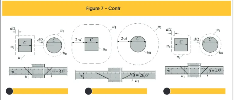
According to ACI 318 [7] the punching resistance of reinforced concrete lat slabs without shear reinforcement should be veriied by checking the shear stresses in a control perimeter d/2 away from the column faces or the ends of the loaded area, as shown in Figu -re 7a. The punching st-rength can be computed using Equation 1.
(
1)
!"#$%&'()*#
ol pe
ACI 318 NBR 6118 / EC2 T
A
B
C
where:
βc is the ratio between the largest and smaller side of the column; αs is a coeficient that is taken as 40 for internal columns, 30 for edge columns and 20 for corner columns;
u1 is the length of a control perimeter away d/2 from the column
face;
fc is the compressive strength of concrete in MPa (fc≤ 69 MPa); d is the effective depth of the slab.
4.2 NBR 6118
Recommendations presented by NBR 6118 [9] are based on those from CEB-FIPMC90 [6]. The Brazilian code recommends that the punching strength of slabs without shear reinforcement should be checked in both: a control perimeter u0 using Equation 2 to verify the maximum strength of the slab-column connection; and in a control perimeter u1 using Equation 3 to verify the diagonal tensile strength of the slab-column connection. Figure 7b presents details on the control perimeters of this code.
(5)
where:
(
)
1
1
250
v
f
cα = −
u0 is the control perimeter.
(
3)
where:
ρ is the lexural reinforcement ratio expressed by
ρ
=
ρ ρ
x⋅
y ;4.3 EUROCODE 2
EUROCODE 2 [8] also bases its recommendations to estimate the punching resistance of lat slabs in the recommendations of MC90. Thus, it recommendations are similar to the ones from NBR 6118. However, this code limits the value of the size effect on ξ ≤ 2.0 and also of the lexural reinforcement ratio ρ ≤ 2%, possibly trying to reduce the trends of unsafe results. Thus, punching strength is taken as the lowest value provided by Equations 4 and 5. Figure 7b shows the control perimeters of this code.
(
4)
(
where:
fc is the compressive strength of concrete in MPa (fc≤ 90 MPa); ρ is the lexural reinforcement ratio of the slab taken as
0,02
x y
ρ
=
ρ ρ
⋅
≤
;ρx and ρy are the lexural reinforcement ratios in or
-thogonal directions x and y, considering only bars wi -thin a region away 3∙d from the faces of column;
200
1
2,0
d
ξ = +
≤
;
u1 is the length of the control perimeter away 2∙d of the faces of column.
5. Critical Shear Crack Theory (CSCT)
The theory presented by Muttoni [3] is based on the idea that the punching resistance decreases with increasing rotation of the slab. This was explained by Muttoni and Schwartz [33] who observed that the shear strength decreases with the formation of a critical shear crack that propagates along the slab thickness, cutting the compression strut responsible for transmitting shear forces to the column in a mechanism as shown in Figure 8.
The authors use some experimental evidences to justify this ideali
-Figu
r � � � �
riti�a� �hear �ra�� theor�
(Muttoni [3])
+,-./01234/.54./678096:,;/;<=768>5;7.?@5;@@054,;@=6<40/5/65A,@-BC.44;@,6@D359E6/4FGHHIJ
C
r fer K LMNO PQRM PSKR TU PLSKV LRM W XMPLQM VKYO QK N R
d
zation of the behavior of the slab-column connection. They argue that, as shown in several experimental punching tests, the curva -ture in the radial direction is concentrated in the region close to the support, so that concentric cracks in the form of rings are only observed in this region. In the rest of the slab only radial cracks are observed (see Figure 9a). Since shear is not transferred in the tangential direction, the stress state is not affected by such cracks. In the region of the tangential cracks, part of the shear may be resisted by aggregate interlock on the surface of cracks and another part may be supported by dowel effect of the lexural reinforcement. As the tensile strength of concrete in the tensile diagonal is reached the tangential cracks (originally caused by bending of the slab) start to spread towards the column.
Also according to reports from several authors, including Ferreira [1], compressive strains in the radial direction nearby the ends of the column, after reaching a certain maximum value at a certain load level, start to decrease. Just before the punching failure it is possible to observe tensile strains in this area. This phenomenon can be explained by the formation of an elbow shaped strut (see Figure 9b) with a horizontal tensile member as a result of the ad -vance of the critical shear crack, cutting the compression zone. The opening of this crack reduces the resistance of the compres -sion strut because it affects the capacity of transferring shear for-ces by interlock aggregate and can eventually lead to a punching failure. Also according Muttoni and Schwartz [33] the thickness of this crack is proportional to the product ψ∙d (see Figure 8). Howe -ver, the transmission of shear in the critical crack is directly linked to its roughness, which in turn is a function of maximum aggregate size. Based on these concepts Muttoni [3] shows that the shear strength provided by the concrete can be estimated according to Equation 6.
(6)
where:
u1 is the length of a control perimeter d/2 away from the faces of the column (see Figure 7c);
fc is the compressive strength of concrete; ψ is the rotation of the slab;
dg0 is a reference diameter of the aggregate admitted as 16 mm; dg is the maximum diameter of the aggregate used in the concrete of the slab.
The rotationψof the slab is expressed by the Equation 7.
(
7)
where:
rs is the distance between the axis of the column and the line of
contralexure of moments;
rq is the distance between the axis of the column and the load line; rc is the radius of the circular column or the equivalent radius of a rectangular column;
fys is the yield stress of the tensile lexural reinforcement;
Es is the modulus of elasticity of the tensile lexural reinforcement; VE is the applied force;
2
s flex R q cr
V
m
r
r
π
= ⋅ ⋅
⋅
−
; 21
2
ys R ys cf
m
f
d
f
ρ
ρ
⋅
= ⋅
⋅
⋅ −
⋅
.With VE, ψ andVR,c is possible to draw a graph with two curves. The irst is a curve that expresses the theoretical load-rotation behavior of the slab. The second curve expresses the strength reduction of the slab due to the increase of rotation. The point of intersection of these two curves express the punching strength of a slab-column connection. Figure 10 illustrates this graph.
6. Evaluation of theoretical methods
Aiming to evaluate the accuracy of the theoretical methods presen -ted in the previous sections, results of tests on 74 lat slabs were taken together in a database. The main criterias for the formation of this database were the level of reliability of the results, trying to select results with great acceptance within the scientiic community, and the range of the database related to the parameters that inluen -ce the punching resistan-ce of lat slabs without shear reinfor-cement. Were used slabs tested by Elstner and Hognestad [2], Kinunnem and Nylander [14], Moe [15] Regan [20], Marzouk and Hussein [18], Tomaszewicz [34] and Hallgren [17]. Table 1 shows the characteris -tics of the slabs of the database. It should be emphasized that slabs in this database partially attend the limits of design codes. For exam -ple, NBR 6118 states that the smallest thickness for a lat slab must be 160 mm, which does not occur in all the slabs in the database. However, it is considered that scientiically it is important not to stick to these limits, since the interest is to understand the phenomenon as a whole and not just for the most common design situations.
Table � � Characteristics of slabs i� the database
Author
Slab
r
s(mm)
(mm)
r
q(mm)
h
(mm)
d
(mm)
C
(MPa)
f
c(MPa)
f
ys(GPa)
E
s,f(mm)
d
g(kN)
P
uA-1b
915
890
152
118
0.012
254
S
25.2
332
200
25
365
A-1c
915
890
152
118
0.012
254
S
29.0
332
200
25
356
A-1d
915
890
152
118
0.012
254
S
36.6
332
200
25
351
A-1e
915
890
152
118
0.012
254
S
20.3
332
200
25
356
A-2b
915
890
152
114
0.025
254
S
19.5
321
200
25
400
A-2c
915
890
152
114
0.025
254
S
37.4
321
200
25
467
A-7b
915
890
152
114
0.025
254
S
27.9
321
200
25
512
A-3b
915
890
152
114
0.037
254
S
22.6
321
200
25
445
A-3c
915
890
152
114
0.037
254
S
26.5
321
200
25
534
A-3d
915
890
152
114
0.037
254
S
34.5
321
200
25
547
A-4
915
890
152
118
0.012
356
S
26.1
332
200
25
400
A-5
915
890
152
114
0.025
356
S
27.8
321
200
25
534
B-9
915
890
152
114
0.020
254
S
43.9
341
200
38
505
B-14
915
890
152
114
0.030
254
S
50.5
325
200
38
578
IA15a/5
920
855
149
117
0.008
150
C
27.9
441
210
32
255
IA15a/6
920
855
151
118
0.008
150
C
25.8
454
210
32
275
IA30a/24
920
855
158
128
0.010
300
C
25.9
456
210
32
430
IA30a/25
920
855
154
124
0.011
300
C
24.6
451
210
32
408
S1-60
915
890
152
114
0.011
254
S
23.3
399
179
38
389
S1-70
915
890
152
114
0.011
254
S
24.5
483
171
38
393
S5-60
915
890
152
114
0.011
203
S
22.2
399
179
38
343
S5-70
915
890
152
114
0.011
203
S
23.0
483
171
38
378
H1
915
890
152
114
0.011
254
S
26.1
328
195
38
372
M1A
915
890
152
114
0.015
305
S
20.8
481
195
38
433
I/2
1,000 915
100
77
0.012
200
S
23.4
500
200
10
176
I/4
1,000 915
100
77
0.009
200
S
32.3
500
200
10
194
I/6
1,000 915
100
79
0.008
200
S
21.9
480
200
10
165
I/7
1,000 915
100
79
0.008
200
S
30.4
480
200
10
186
II/1
1,450 1,373 250
200
0.010
250
S
34.9
530
200
20
825
II/2
1,000 900
160
128
0.010
160
S
33.3
485
200
20
390
II/3
1,000 900
160
128
0.010
160
S
34.3
485
200
10
365
II/4
500
450
80
64
0.010
80 S
33.3
480
200
20
117
II/5
500
450
80
64
0.010
80 S
34.3
480
200
10
105
II/6
500
450
80
64
0.010
80 S
36.2
480
200
5
105
III/1
750
685
120
95
0.008
150
S
23.2
494
200
10
197
III/3
750
685
120
95
0.008
150
S
37.8
494
200
10
214
III/5
750
685
120
93
0.015
150
S
26.8
464
200
10
214
III/6
750
685
120
93
0.015
150
S
42.6
464
200
10
248
V/1
800
750
150
118
0.008
54 S
34.3
628
200
10
170
V/2
800
750
150
118
0.008
170
S
32.2
628
200
10
280
V/3
800
750
150
118
0.008
110
S
32.4
628
200
10
265
V/4
800
750
150
118
0.008
102
S
36.2
628
200
10
285
Elstner and
Hognestad [2]
Kinunnem and
Nylander [14]
Moe [15]
Some criteria were established in order to evaluate results ob -tained with the theoretical methods used in comparison with the experimental results. In general, it is expected that theoretical me -thods meet two basic principles: safety and precision. Primarily, it is desirable that, within a representative range of the design varia -bles of lat slabs or slabs with the loads applied in small areas, the methods are able to provide safety results, with a minimum of fra -gile results (unsafe). In this regard, it was established that no more than 5% of unsafe results would be ideal. The accuracy of obtained results was evaluated according to the average of the ratio Pu/Vcalc, were Pu is the experimental failure load and Vcalc is the theoretical resistance estimated by each method. For the average, it was esta -blished that: the method presents a high level of precision if 1.0 ≤
Pu/Vcalc <1.10; for to values of 1.10 ≤ Pu/Vcalc≤ 1.30 the method has a satisfactory level of precision; and for Pu/Vcalc > 1.30 the method is conservative. The coeficient of variation (COV) was also used to evaluate the precision of the methods, but without establishing ranges for the ideal values of the coeficient of variation, with these results used only in a qualitative way.
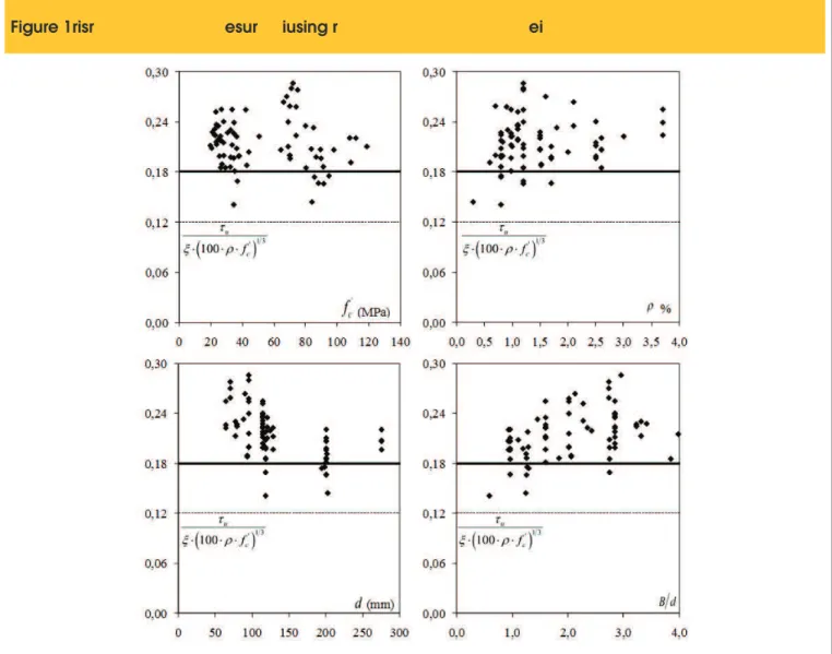
Figure 11 shows a comparison between the experimental results with theoretical results obtained with the recommendations of ACI 318 [7]. The solid line in the igures represents the level of the nominal strength and the dotted line represents the level of the de-sign strength. By varying the parameters fc (compressive strength of concrete) and B/d (equivalent diameter of the column u0/π divi-ded by the effective depth d of slab) it is observed that only 5% of Z
able � � Character�st�cs of slabs �� the database (co�t�)
Author
Slab
r
s(mm)
(mm)
r
q(mm)
h
(mm)
d
(mm)
C
(MPa)
f
c(MPa)
f
ys(GPa)
E
s,f(mm)
d
g(kN)
P
uHS2
850
750
120
95
0.007
150
S
70.0
490
200
20
249
HS3
850
750
120
95
0.012
150
S
69.0
490
200
20
356
HS4
850
750
120
90
0.021
150
S
66.0
490
200
20
418
HS7
850
750
120
95
0.009
150
S
74.0
490
200
20
356
HS8
850
750
150
120
0.010
150
S
69.0
490
200
20
436
HS9
850
750
150
120
0.015
150
S
74.0
490
200
20
543
HS10
850
750
150
120
0.021
150
S
80.0
490
200
20
645
HS11
850
750
90
70
0.007
150
S
70.0
490
200
20
196
HS12
850
750
90
70
0.012
150
S
75.0
490
200
20
258
HS13
850
750
90
70
0.016
150
S
68.0
490
200
20
267
HS14
850
750
120
95
0.012
220
S
72.0
490
200
20
498
HS15
850
750
120
95
0.012
300
S
71.0
490
200
20
560
NS1
850
750
120
95
0.012
150
S
42.0
490
200
20
320
65-1-1
1,500
1,250
320
275
0.015
200
S
64.3
500
200
16 2,050
65-2-1
1,300
1,100
240
200
0.017
150
S
70.2
500
200
16 1,200
95-1-1
1,500
1,250
320
275
0.015
200
S
83.7
500
200
16 2,250
95-1-3
1,500
1,250
320
275
0.025
200
S
89.9
500
200
16 2,400
95-2-1
1,300
1,100
240
200
0.017
150
S
88.2
500
200
16 1,100
95-2-1D
1,300
1,100
240
200
0.017
150
S
86.7
500
200
16 1,300
95-2-3
1,300
1,100
240
200
0.026
150
S
89.5
500
200
16 1,450
95-2-3D
1,300
1,100
240
200
0.026
150
S
80.3
500
200
16 1,250
95-2-3D+
1,300
1,100
240
200
0.026
150
S
98.0
500
200
16 1,450
95-3-1
750
550
120
88
0.018
100
S
85.1
500
200
16
330
115-1-1
1,500
1,250
320
275
0.015
200
S
112.0
500
200
16 2,450
115-2-1
1,300
1,100
240
200
0.017
150
S
119.0
500
200
16 1,400
115-2-3
1,300
1,100
240
200
0.026
150
S
108.1
500
200
16 1,550
HSC 1
1,270
1,200
245
200
0.008
250
C
91.3
627
200
18
1021
,
HSC 2
1,270
1,200
240
194
0.008
250
C
85.7
620
200
18
889
HSC 4
1,270
1,200
240
200
0.012
250
C
91.6
596
195
18 1,041
HSC 6
1,270
1,200
239
201
0.006
250
C
108.8
633
210
18
960
N/HSC 8
1,270
1,200
242
198
0.008
250
C
94.9
631
213
18
944
HSC 9
1,270
1,200
239
202
0.003
250
C
84.1
634
231
18
565
Marzouk and
Hussein [18]
Figure ��
C2omor�
ri
sms2mt2
r
e
s
u
fla2t
r
i
mo2d�l�h�a 2c
lu2luma 2
u
s
i
s
g r
e
Amoo sd�l
i
msa2mt2(o)2%1f2MP2
the results are against safety. One of these results, represented by point without illing in the graphs, is below of the design strength estimated by ACI. It refers to slab HSC 9 from Hallgren [17], in which a small lexural reinforcement ratio was used (0.3%) and, although not speciied by the author, is possibly a slab that failed by lexural.
Figure 12 and Figure 13 show comparisons of experimental re -sults with those obtained using recommendations of NBR 6118 and Eurocode 2, respectively. It is possible to perceive that Euro -code, which presents recommendations similar to NB1, but with limitations on the value of size effect (ξ ≤ 2.0) and of the lexural reinforcement ratio (ρ ≤ 2%) shows about 11% of unsafe results, but no results below the line of the design strength. However, NB1 presents average nominal strength close to the experimental re -sults, with no results below the design strength, but is far from me -eting the limit of only 5% of unsafe results. In Figure 14 are shown comparisons with results obtained according to CSCT. It may be noted that 11% of results are below the nominal strength, but no result is below the design strength. Figure 15 shows graphs with the tendency of the results of codes and CSCT compared with
experimental results of 74 slabs from the database. It can be seen that the dispersion of these results, when using the recommenda -tions of NBR 6118, is very small.
trend of unsafe results would be modifying the coeficient 0.18 in Equa -tion 3 to 0.16. This small change would increase the average to 1.14, same value as CSCT, it wouldn’t change the coeficient of variation, and what is really important, could reduce the percentage of unsafe results from 47.3% to 9.5%, leaving the results of this code similar to the CSCT.
7. Conclusions
Several aspects of the development of lat slabs and of the para -meters that inluence their punching resistance were discussed in this paper. Recommendations of ACI 318 [7], EUROCODE 2 [8] and NBR 6118 [9] were also presented as well as those from the Critical Shear Crack Theory , as presented by Muttoni [3], which is the basis of recommendations for punching presented in new ib Model Code [4.5]. To evaluate the safety and precision of these theoretical methods, a database was formed with experimental re -sults of tests in 74 lat slabs without shear reinforcement.
It was observed that, generally, ACI’s recommendations are meant to be safe, but underestimate the punching strength of lat slabs in about 37% for those in the database. This code also presented a high coeficient of variation (0.16) for this which is the simplest case the design of a slab --column connection. EC2 presented satisfactory and safety results, being registered average results for the ratio Pu/Vcalc of 1.19. This code also presented a coeficient of variation of 0.14, below of the American code due to the fact that it takes into account the inluence of parameters such as the lexural reinforcement ratio and size effect, while that the American code considers only the compressive strength of concrete.
The Critical Shear Crack Theory has been widely discussed by the scientiic community and some critics are noteworthy. The main one, as pointed out by Ferreira [1], is that according to a scientiic point of view, taking as a fundamental hypothesis that the failure mechanism by punching occurs with only rigid body rotations of the segment of slab outside the punching cone (delimited by critical crack) contradicts experimental evidence (in the region of failure occurs rotation and sli -ding) and can lead to inappropriate results, especially in the case of slabs with shear reinforcement (estimating higher forces in the outer perimeters, which in practice is not observed). From technical point of view, is a signiicantly more complex method for routine use in design ofices and, as noted, presents results similar to those from Eurocode.
Figure �
C2o2mor�a
ris
ot2of2
r
esu
lds2f
r
or2hadacas 2
u
i
dA2dAos 2
using r
e
(orr thad
i
ots2of2m)m%
[\]^_`abcde\fghci]_jk__i_le_fgd_ij\^\imjn_cf_jgo\^f_h p^jh
Author
(mm)
d
(%)
f
cq r s tu
P
uvw xyz xACI
EC2
NB1
{| {}A
~ .
{wA
~ .
{ wA
~ .
{ wA
~ .
{wElstner and Hognestad [2]
114�118
1.2 �3.7 20�50 1.42
0.19
1.17
0.11
0.94
0.07
1.02
0.08
Kinnunen and Nylander [14]
117�128
0.8 �1.1 25�28 1.52
0.05
1.19
0.05
1.05
0.06
1.06
0.04
Moe [15]
114 1.1�1.5 20�26 1.47
0.08
1.30
0.05
1.11
0.05
1.14
0.06
Regan [20]
64�200
0.8 �1.5 22�43 1.28
0.11
1.14
0.12
0.93
0.09
1.16
0.11
Marzouk and Hussein [18]
70�120
0.7�2.1 42�80 1.41
0.16
1.39
0.11
1.12
0.09
1.27
0.09
Tomaszewicz [34]
88�275
1.5�2.6 64�119
1.48
0.08
1.11
0.08
1.06
0.07
1.16
0.06
Hallgren [17]
194�202
0.3�1.2 84�109
1.00
0.19
0.94
0.09
0.94
0.08
1.06
0.07
A
~ .
1 .37
1.19
1.01
1.14
{w
0.
16
0.
14
0.
11
0.
11
r
.
0.64
0.78
0.68
0.88
It is noteworthy that in this paper it was used CSCT in its most accu -rate version and if it had been used the version adopted in the new ib code, results would be practically as conservative as those from ACI (see Ferreira [1]).
The Brazilian code presented average results near to the expe -rimental ones (average 1.01). By not limiting parameters such as lexural reinforcement ratio and size effect, how does Eu -rocode, NBR 6118 presented a coeficient of variation of 0.11, lower than other codes. However, for 47% of slabs the punching strength estimated according to these equations were unsafe. This indicates that it is extremely necessary to review its re -commendations in order to avoid this inadequate trend. It was showed also that a simple change in the equation of this code could change this trend of unsafe results, raising the average to 1.14, equal to of the CSCT, but reducing the percentage of unsafe results to only 9.5%.
8. Acknowledgements
The authors would like to acknowledge CNPq and CAPES for i -nancial support in all steps of this research.
Figure 1� � Trend of results according to the different theoretical methods presented
ACI 318
NBR 6118
Eurocode 2
TFCC
A
C
B
D
9. References
[01] FERREIRA, M. P. (2010). Punção em Lajes Lisas de Concreto Armado com Armaduras de Cisalhamento e Momentos Desbalanceados. Tese de Doutorado em Estruturas e Construção Civil, Publicação E.TD – 007 A/10 Departamento de Engenharia Civil e Ambiental, Universidade de Brasília, Brasília, DF, 275p.
[02] ELSTNER, R. C., e HOGNESTAD, E., Shearing Strength of Reinforced Concrete Slabs. Journal of the American Concrete Institute, Proceedings, V. 53, No. 1, Jul. 1956, pp. 29-58.
[03] MUTTONI, A., Punching Shear Strength of Reinforced Concrete Slabs without Transverse Reinforcement, ACI Structural Journal, V. 105, No. 4, July-Aug. 2008, pp. 440-450.
[04] ib Bulletin 55, Model Code 2010 – First complete draft, Volume 1,318p., 2010.
[06] Comité Euro-InternationalduBéton. CEB-FIP Model Code 1990. London, Thomas Telford, 1993.
[07] ACI Committee 318, Building Code Requirements for Structural Concrete (ACI 318-08) and Commentary, American Concrete Institute, Farmington Hills, Michigan, 2008.
[08] Eurocode 2, Design of Concrete Structures—Part 1-1: General Rules and Rules for Buildings, CEN,
EN 1992-1-1, Brussels, Belgium, 2004, 225 pp. [09] ASSOCIAÇÃO BRASILEIRA DE NORMAS TÉCNICAS.
NBR 6118 – Projeto de Estruturas de Concreto. Rio de Janeiro, 2007.
[10] GASPARINNI D. A., Contributions of C. A. P. Turner to development of reinforced concrete lat slabs 1905–1999. Journal of Structural Engineering, 2002, 128, No. 10, 1243–1252.
[11] FURST, A., MARTI, D., Robert Maillart’s design approach for lat slabs. Journal of Structural Engineering, 1997, No. 123(8), 1102–1110. [12] KIERDORF, A., Early Mushroom Slab Construction
in Switzerland, Russia and the U.S.A. - A Study in Parallel Technological Development, In: Proceedings of the Second International Congress on Construction History, vol II, pp 1793 – 1807. Cambridge
Construction History Society, Cambridge University, 2006.
[13] TALBOT, A. N., Reinforced Concrete Wall Footings and Column Footings. Engineering Experiment Station, University of Illinois, Urbana, Bulletin No. 67, Mar. 1913, 114p.
[14] KINNUNEN, S., NYLANDER, H., Punching of Concrete Slabs Without Shear Reinforcement. Transactions of the Royal Institute of Technology, No. 158, Stockholm, Sweden, 1960, 112 pp.
[15] MOE, J., Shearing Strength of Reinforced Concrete Slabs and Footings Under Concentrated Loads. Development Department Bulletin D47, Portland Cement Association, Skokie, Illinois, Apr. 1961, 129p. [16] GRAF, O.. Versuche über die Widerstandsfähigkeit
von Eisenbetonplatten unter konzentrierter Last nahe einem Aulager. DeutscherAusschuβ fürEisenbeton, Heft 73, Berlin, 1933, 16 pp.
[17] HALLGREN, M., Punching Shear Capacity of Reinforced High Strength Concrete Slabs.
PhD-Thesis, KTH Stockholm, TRITA-BKN. Bulletin No. 23, 1996, 150p.
[18] MARZOUK, H.; HUSSEIN, A., Experimental Investigation on the Behavior of High-Strength Concrete Slabs. ACI Structural Journal, V. 88, No. 6, Nov.-Dec. 1991, pp. 701-713.
[19] HAWKINS, N.M., CRISWELL, M.E., and ROLL, F., Shear Strength of Slabs Without Shear Reinforcement, ACI Publication, Shear in Reinforced Concrete, V. SP 42, No. 30, 1974, pp. 677-720.
[20] REGAN, P. E.,Symmetric Punching of Reinforced Concrete Slabs. Magazine of Concrete Research, V. 38, No. 136, Sep. 1986, pp 115-128.
[21] REGAN, P. E., Behavior of reinforced concrete lat slabs. Report 89, Construction Industry Research
and Information Association (CIRIA); London, Feb. 1981, p 89.
[22] LONG, A. E.,A Two-Phase Approach to the Prediction of Punching Strength of Slabs. Journal of the
American Concrete Institute, Proceedings, V. 72, No. 2, Fev. 1975, pp. 37-45.
[23] REGAN, P. E.; BRÆSTRUP, M. W.,Punching Shear in Reinforced Concrete. Comité Euro-International du Béton, Bulletin d›Information, No. 168, Jan. 1985, 232 pp.
[24] SHERIF, A. G.; DILGER, W. H.,Punching Failure of a Full Scale High Strength Concrete Flat Slab. International Workshop on Punching Shear Capacity of RC Slabs – Proceedings, TRITA-BKN Bulletin 57, Stockholm, Sweden, 2000, pp 235-243.
[25] VANDERBILT, M. D.,Shear Strength of Continuous Plates. Journal of Structural Division, Proceedings, ASCE, V. 98, No. ST5, May 1972, pp. 961-973. [26] HAWKINS, N.M., FALLSEN, H.B., and HINOJOSA,
R.C., Inluence of Column Rectangularity on the Behavior of Flat Plate Structures, ACI Publication, Cracking,Delection, and Ultimate Load of Concrete Slab Systems, V. SP-30, No. 6, 1971, pp. 127-146. [27] OLIVEIRA, D. R. C.; REGAN, P. E.; MELO, G. S.
S.,Punching Resistance of RC Slabs with Rectangular Columns. Magazine of Concrete Research, Vol. 56, No. 3, London, 2004, pp. 123-138.
[28] GRAF, O., Versuche über die Widerstandsfähigkeit von allseitig auliegenden dicken Eisenbetonplatten unter Einzellasten, Deutscher Ausschuß für Eisenbeton, Heft 88, Berlin, 1938, 22p.
[29] RICHART, F. E., Reinforced Concrete Wall and Column Footings. ACI Journal, Proceedings, V. 45, No. 10, Oct. 1948, pp. 97-127.
[30] BROMS, C. E., Shear Reinforcement for Delection Ductility of Flat Plates, ACI Structural Journal, V. 87, No. 6, Nov.-Dec. 1990, pp. 696-705.
[31] LI, K. K. L.,Inluence of Size on Punching Shear Strength of Concrete Slabs. M. Eng. Thesis, McGill University, Montreal, Québec, 2000, 78 pp.
[32] BIRKLE, G., Punching of Flat Slabs: The Inluence of Slab Thickness and Stud Layout. PhD Thesis. Department of Civil Engineering, University of Calgary, Calgary, Canadá, 2004, 152 pp.
[33] MUTTONI, A., and SCHWARTZ, J., Behavior of Beams and Punching in Slabs without Shear Reinforcement, IABSE Colloquium, V. 62, Zurich, Switzerland, 1991, pp. 703-708.
![Figure 1 � Punching shear failure in slabs without shear reinforcement (Ferreira [1])](https://thumb-eu.123doks.com/thumbv2/123dok_br/18859891.417744/2.892.59.834.827.1139/figure-punching-shear-failure-slabs-shear-reinforcement-ferreira.webp)
![Figure 3 � Tests on footings, basis for the first recommendations on punching shear (Talbot [13])](https://thumb-eu.123doks.com/thumbv2/123dok_br/18859891.417744/4.892.66.836.843.1135/figure-tests-footings-basis-recommendations-punching-shear-talbot.webp)
![Figure 11 shows a comparison between the experimental results with theoretical results obtained with the recommendations of ACI 318 [7]](https://thumb-eu.123doks.com/thumbv2/123dok_br/18859891.417744/11.892.84.825.215.900/figure-comparison-experimental-results-theoretical-results-obtained-recommendations.webp)