American Journal of Engineering Research (AJER)
e-ISSN: 2320-0847 p-ISSN : 2320-0936
Volume-6, Issue-1, pp-07-13
www.ajer.org
Research Paper Open Access
Flexural Behaviour of High Performance Reinforced Concrete
Beams Using Industrial Byproducts
A.Jayaranjini
1* and B.Vidivelli
21Research Scholar, Department of civil & Structural Engineering, Annamalai University, Chidambaram, Tamil
Nadu.
2Professor, Department of Civil & Structural Engineering, Annamalai University, Chidambaram, Tamil Nadu.
ABSTRACT:
In this study experimental investigations were carried out to explore the possibility of using Fly Ash, silica fume and metakaol in as a replacement of cement and bottom ash as a replacement of sand to make high performance concrete mixtures. The main objective of this study is to evaluate the flexural strength of high performance concrete beams by utilizing fly ash, silica fume, metakaolin and bottom ash. A total of eight rectangular beams were cast and tested. The beams were 125 mm 250 mm in cross-section and 3200 mm long. The beams were tested in two point loading over a simply supported span of 3000 mm. Of the above eight beams, 2 beams served as control specimen, 6 beams were cast with three different combinations of replacement of cement and fine aggregate. All the beams were evaluated in terms of load, deflection, moment, curvature and ductility. The test results indicated that beam with cement replacement by 10% silicafume and 10% metakaolin and fine aggregate replacement by 20% bottom ash exhibit 60% increase in load carrying capacity when compared to that of control beam.Keywords:
Bottom ash, fly ash, high performance concrete, metakaolin, silica fume.I.
INTRODUCTION
Worldwide, rapid industrialization increased the productivity of industrial wastes. The production of industrial byproducts like fly ash, bottom ash, silica fume and metakaolin has increased considerably. Feasibility of utilizing such industrial byproducts in enhancing the structural of high performance concrete is a challenging task. An expansion of material technology made it possible to design high performance concrete having superior mechanical properties and structural behaviour. In recent years high performance concrete become popular and is being used increasingly in reinforced concrete structures to avoid premature deterioration of concrete. The acceleration in use of high performance concrete is due to its enhanced mechanical properties like high density with high modulus of elasticity, impact resistance and high strength and better structural performance when compared to conventional concrete. The high performance concrete offers economy and superior performance in strength and long term behaviour. Most commonly used supplementary cementitious materials like silica fume (micro silica), fly ash, and blast furnace slag are commonly used in high performance concrete to activate their pozzolanic action which in turn exhibit increased strength, workability, durability, resistance to cracks and permeability of high performance concrete. American Concrete Institute (ACI) defines high performance concrete as a specially engineered concrete, one or more specific characteristics of which have been enhanced through the selection of component materials and mix proportions. To study the mechanical properties such as compressive strength, flexural strength and modulus of elasticity of concrete. This results shows that the maximum strength will be achieved. Totally 8 beams were cast for mixes CC, HPC1-HPC3. This paper determines flexural performance of the tested beams for example failure modes, load deflection response, Ductility Index, crack width under ultimate load were compared to that of control beams.
II.
LITERATURE REVIEW
compressive strength and the modulus of elasticity at early ages. However, the increase subsides at later ages (> 28 days). On the other hands, adding fly ash to HPC reduces both the compressive strength and the modulus of elasticity at early ages, but they increase at later ages. HPC containing combination of silica fume and fly ash behaves similar to HPC containing silica fume. Ganesan et al (2007) compared the behaviour of high performance concrete (HPC) and steel fibre reinforced high performance concrete (SFRHPC) flexural members under two point loading. HPC mix was designed to obtain a concrete grade of M60. In order to improve the flexural performance the steel fibres were added to HPC. A total number of ten flexural specimens of size 100 x 150 x1200 mm. using HPC and SFRHPC were cast and tested under static loading. Results indicated that introduction of steel fibres significantly improve the cracking behavior in terms of significant increase in first crack load and the formation of large number of finer cracks. Kumar et al (2007) studied the flexural behavior of high performance reinforced concrete beams made with crushed sandstone as coarse and fine aggregate together with silica fume. The beams were made from concrete having compressive strength of 74 and 78 N/mm2 and tensile reinforcement ratio in the range of 1.34 - 3.14%. Due to lower stiffness of sandstone aggregates, the beams resulted in excessive deflection under service loads. The experimented ultimate moment was found to be higher by about 14 - 30% and about 3 - 9% compared to the ultimate moment predicted based on BS and on ACI code, respectively. The crushed sandstone with silica fume improved the compressive strength and modulus of elasticity. Sandstone aggregates allows the stress to be more uniformly distributed in concrete and the beams exhibited higher flexural strength at ultimate load.
III.
EXPERIMENTAL PROGRAM
3.1 Materials Used
Ordinary Portland Cement, OPC 43 grade Confirming to IS 8112-1989 was used. Fine Aggregate, conforming to grading zone III of IS 383:1970. Its specific gravity and fineness modulus was 2.6 and 3.2. Coarse Aggregate of nominal size 20mm and Specific gravity 2.78 and fineness modulus 7.27 conforming to IS 383:1970 was used. Silica fume was obtained from M/s ELKEM Pvt.Ltd. Mumbai, named Elkem-micro silica 920 D was used. Fly ash (FA) obtained from Thermal power plant, Neyveli Lignite Corporation, Tamil nadu, India. Metakaolin is a mineral admixture obtained by refining the kaolin clay which further going to produce amorphous alumino silicate that is having good ability of reactiveness towards concrete. Metakaolin procured from the ASTRA Chemicals, chennai. Bottom ash is one of the Industrial byproduct and obtained from thermal power plant, Neyveli Lignite Corporation Ltd, at Neyveli, Tamilnadu, India. The Specific gravity and fineness modulus of bottom ash was 2.35 and 2.93 Conforming to IS 383:1970, Zone III. Chemical admixture CONPLAST SP 430 in the form of Sulphonated Naphthalene polymer complies with IS:9103-1999 were used to improve the workability of concrete.
3.2 Mix Proportions
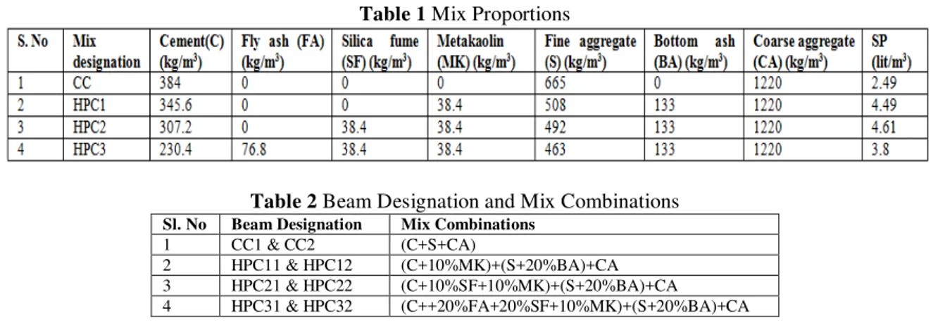
The mix proportions for conventional concrete and volume based partial replacement of Ordinary Portland cement (OPC) by Fly ash (FA), Silica fume (SF) and Metakaolin (MK) and also fine aggregate (sand) by Bottom ash is given in Table 1. Beam Designation and Mix Combinations are given in Table 2. The Conventional concrete used with mix proportion of 1:1.73:3.2 with w/c 0.45.
Table 1 Mix Proportions
Table 2 Beam Designation and Mix Combinations Sl. No Beam Designation Mix Combinations
1 CC1 & CC2 (C+S+CA)
2 HPC11 & HPC12 (C+10%MK)+(S+20%BA)+CA 3 HPC21 & HPC22 (C+10%SF+10%MK)+(S+20%BA)+CA 4 HPC31 & HPC32 (C++20%FA+20%SF+10%MK)+(S+20%BA)+CA
3.3 Beam Details
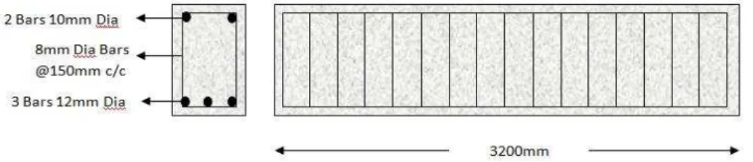
The reinforcing cage consisted of three 12mm diameter HYSD bars at the tension side, two 10 mm HYSD bars as hanger bars and 8 mm two legged stirrups at 150mm c/c. Longitudinal steel ratio adopted for the beam specimens was 1.23%. The detail of reinforcement is shown in Fig. 1.
3.4 Testing Procedure
The specimens were tested in a standard load testing frame of 500 kN capacity. All the beams were simply supported over a span of 3000 mm and tested under two point loading. Dial gauges capable of measuring to an accuracy of +_0.001mm were placed at mid span and at 1/3rd spans used for the measurement of deflections. The deflections were measured at a load increment of every 2.5 kN. Demec gauge were attached to the central region of the beams to measure the concrete compressive strain in pure bending region. Load at the first crack was also observed. The loading were continued until failure and all the measurements were taken at all stages of loading. The crack development were visually monitored and marked during the progress of the test. The crack widths were measured using a crack detection microscope of 0.02 mm. The schematic view of test setup is shown in Fig. 2 and Experimental Test setup for loading as shown in fig.3.
Fig. 2 Schematic View of Test Setup
IV.
RESULTS AND DISCUSSIONS
The measuring parameters considered for this research work included initial cracking and deflection, ultimate load and deflection, Crack width at every intervals of loading and mode of failure. The calculated parameters are service load and deflection, yield load and deflection, deflection ductility, deflection ductility ratio, energy ductility and energy ductility ratio.
Load - Deflection Behaviour
Load- deflection curves exhibits four regions of behaviour. At initial load concrete behaves in a linear elastic manner. As the load increases, the extreme fibre stresses in bending increase until the tensile strength of concrete is reached. This causes flexural cracking initially in the constant moment region. After the concrete cracks in the tension zone, a greater portion of the tensile component of the bending moment is carried by the steel reinforcement. All the beams showed typical flexural failure. Flexural cracks were found in the constant moment zone extend vertically upwards and got wide as the load is increased. The calculated parameters at various stages of loading for control beam and high Performance concrete beams (HPC) were given in Table 3. Load- deflection response of tested beams were shown in Fig. 4.
Table.3 Load and Deflection at various stages Beam
Designation
First Crack Stage Service Stage Yield Stage Ultimate Stage Load
((kN)
Deflection (mm)
Load (kN)
Deflection (mm)
Load (kN)
Deflection (mm)
Load (kN)
Deflection (mm) CC1 10 0.74 33.33 9.23 42.5 18.37 50 41.78 CC2 12.5 0.93 36.67 9.50 45 18.46 55 43.61 HPC11 17.5 1.14 48.33 11.52 65 23.98 72.5 60.36 HPC12 20 1.34 50.00 11.84 67.5 25.69 75 65.25 HPC21 17.5 1.27 53.33 12.06 70 27.45 80 72.56 HPC22 22.5 1.6 56.67 12.76 75 29.98 85 78.85 HPC31 12.5 1.12 45.00 11.25 57.5 21.85 67.5 53.24 HPC32 15 1.19 46.67 11.71 60 23.9 70 59.8
Fig.4 Load Deflection response of all Beams
for deflection at service load, 30.54% to 39.17%, 59.43% to 62.41% and 18.94% to 29.47% for deflection at yield load and 44.47% to 49.62%, 73.67% to 80.81% and 27.43% to 37.12% for deflection at ultimate load respectively with respect to CC. Overall the HPC mixes, HPC22 beam exhibit maximum an increase of first crack, service, yield and ultimate deflection which was found to be 72.04%, 34.32%, 62.41% and 80.81% respectively with respect to Control beam.
Moment Curvature Relationship
The results of ultimate moment and deflection curvature are mentioned in the Table 4 for all beams. Moment-Curvature Curves were calculated for all the beams based on the deflection as shown in figure 5. From the test results, moment can be observed that the HPC11&HPC12, HPC21&HPC22 and HPC31&HPC32 beams exhibit an increase in 36.36% to 45%, 54.54% to 60% and 27.27% to 35% for ultimate moment respectively with respect to Control beam (CC).
The Curvature can be observed that the HPC11&HPC12, HPC21&HPC22 and HPC31&HPC32 beams exhibit an increase in 44.47% to 49.87%, 73.85% to 81.13% and 27.49% to 37.46% respectively with respect to CC. Overall the HPC mixes, HPC22 beam exhibit maximum an increase of ultimate moment and curvature which was found to be 60% and 81.13% respectively with respect to CC.
Table.4 Moment Vs Curvature S. No Beam
Designation
Ultimate Load (kN)
Ultimate moment (kN.m)
Curvature x 10-5 (radian/mm)
1 CC1 50.0 25.00 3.71
2 CC2 55.0 27.50 3.87
3 HPC11 72.5 36.25 5.36
4 HPC12 75.0 37.50 5.80
5 HPC21 80.0 40.00 6.45
6 HPC22 85.0 42.50 7.01
7 HPC31 67.5 33.75 4.73
8 HPC32 70.0 35.00 5.32
Fig.5 Moment Curvature for all beams
Failure Modes and Cracking behavior of Tested Beams
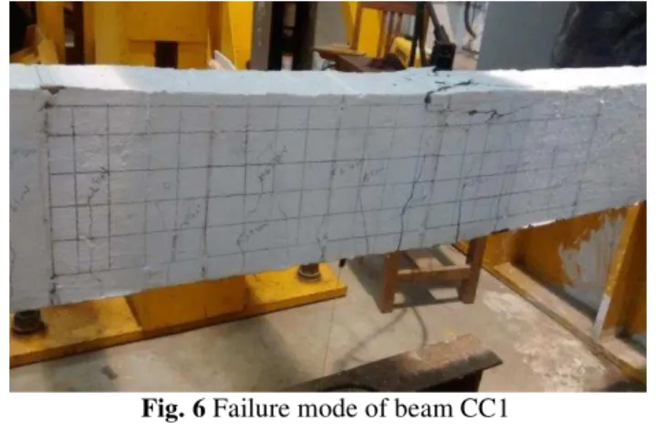
In this study all the beam specimens failed in flexure mode only. Sudden failure was not occurred in
high performance concrete beams. Failure mode of beam CC1 is shown in Fig. 6. It can inferred that the
reduction in crack width is directly related to partial replacement of cement and fine aggregate with silica fume, metakaolin and bottom ash. In all the beams flexural cracks were observed. These cracks were observed mostly in the constant moment region. Table 5 shows the measured crack width at every load interval at the tension steel level and the crack formation were marked on the beam. As observed all the beams exhibited vertical cracks known as flexural cracks in the pure bending region before failure. Normally the reinforcement ratios significantly control the crack width for flexural members. At ultimate stage the average crack width was 0.76 mm for beam HPC22 and 1.36 mm for control beam. HPC22 beam exhibit 44.11% lesser in crack width with
respect to control beam. All the experimental values of maximum crack width and crack spacing at the ultimate
Fig. 6 Failure mode of beam CC1
Table.5 Crack width for HPC beams
Deflection Ductility and Energy Ductility
Ductility of a beam is the ability to sustain inelastic deformation without any loss in its load carrying, prior to failure. Ductility can be expressed in terms of deformation or energy. The ductility values for the beams were calculated based on deflection and energy absorption. The deflection ductility values were calculated as the ratio between the deflections at ultimate load point to the deflection at yield load point. The energy ductility values were calculated as the ratio of the cumulative energy absorption at ultimate stage to the cumulative absorption at yield stage. The ductility values of tested beams were presented in Table 6 and Figure 7. From the test results, Deflection ductility and energy ductility can be observed that the HPC11&HPC12, HPC21&HPC22 and HPC31&HPC32 beams exhibit an increase in 7.5% to 10.67%, 11.33% to 16.22% and 5.91% to 7.31% and also 12.92% to 13.30%, 19.68% to 22.44% and 9.90% to 11.47% respectively with respect to CC.
Table 6. Ductility Values of Tested Beams S. No Beam
Designation
Deflection Ductility
Deflection Ductility Ratio
Energy Ductility
Energy Ductility Ratio
1 CC1 2.27 1.00 15.24 1.00
2 CC2 2.36 1.00 15.86 1.00
3 HPC11 2.52 1.11 17.21 1.13
4 HPC12 2.54 1.08 17.97 1.13
5 HPC21 2.64 1.11 18.24 1.20
6 HPC22 2.63 1.16 19.42 1.22
7 HPC31 2.44 1.07 16.75 1.10
8 HPC32 2.50 1.06 17.68 1.11
Figure 7. Ductility Ratio of Tested Beams
S. No Beam Designation
Average Crack Width at ultimate load (mm)
No of Cracks between loading points
1 CC1 1.22 17
2 CC2 1.36 15
3 HPC11 1.07 14
4 HPC12 1.04 13
5 HPC21 0.94 10
6 HPC22 0.76 10
7 HPC31 1.14 12
V.
CONCLUSIONS
The following conclusions were drawn from the experimental study conducted on various combinations of mixes in high performance concrete. All beams exhibit the failure under flexure mode only.HPC beams with Industrial Byproducts shows improved the load carrying capacity, ductility and reduction in crack width during the ultimate stage.
From the test results, load can be observed that the HPC11&HPC12, HPC21&HPC22 and HPC31&HPC32 beams exhibit an increase in 60% to 75%, 75% to 80% and 20% to 25% for first crack load, 36.35% to 45%, 54.54% to 60.01% and 22.72% to 35.01% for service load, 50% to 52.94%, 64.71% to 66.67% and 33.33% to 35.29% for yield load and 36.36% to 45%, 54.55% to 60% and 27.72% to 35% for ultimate load respectively with respect to Control beam(CC).
The deflection can be observed that the HPC11&HPC12, HPC21&HPC22 and HPC31&HPC32 beams exhibit an increase in 44.09% to 54.05%, 71.62% to 72.04% and 20.43 to 27.95% for deflection at first crack load, 24.63% to 24.81%, 30.66% to 34.32% and 21.89% to 23.26% for deflection at service load, 30.54% to 39.17%, 59.43% to 62.41% and 18.94% to 29.47% for deflection at yield load and 44.47% to 49.62%, 73.67% to 80.81% and 27.43% to 37.12% for deflection at ultimate load respectively with respect to CC.
From the test results, moment can be observed that the HPC11&HPC12, HPC21&HPC22 and HPC31&HPC32 beams exhibit an increase in 36.36% to 45%, 54.54% to 60% and 27.27% to 35% for ultimate moment respectively with respect to Control beam (CC).
The Curvature can be observed that the HPC11&HPC12, HPC21&HPC22 and HPC31&HPC32 beams exhibit an increase in 44.47% to 49.87%, 73.85% to 81.13% and 27.49% to 37.46% respectively with respect to CC.
From the test results, Deflection ductility can be observed that the HPC11&HPC12, HPC21&HPC22 and HPC31&HPC32 beams exhibit an increase in 7.5% to 10.67%, 11.33% to 16.22% and 5.91% to 7.31% respectively with respect to CC.
From the test results, energy ductility can be observed that the HPC11&HPC12, HPC21&HPC22 and HPC31&HPC32 beams exhibit an increase in and also 12.92% to 13.30%, 19.68% to 22.44% and 9.90% to 11.47% respectively with respect to CC.
In all stages, HPC22 beam exhibit maximum an increase of load, deflection, ultimate moment, curvature,
deflection ductility and energy ductility is 60%, 80.81%, 60%, 81.13%, 16.22 and 22.44% and also 44.11% lesser in crack width respectively with respect to CC.
REFERENCES
[1]. Delsye C. L. Teo, Md. Abdul Mannan and John V. Kurian, (2007), “Flexural behaviour of reinforced lightweight concrete beams
made with oil palm shell (OPS)”, Journal of advanced concrete technology .vol (4), 3: 459-468.
[2]. Ganesan, N., Indira, P.V. and Abraham, R., (2007), “Behaviour of steel fibre reinforcement high performance concrete member
under flexure”, IE (I) Journal- CV, Vol. 88, pp. 20-23.
[3]. IS 456:2000, Code of practice for plain and Reinforced concrete, (Bureau of Indian Standards), New Delhi. [4]. IS 8112:1989, Indian standard Ordinary Portland Cement, 43grade - Specifications.
[5]. IS 383:1970, Specifications for Coarse and Fine Aggregates from Natural Sources for Concrete. Bureau of Indian Standards, New Delhi.
[6]. IS 9103:1999 Indian Standard concrete Admixtures – specification.
[7]. IS 516:1959 Methods of test for strength of concrete, (Bureau of Indian Standards), New Delhi.
[8]. Jian – Tong Ding and Zongjin Li, (2002), “Effects of Metakaolin and silica fume on properties of concrete”, Material Journal, Vol. 99, pp. 393-398.
[9]. Kumar, P.S., Mannan, M.A., Kurian, V.J and Achuytha, H.(2007) “Investigation on the flexural behaviour of high performance reinforced concrete beams using sandstone aggregates”, Bulding and Environment, Elsevier Ltd, Vol. 42, pp. 2622-2629.
[10]. Nakin Suksawang, Hani, H. Nassif and Padit Tanchan, (2006)”Comparison of Elastic Modulus Equations for High Performance Concrete (HPC) with Pozzolanic Materials, International Conference on Pozzolan, Concrete and Geopolymer”, Thailand, pp. 237 -246.
[11]. Prabhar R. Prem, A. Ramachandra Murthy, G. Ramesh, B. H. Bharatkumar & Nagesh R. Iyer, (2015),”Flexural behavior of damaged RC beams strengthened with ultra high performance concrete” Journal of Structural Engineering, vol.1, pp. 60-68. [12]. Park, R, Paulay, T. (1975), “Reinforced concrete structures”, John Wiley & Sons, Inc., New York.
[13]. Shanmugapriya, T. and Uma, R.N., (2013). “Experimental Investigation on Silica Fume as partial Replacement of Cement in High
Performance Concrete”, The International Journal of Engineering and Science (IJES), 2(5), pp.40-45.