Research Article
Low-Bit Rate Feedback Strategies for Iterative
IA-Precoded MIMO-OFDM-Based Systems
Sara Teodoro,
1Adão Silva,
1Rui Dinis,
2and Atílio Gameiro
11DETI, Instituto de Telecomunicac¸˜oes, Universidade de Aveiro, Campus Universit´ario de Santiago, 3810-193 Aveiro, Portugal 2Instituto de Telecomunicac¸˜oes, Faculdade de Ciˆencias e Tecnologia, Universidade Nova de Lisboa, 2829-516 Caparica, Portugal
Correspondence should be addressed to Sara Teodoro; steodoro@av.it.pt Received 7 October 2013; Accepted 21 November 2013; Published 11 February 2014 Academic Editors: A. Kaloxylos and S. Yatawatta
Copyright © 2014 Sara Teodoro et al. This is an open access article distributed under the Creative Commons Attribution License, which permits unrestricted use, distribution, and reproduction in any medium, provided the original work is properly cited. Interference alignment (IA) is a promising technique that allows high-capacity gains in interference channels, but which requires the knowledge of the channel state information (CSI) for all the system links. We design low-complexity and low-bit rate feedback strategies where a quantized version of some CSI parameters is fed back from the user terminal (UT) to the base station (BS), which shares it with the other BSs through a limited-capacity backhaul network. This information is then used by BSs to perform the overall IA design. With the proposed strategies, we only need to send part of the CSI information, and this can even be sent only once for a set of data blocks transmitted over time-varying channels. These strategies are applied to iterative MMSE-based IA techniques for the downlink of broadband wireless OFDM systems with limited feedback. A new robust iterative IA technique, where channel quantization errors are taken into account in IA design, is also proposed and evaluated. With our proposed strategies, we need a small number of quantization bits to transmit and share the CSI, when comparing with the techniques used in previous works, while allowing performance close to the one obtained with perfect channel knowledge.
1. Introduction
Coordination between cells is one of the fastest growing topics of research in wireless communications, and it is a promising solution for cellular wireless systems to mitigate intercell interference and provide the increased capacity expected in the forthcoming years [1, 2]. This technology is already under study in long-term evolution advanced (LTE A) under the coordinated multipoint concept (CoMP) [3]. Since the performance of cell-edge users is greatly limited by the intercell interference, the design of an efficient interference management scheme is crucial to improve the performance of those users.
One interesting recent scheme to efficiently eliminate the intercell interference and achieve a linear capacity scaling (i.e., the sum rates increase linearly with the number of users at high SNR) is interference alignment (IA) [4]. IA was firstly introduced for MIMO X channel in [4] and subsequently in the context of the 𝐾-user interference channel in [5]. With this technique, the transmitters align in the unwanted users’ receive signals in a subspace orthogonal to the subspace
used for that users’ data, through the use of appropriate precoders and thus allowing to achieve the maximum degrees of freedom (DoF). It was shown in [5] that the capacity of an interference channel (IC) is for a given user one-half the rate of its interference-free capacity in the high transmit power regime, regardless of the number of users.
A closed-form solution for constant channels is still unknown for more than 3 users. An explicit formulation of the precoding vectors achieving IA for time or frequency selectivity channels was presented in [5]. A two-stage opti-mization of the precoding and decoding matrices in the 𝐾-multi-input, multioutput (MIMO) constant interference channels was proposed in [6]. Some iterative algorithms were also proposed for these multiuser MIMO systems [7–
9]. In [7], the Max-SINR algorithm was proposed, where instead of minimizing interference power at each iteration, the algorithm iteratively maximizes the per-stream signal interference-plus noise ratio (SINR). A minimum mean squared error- (MMSE-) based iterative IA scheme has been proposed in [8], by relaxing the need for perfect alignment Volume 2014, Article ID 619454, 11 pages
while minimizing the signal’s sum mean square error. A com-parison between several iterative linear precoding designs using alternating minimization was performed in [9].
The knowledge of CSI at the transmitter is absolutely crucial for the precoder-based systems. When perfect channel state information (CSI) is available, IA achieves the optimum theoretical bound of DoF for interference channels [4]. However, assuming perfect CSI at the transmitters is not realistic in most of the scenarios, and the requirement of accurate CSI knowledge in all the cooperating nodes incurs in a large overhead penalty. Some works present the IA technique to improve a user communication in a cell-edge scenario for cellular networks using a leakage-based strategy, where only the interference from the stronger base station (BS) is cancelled. This decreases the CSI overhead since it only needs to perfectly know the CSI of one interferer, though this approach may not be realistic for some scenarios, where more than one relevant interferer does exist [10,11].
Some studies addressed the issue of CSI knowledge in the IA context through channel reciprocity, as in [12], where several iterative algorithms take advantage of the reciprocity of wireless networks to achieve IA. In such cases, IA precoders are generated through an iterative procedure consisted in sending pilots from the transmitters and estimating inter-ference covariance matrices at the receivers [12]. However, this method relies on pilots transmissions, which incurs in a nonnegligible overhead. Also this method cannot be used in frequency-division duplexed- (FDD-) based systems and requires tight synchronization in time-duplexed systems [13,14].
Another strategy to solve the CSI knowledge at the transmitters is to feed back the channels from user terminals (UTs) to the BSs [15–17]. Limited feedback, where the CSI is quantized and fed back to the transmitter through a limited link, was first introduced in [18], to single antenna systems using efficient quantization via what is known as Grassmannian codebooks. Nevertheless, the complexity of quantized feedback increases with codebook size and large Grassmannian codebooks are difficult to design and encode. Moreover, it cannot be applied to the systems where the CSI exhibits no special structure, as the main case of interest of IA in multiple antenna systems, where the CSI to be fed back is a set of channel matrices [13]. In [15], the theoretical boundary of DoF achieved with a limited feedback for MIMO multi-user systems is derived and an appropriate scheme is proposed. Random vector quantization (RVQ) codebooks are used in these cases because the optimal vector quantizer for this problem is not known in general [16,17]. Although RVQ techniques allow efficient IA schemes with limited feedback, the required codebooks can be very large, especially when we have a high number of transmit and receive antennas. Moreover, while RVQ performs well when there are a large number of mobiles relative to the number of transmit antennas, it performs poorly in the small system regime [19]. As a solution to this problem, quantization codebook size must scale exponentially with SNR, having however the drawback of becoming extensively large for high SNR. The encoding and decoding complexity can be very high, even for flat fading channels, becoming prohibitively
high for severely time-dispersive channels. In that case, it is preferable to employ simpler quantizers, working on a sample-by-sample basis, as in [20].
To overcome the problem of scaling complexity (code-books and computation complexity to quantize the CSI increases with the number of users and antennas), IA with analog feedback was considered in [14], where the channel coefficients are directly transmitted as uncoded quadrature and amplitude modulated symbols. However, analog feed-back does not warrant an accurate CSI and consequently a full multiplexing gain, if the forward and reverse link SNRs do not scale together (i.e., both SNRs increase together, so that when the SNR on the reverse link is high we also have high-quality CSI). Thus, the development of new feedback strategies with reduced overhead applicable with no channel restrictions is crucial to achieve the maximum DoF.
In this paper, we design new quantization strategies that allow efficient CSI feedback for IA-precoder MIMO-OFDM-based systems. A quantized version of the CSI associated with the different links between BS and UT is fed back from the UT to the BS and sent to the other BSs through a limited-capacity backhaul network. The proposed quantization strategies have low-complexity and low-bit rates just quantizing part of the samples of either the channel frequency response (CFR) or the channel impulse response (CIR). These quantized channels are then employed by the different BSs to perform the overall IA design. Our channel quantization methods have much lower complexity than the RVQ-based techniques, since they do not require the use of large codebooks. More-over, for severely time-dispersive channels, the RVQ-based schemes require the quantization of all subchannel samples; thus, the proposed scheme is even more advantageous for these cases, with lower feedback overhead. As the iterative IA MMSE-based algorithms have some degradation in high SNR due to channel errors, a new robust iterative IA technique is also proposed and evaluated using the proposed feedback strategies, where channel quantization errors are taken into account in IA design.
The remainder of the paper is organized as follows.
Section 2presents the system model of the𝐾-user IC MIMO for OFDM systems. The proposed channel feedback strate-gies are presented in Section 3. Section 4 briefly describes the proposed IA algorithms to be evaluated with limited feedback.Section 5presents the main simulation results. The conclusions and future work are drawn inSection 6.
Notation. Boldface capital letters denote matrices; boldface
lowercase letters denote column vectors. The operation(⋅)𝐻 represents the Hermitian transpose of a matrix; Re(⋅) and Im(⋅) represent the real and imaginary parts of a complex number, respectively; and arg(⋅) representes the phase of a complex number. E[⋅] stands for the expectation; ‖ ⋅ ‖ represents the Frobenius norm of a matrix;𝜄 is the imaginary unit; and, tr(⋅) refers to the trace of a square matrix.
2. System Characterization
In this paper, we consider the downlink of a multicell MIMO-OFDM-based system. Due to the orthogonality between
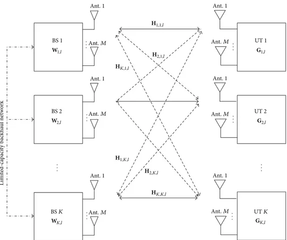
BS 1 BS 2 BS K UT 1 UT 2 UT K L imi te d-ca paci ty bac kha ul netw or k W1,l W2,l WK,l Ant. 1 Ant. 1 Ant. 1 Ant. 1 Ant. 1 Ant. 1 Ant. M Ant. M Ant. M Ant. M Ant. M Ant. M .. . .. . .. . .. . .. . .. . .. . .. . HK,1,l H1,1,l H1,K,l H2,1,l H2,K,l HK,K,l G1,l G2,l GK,l
Figure 1: A generic block diagram of the considered scenario.
subcarriers, we can apply IA independently for each OFDM subcarrier. Therefore, we have a𝐾-user MIMO interference channel with constant coefficients on a per-subcarrier basis. It comprises a𝐾 transmitter-receiver pair sharing the physical channel, with a given transmitter intending to have its signal decoded only by a single receiver. In a downlink-cellular-based system, the transmitter and receiver correspond to the BS and UT, respectively. We assume that the BSs are grouped in sets of 𝐾 elements that are linked through a limited-capacity backhaul network and the quantized version of the CSI associated with the different links between each BS and each UT is shared to all BSs, as shown inFigure 1. Without loss of generality, we consider a symmetric case where all BSs and UTs have𝑀 antennas, with 𝑀 even, which is denoted by an(𝑀, 𝑀, 𝐾) interference channel, with 𝑑𝑘 = 𝑑, for all 𝑘 streams per user. The results of this paper can be generalized to a network with different number of antennas as long as IA remains feasible [21]. Since each BS is allowed to transmit𝑑 = 𝑀/2 data symbols on each subcarrier, this system has 𝐾𝑀/2 DoF per subcarrier. Note that, with IA strategy, the capacity for any user is half the rate of its interference-free capacity [21]. An OFDM modulation with𝑁 available subcarriers is employed at each BS and linear precoding is done separately by each of the𝑁 subcarriers.
Under linear precoding, the received frequency-domain signal (i.e., after cyclic prefix removal and discrete Fourier
transform (DFT) operation) at the𝑘th UT and the 𝑙th sub-carrier(𝑙 = 0, . . . , 𝑁 − 1) is given by
y𝑘,𝑙= H𝑘,𝑘,𝑙W𝑘,𝑙s𝑘,𝑙+∑𝐾 𝑗=1 𝑗 ̸= 𝑘
H𝑘,𝑗,𝑙W𝑗,𝑙s𝑗,𝑙+ n𝑘,𝑙, (1)
provided that the cyclic prefix is long enough to account for different overall CIRs between the BSs and the UTs (i.e., including transmit and receive filters, multipath propagation effects, and differences in the time-of-arrival for different BS-to-UT links). s𝑘,𝑙 is the data symbols vector of size𝑀/2 × 1, with E[s𝑘,𝑙s𝐻
𝑘,𝑙] = I𝑀/2; W𝑗,𝑙 ∈ C𝑀𝑥𝑀/2 is the linear precoding matrix computed at BS𝑗 on subcarrier 𝑙, normal-ized such that‖W𝑗,𝑙‖2𝐹 = 𝑃𝑡 and 𝑃𝑡 is the transmit power at the BSs; and H𝑘,𝑗,𝑙 = √𝜌𝑘,𝑗H(𝑖𝑖𝑑)𝑘,𝑗,𝑙 is a size-𝑀 × 𝑀 matrix with the overall channel between the 𝑗th BS and the 𝑘th UT on the 𝑙th subcarrier. H(𝑖𝑖𝑑)𝑘,𝑗,𝑙 contains the fast fading coefficients with i.i.d.CN(0, 1) entries (independent, identically distributed complex normal random variables) and 𝜌𝑘,𝑗 = 2𝜎2𝑘,𝑗 represents the long term channel power on the same link. n𝑘,𝑙 is the additive white Gaussian noise (AWGN) vector at UT𝑘 on subcarrier 𝑙, that is, n𝑘,𝑙 ∼ CN(0, 𝜎𝑛2I𝑀).
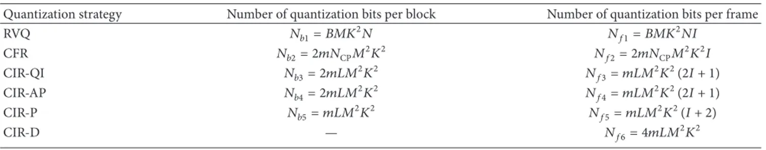
Table 1: Number of quantization bits required for the discussed quantization strategies for one OFDM block and for one frame (set of𝐼 blocks and a training sequence).
Quantization strategy Number of quantization bits per block Number of quantization bits per frame
RVQ 𝑁𝑏1= 𝐵𝑀𝐾2𝑁 𝑁𝑓1= 𝐵𝑀𝐾2𝑁𝐼 CFR 𝑁𝑏2= 2𝑚𝑁CP𝑀2𝐾2 𝑁𝑓2= 2𝑚𝑁CP𝑀2𝐾2𝐼 CIR-QI 𝑁𝑏3= 2𝑚𝐿𝑀2𝐾2 𝑁𝑓3= 𝑚𝐿𝑀2𝐾2(2𝐼 + 1) CIR-AP 𝑁𝑏4= 2𝑚𝐿𝑀2𝐾2 𝑁𝑓4= 𝑚𝐿𝑀2𝐾2(2𝐼 + 1) CIR-P 𝑁𝑏5= 𝑚𝐿𝑀2𝐾2 𝑁𝑓5= 𝑚𝐿𝑀2𝐾2(𝐼 + 2) CIR-D — 𝑁𝑓6= 4𝑚𝐿𝑀2𝐾2
The soft estimated symbols associated with the user𝑘 on subcarrier𝑙 are given by
̂s𝑘,𝑙= G𝑘,𝑙H𝑘,𝑘,𝑙W𝑘,𝑙s𝑘,𝑙
+ ∑𝐾 𝑗=1 𝑗 ̸= 𝑘
H𝑘,𝑗,𝑙W𝑗,𝑙s𝑗,𝑙+ G𝑘,𝑙n𝑘,𝑙, (2)
where G𝑘,𝑙denotes the linear receiving filter employed at the UT𝑘 on subcarrier 𝑙, with dimension of 𝑀/2 × 𝑀.
3. Channel Quantization Strategies
3.1. RVQ Strategy. We briefly describe the RVQ CSI feedback
quantization technique often considered for IA-based sys-tems, which is used here for comparison purposes [19,22]. For the sake of simplicity, we will drop the dependence on both transmit and receive antenna indexes. Thus, the CFR, between a given transmit-receive antenna link, is denoted by h = [ℎ0 ℎ1 ⋅ ⋅ ⋅ ℎ𝑁−1]𝑇. The constructed codebook for channel direction information (CDI), defined as the normalized CSI (i.e., h𝑑𝑘 = h𝑘/|h𝑘|), is formed by 2𝐵vectors i.i.d. on the𝑀-dimensional unit sphere, {c𝑏}, 𝑏 = 1, . . . , 2𝐵, where𝐵 represents the number of feedback bits. Each user quantizes its CDI to a codeword in a given codebook C𝑘 ∈ C𝑀×2𝐵
and the codebook is predetermined and known at both the BSs and user sides. Partial CSI is acquired at the transmitter via a finite-rate feedback channel from each of the receivers. Furthermore, we use the minimum Euclidean distance to choose the codeword closest to each channel vector direction; that is,
𝐹𝑖,𝑗,𝑚= arg min 𝑏=1,...,2𝐵1h 𝑑 𝑖,𝑗,𝑚− c𝑏 2 , (3)
with 𝑖, 𝑗 = 1, . . . , 𝐾, 𝑚 = 1, . . . , 𝑀. Thus, after the UT having sent the index of the codeword to the BS, it provides the channel used to design the precoder matrices, given by
h𝑄𝑖,𝑗,𝑚 = c𝐹𝑖,𝑗,𝑚 [16]. The number of quantization bits for the OFDM system is given by𝐵𝑀𝐾2𝑁.
3.2. Proposed Sample-by-Sample Strategies. In this subsection
we describe the proposed efficient channel quantization procedures, where a quantized version of the CSI associated with the different links between BSs and UTs is fed back from
the UT to the BS, which sends it to the other BSs through a limited-capacity backhaul network. This information is then used by each BS to perform the overall IA design. We consider that CIR is represented by ̃h(Δ𝑇𝑖) for OFDM symbol 𝑖, with Δ𝑇𝑖 = 𝑖𝑇𝑠, 𝑖 ∈ N, or in a simplified form by ̃h = [̃ℎ0 ̃ℎ1 ⋅ ⋅ ⋅ ̃ℎ𝑁−1]𝑇= F−1h, where F denotes an appropriate
DFT matrix, with each component given by ̃ℎ𝑙(Δ𝑇𝑖) = ̃ℎ𝐵𝐵(𝑙Δ𝑡𝑠+ Δ𝑇𝑖), for 𝑙 = 1, . . . , 𝑁 − 1; Δ𝑡𝑠 = 𝑇𝑠/𝑁, 𝑇𝑠is the duration of the OFDM block, ̃ℎ𝐵𝐵(𝑡) = ∑𝐿−1𝑗=0𝛽𝑗𝛿(𝑡− 𝜏𝑗) is the complex baseband representation of the CIR,𝐿 is the number of paths,𝛽𝑗is the complex amplitude of the𝑗th path, and 𝜏𝑗 is the delay of the𝑗th path. Of these 𝑁 CIR components, just 𝐿 are non-zero. Let us define Ψ as the group with the position of the nonzero CIR components in ̃h of size 𝐿.
The CFR is estimated at the receiver through appropriate training sequences and/or pilots. Assuming severely time-dispersive channels, the RVQ-based schemes require the quantization of𝑁 samples. To reduce it, we propose a new method which only requires part of CFR. In order to further reduce the overhead for CSI quantization, some new strate-gies are proposed based on part of CIR quantization, which are next described in detail: CIR-quadrature and in-phase (CIR-QI), CIR-amplitude and phase (CIR-AP), CIR-phase (CIR-P), and CIR-Doppler (CIR-D) quantization strategies.
Table 1presents the number of quantization bits required for each of the quantization strategies for a single OFDM block and for a set of𝐼 blocks, including the training sequence.
3.2.1. CFR Quantization. We propose a new method which
only requires the quantization of part of CFR. The CIR has a duration (notice that the referred duration is measured in terms of number of samples) that must be smaller than the duration of the cyclic prefix, 𝑁CP, which for typical OFDM implementations is much lower than𝑁. Therefore, we have ̃ℎ𝑛 = 0 for 𝑛 > 𝑁CP; that is, only the first 𝑁CP samples of the CIR are non-zero (it should be pointed out that the samples ̃ℎ𝑛are not necessarily associated to a given multipath component when the multipath components are not symbol-spaced). Therefore, when𝑁 ≥ 𝑁CPit is enough to sample the CFR at a rate𝑁/𝑁CP; that is, we only need𝑁CP equally spaced samples of the CFR to obtain it without loss of information [23]. Thus, we only need to quantize𝑁CPequally spaced samples of h (i.e., we quantize the samplesℎ𝑙 with
quantize and send the first𝑁CP samples of ̃h. We consider the separate quantization of the real and imaginary parts of each of the appropriate𝑁CPsamples of h, leading to
ℎ𝑄𝑙 = 𝑓𝑄(Re {ℎ𝑙}) + 𝜄𝑓𝑄(Im {ℎ𝑙}) , (4)
where 𝑓𝑄(⋅) denotes the quantization characteristic. This means that we only need2𝑚𝑁CP ≪ 2𝑚𝑁 bits to send the channel information from the UTs to the BSs (and this must be done for each link between transmit and receive antenna; that is, the number of bits is2𝑚𝑁CP𝑀2𝐾2).
3.2.2. CIR-QI Quantization. In order to optimize the number
of bits needed to quantize the CSI and since there are only𝐿 (with𝐿 ≪ 𝑁CPand𝑁CP≪ 𝑁) non-zero components in CIR, we can just quantize these𝐿 components (the delays and their complex amplitude). The delays just need to be transmitted once, since they are usually constant for over a large number of data blocks. Therefore, we quantize ̃ℎ𝑝(Δ𝑇𝑖) = 𝛽𝑝(Δ𝑇𝑖), with𝑝 ∈ Ψ, and 𝛽𝑝(Δ𝑇𝑖) ∈ C, which corresponds to the 𝑝th non-zero component of the𝑖th OFDM block. We consider the separate quantization of the real and imaginary parts of each component of ̃h(Δ𝑇𝑖), leading to
̃ℎ𝑄
𝑝(Δ𝑇𝑖) = 𝑓𝑄(Re {̃ℎ𝑝(Δ𝑇𝑖)}) + 𝜄𝑓𝑄(Im {̃ℎ𝑝(Δ𝑇𝑖)}) . (5) The number of quantization bits required is only2𝑚𝐿𝑀2𝐾2 per OFDM block, with 𝑚 denoting the number of bits required for the real and imaginary parts of each quantized component, which is much lower than in the case of CFR quantization strategy.
3.2.3. CIR-AP Quantization. Another quantization strategy
is based on the previous one, consisting in quantizing the amplitude and phase of the non-zero components of CIR, separately, so that
̃ℎ𝑄
𝑝(Δ𝑇𝑖) = 𝑓𝑄(̃ℎ𝑝(Δ𝑇𝑖))𝑒𝜄𝑓𝑄(arg(̃ℎ𝑝(Δ𝑇𝑖))). (6) Again, the number of quantization bits required is only 2𝑚𝐿𝑀2𝐾2per OFDM symbol.
3.2.4. CIR-P Quantization. A fourth approach is presented
for the case of slow varying channels, where the CIR is constant over a set of OFDM blocks; that is, ̃ℎ𝑝(Δ𝑇𝑖) = |̃ℎ𝑝(0)|𝑒𝜄 arg(̃ℎ𝑝(Δ𝑇𝑖)). In this case, for each set of OFDM blocks,
we just need to quantize the amplitude, phase, and delays for the first OFDM symbol. Then, for the following symbols, only the phase needs to be quantized, reducing the overhead to one half of the overhead of the previous strategy (i.e.,𝑚𝐿𝑀2𝐾2 bits per symbol).
3.2.5. CIR-D Quantization. In this case, we consider that
there are small variations in the phase of each channel delay path with time, due to same scattering in reflections. Thus, in this case each CIR component for block 𝑖 is given by
̃ℎ𝑝(Δ𝑇𝑖) = ̃ℎ𝑝(0)𝑒𝜄2𝜋𝑓𝐷cos(𝜃𝑝(Δ𝑇𝑖))Δ𝑇𝑖, where𝜃
𝑛 is the angle of arrival (AoA) and follows a uniform distribution between 0 and2𝜋. Assuming small differences in the AoA, then the 𝑝th channel component can be approximated as
̃ℎ𝑝(Δ𝑇𝑖) = ̃ℎ𝑝(0) 𝑒𝜄2𝜋𝐷𝑝Δ𝑇𝑖, (7) where 𝐷𝑝 is the Doppler term for the first symbol; that is, 𝐷𝑝 = 𝑓𝐷cos(𝜃𝑝(0)). In this case, we can quantize the delays, the amplitude, and the phase of each path and also the Doppler effect term, just for the first block. In this strategy, we must make sure that𝑓𝐷𝑇OFDM≪ 1, so that the channel is invariant in an OFDM block duration. For the remaining set of𝐼 blocks, the CIR components of 𝑖th block, with 𝑖 = 1, . . . , 𝐼, can be estimated according to
̃ℎ𝑄
𝑝(Δ𝑇𝑖) = 𝑓𝑄(̃ℎ𝑝(0)) 𝑒𝜄𝑓𝑄(arg(̃ℎ𝑝(0)))+𝜄2𝜋𝑓𝑄(𝐷𝑝)Δ𝑇𝑖. (8) The number of bits is just4𝑚𝐿𝑀2𝐾2 for a set of𝐼 OFDM blocks.
3.2.6. Power of the Quantization Error. In this subsection,
we present an analytical approach to compute the power of the noise variance. Throughout this paper, we assume that each CIR component is approximately Gaussian. According to the Central Limit Theorem, the average of a sufficiently large number of iterates of i.i.d. random variables is approx-imately normally distributed [24]. Thus, modeling each CIR component as Gaussian is a reasonable approximation when we have reflections on irregular surfaces, since each CIR component can be regarded as a sum of several rays that arrive approximately with the same delay and AoA. In this case, it can be shown that the quantized components of the CIR are approximately given by (see [25])
̃ℎ𝑄
𝑝 ≈ 𝛼𝑝̃ℎ𝑝+ 𝑛𝑄𝑝, 𝑝 ∈ Ψ, (9) with𝑛𝑄𝑝 denoting the quantization noise term with variance 𝜎2
𝑄. As𝑛𝑝𝑄and ̃ℎ𝑝are uncorrelated, we can obtain the𝛼𝑝factor as 𝛼𝑝=E[̃ℎ 𝑄∗ 𝑝 ̃ℎ𝑝] E[̃ℎ𝑝2] = 1 √2𝜋𝜎3 𝑝 ∫+∞ −∞ ̃ℎ𝑝𝑓𝑄(̃ℎ𝑝) 𝑒 −(̃ℎ𝑝)2/2𝜎𝑝2𝑑̃ℎ 𝑝, (10)
with the useful power for multipath𝑝 is given by 𝑃𝑢,𝑝= 2𝜎𝑝2= E[|̃ℎ𝑝|2]. The average power of quantization noise term, 𝑃𝜀,𝑝, is expressed through [25] 𝑃𝜀,𝑝= 1 √2𝜋𝜎𝑝 ∫+∞ −∞ 𝑓 2 𝑄(̃ℎ𝑝) 𝑒−(̃ℎ𝑝) 2 /2𝜎2 𝑝𝑑̃ℎ 𝑝− |𝛼|2𝜎𝑝2. (11) The signal-to-quantization noise ratio (SQNR) on subcarrier 𝑝 is given by
SQNR𝑝= 𝑃𝑡,𝑝
with the total signal power obtained by𝑃𝑡,𝑝= 𝛼2𝑝𝑃𝑢,𝑝+𝑃𝜀,𝑝. As in this paper we consider uniform quantizers with2𝑚levels and normalized saturation level𝐴𝑀/𝜎, we therefore can write the integrals of (10) and (11) in a closed form as sums.
4. IA Algorithms
In this section, we start by briefly presenting the closed-form IA-MMSE algorithm for𝐾 ≤ 3. Then, the iterative MMSE-based IA algorithm for a general𝐾 and assuming perfect CSI is described. After that, the MMSE is explicitly minimized under channel quantization errors, referred to as IA robust IMMSE algorithm.
4.1. Closed-Form IA Precoder for𝐾 = 3. For the three-user
interference channel, it is possible to find a closed-form solution to precoding matrices W𝑘,𝑙,𝑘 = 1, 2, 3, although not necessarily the best solution for low-to-moderate SNR values. As shown in [1], the solution for subcarrier𝑙 is given by
W1,𝑙= [𝜔1 𝜔2 . . . 𝜔𝑀/2] ,
W2,𝑙= H−13,2,𝑙H3,1,𝑙W1,𝑙,
W3,𝑙= H−1
2,3,𝑙H2,1,𝑙W1,𝑙,
(13)
where𝜔1, 𝜔2, . . . , 𝜔𝑀/2are the eigenvectors of matrix𝜔𝑙 =
H−1
3,1,𝑙H3,2,𝑙H−11,2,𝑙H1,3,𝑙H−12,3,𝑙H2,1,𝑙.
At the receiver, we employ an MMSE equalizer to separate the desired spatial streams. The equalizer matrix can be written as
G𝑘,𝑙= (H𝐻eq,𝑘,𝑙Heq,𝑘,𝑙+ 𝜎𝑛2I3𝑀/2)−1H𝐻eq,𝑘,𝑙, (14) where Heq,𝑘,𝑙 = [H𝑘,1,𝑙W1,𝑙 H𝑘,2,𝑙W2,𝑙 H𝑘,3,𝑙W3,𝑙] is of size 𝑀 × 3𝑀/2. From (9), the linear filter used at the𝑘th receiver is given by G𝑘,𝑙 = [g𝑇 𝑘,(𝑘−1)𝑀/2+1,𝑙 g𝑇𝑘,(𝑘−1)𝑀/2+2,𝑙 ⋅ ⋅ ⋅ g𝑇𝑘,(𝑘−1)𝑀/2+𝑀/2,𝑙] 𝑇 (15) with dimension(𝑀/2 × 𝑀) and g𝑘,𝑗,𝑙is the𝑗th row vector of
G𝑘,𝑙.
4.2. Iterative MMSE IA Algorithm. A promising iterative
MMSE (IMMSE) IA approach for a generic𝐾 was proposed in [8,9]. The MMSE criterion minimizes the expected sum of the norms between eacĥs𝑘,𝑙and s𝑘,𝑙given by
IMSE=∑𝐾 𝑘=1 E{̂s𝑘,𝑙− s𝑘,𝑙2} = 𝐾 ∑ 𝑘=1 E{G𝑘,𝑙y𝑘,𝑙− s𝑘,𝑙2} , (16) and the optimization problem can be formulated as
min IMSE({W𝑗,𝑙} , {G𝑘,𝑙}) ,
s.t. W𝑗,𝑙2= 𝑃𝑡, 𝑗 ∈ {1, . . . , 𝐾} . (17)
The solution is derived through the Karush-Kuhn-Tucker (KKT) conditions 𝜕𝐿 (W𝑗,𝑙, G𝑘,𝑙, 𝜆𝑗) 𝜕W𝑗,𝑙 = 0, 𝜕𝐿 (W𝑗,𝑙, G𝑘,𝑙, 𝜆𝑗) 𝜕G𝑘,𝑙 = 0, 𝜕𝐿 (W𝑗,𝑙, G𝑘,𝑙, 𝜆𝑗) 𝜕𝜆𝑗 = 0, 𝑘, 𝑗 = 1, . . . , 𝐾, (18)
where𝜆𝑗is the Lagrange multiplier associated with the power constraint of transmitter 𝑗 and the Lagrangian function is given by 𝐿 (W𝑗,𝑙, G𝑘,𝑙, 𝜆𝑗) = IMSE+ 𝐾 ∑ 𝑗=1 𝜆𝑗(tr (W𝑗,𝑙W𝐻 𝑗,𝑙) − 𝑃𝑡) . (19) The optimum solution is given in the following iterative procedure:
(1) fix W𝑗,𝑙arbitrarily for all𝑗 on each 𝑙; (2) calculate matrix G𝑘,𝑙given by
G𝑘,𝑙= W𝐻𝑘,𝑙H𝐻𝑘,𝑘,𝑙(∑𝐾 𝑗=1 H𝑘,𝑗,𝑙W𝑗,𝑙W𝐻𝑗,𝑙H𝐻𝑘,𝑗,𝑙+ 𝜎𝑛2I𝑀) −1 ; (20) (3) find𝜆𝑗that solves tr(W𝐻𝑗,𝑙W𝑗,𝑙) = 𝑃𝑡for𝑗 = 1, 2, . . . ,
𝐾, with W𝑗,𝑙given by W𝑗,𝑙= (∑𝐾 𝑘=1 H𝑘,𝑗,𝑙G𝑘,𝑙G𝐻𝑘,𝑙H𝐻𝑘,𝑗,𝑙+ 𝜆𝑗I𝑀) −1 H𝐻𝑗,𝑗,𝑙G𝐻𝑗,𝑙; (21) (4) update W𝑗,𝑙and G𝑘,𝑙with the obtained𝜆𝑗;
(5) repeat steps(2) to (4) until convergence or a prede-fined number of iterations is reached.
4.3. Robust IMMSE IA Algorithm. As discussed, in practical
scenarios it is not realistic to consider perfect CSI. The chan-nel errors due to chanchan-nel estimation and/or quantization may have significant impact on the IA algorithm performances, mainly for high SNRs (this effect can be observed inSection 5, when the BER curves do not always decrease with SNR). We propose a robust IA IMMSE algorithm, where the MMSE is explicitly minimized by considering the channel quantization errors. The overall channel frequency domain matrix, when taking into account the channel quantization errors, can be modeled as H𝑄𝑖,𝑗,𝑙 = H𝑖,𝑗,𝑙 + E𝑄
𝑖,𝑗,𝑙, 𝑖, 𝑗 = 1, . . . , 𝐾, where
H𝑄𝑖,𝑗,𝑙represents the overall quantized channel matrix and E𝑄𝑖,𝑗,𝑙 is the overall quantized error matrix. By replacing H𝑖,𝑗,𝑙 by
in the CIR (due to quantization effects and/or CIR estimation errors), given by IMSE= 𝐾 ∑ 𝑘=1 (tr (E [ [ 𝐾 ∑ 𝑗=1 G𝑘,𝑙(H𝑄𝑘,𝑗,𝑙− E𝑄𝑘,𝑗,𝑙) W𝑗,𝑙W𝐻𝑗,𝑙 × (H𝑄𝑘,𝑗,𝑙− E𝑄𝑘,𝑗,𝑙)𝐻G𝐻𝑘,𝑙] ] ) − 2 tr (E [G𝑘,𝑙(H𝑄 𝑘,𝑘,𝑙− E𝑄𝑘,𝑘,𝑙) W𝑘,𝑙]) + 𝜎2𝑛tr(G𝑘,𝑙G𝐻𝑘,𝑙) +𝑀 2 ) . (22)
This expression can then be used to solve (17), whose solution, which can once again be derived through the KKT conditions, leads to the equalizer and the precoder matrices given by G𝑘,𝑙= W𝐻𝑘,𝑙H𝑄𝐻𝑘,𝑘,𝑙(∑𝐾 𝑗=1 H𝑄𝑘,𝑗,𝑙W𝑗,𝑙W𝐻𝑗,𝑙H𝑄𝐻𝑘,𝑗,𝑙+ 𝜎𝑛2I𝑀 + 𝜎2𝑄tr 𝐾 ∑ 𝑗=1 (W𝑗,𝑙W𝑗,𝑙𝐻) I𝑀) −1 , (23) W𝑗,𝑙= (∑𝐾 𝑘=1 H𝑄𝑘,𝑗,𝑙G𝑘,𝑙G𝐻𝑘,𝑙H𝑄𝐻𝑘,𝑗,𝑙 + 𝜆𝑗I𝑀+ 𝜎𝑄2tr( 𝐾 ∑ 𝑘=1 G𝑘,𝑙G𝐻𝑘,𝑙) I𝑀) −1 H𝑄𝐻𝑗,𝑗,𝑙G𝐻𝑗,𝑙, (24) where𝜎2𝑄denotes the variance of the channel error. Naturally, when this variance tends to zero, (23) and (24) tend to the conventional equalizer and precoder matrices, respectively.
The iterative procedure is identical to the conventional IA-MMSE based algorithms, where in this case the precoder and equalizer matrices are replaced by (23) and (24), respec-tively.
5. Performance Results
In this section, we present a set of performance results for the IA techniques described above under the proposed chan-nel quantization schemes, namely, the closed-form MMSE approach (MMSE), the iterative MMSE (I-MMSE) and the proposed robust IMMSE (R-IMMSE). We evaluate the four proposed quantization strategies and the case of perfect knowledge of the CSI (P-CSI) at the BSs. For the sake of comparison, we also evaluate the strategy with feedback quantization of CDI using RVQ. We consider error-free feedback links and we assume that the CSI is perfectly estimated at the UTs.
Our scenario has𝐾 = 3 BSs, cooperating to transmit information to𝐾 = 3 UTs sharing the same resources. All
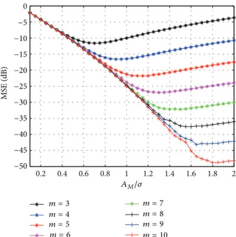
0.2 0.4 0.6 0.8 1 1.2 1.4 1.6 1.8 2 0 −5 −10 −15 −20 −25 −30 −35 −40 −45 −50 MS E (dB) AM/𝜎 m = 3 m = 4 m = 5 m = 6 m = 7 m = 8 m = 9 m = 10
Figure 2: MSE of CIR quantization in function of clipping value, for different number of quantization bits.
terminals are equipped with 4 antennas. The main parameters used in the simulations are based on LTE standard [26]: FFT size of 1024; cyclic prefix of 64; sampling frequency set to 15.36 MHz; subcarrier separation is 15 kHz, subcarrier frequency is 2 GHz, the OFDM symbol duration is 66.7𝜇s, and the modulation is QPSK. For the Doppler quantization strategy we consider 120 km/h as the maximum velocity, which corresponds to a maximum normalized Doppler frequency of 𝑓𝐷𝑇𝑠 = 0.0148. The number of iterations used in simulations of the IMMSE algorithm is 20, since we observe that the gains obtained with more than this number of iterations is negligible (this number was also used in other works such as [9,20]). We adopted the pedestrian ITU BRAN B channel, with 6 paths in the power delay profile according to [27]. We assume perfect CSI estimation at receiver side (i.e., at the UT). We consider uniform quantizers with2𝑚levels and normalized saturation level𝐴𝑀/𝜎, with 2𝜎2 = 𝐸[|ℎ𝑙|2], with 𝑙 = 1, . . . , 𝑁.
Figure 2shows the impact of the normalized saturation level𝐴𝑀/𝜎 and the number of quantization 𝑚 on SQNR. As can be observed, there is an optimum normalized saturation level for each value of 𝑚, since the quantizer’s saturation becomes too frequent if𝐴𝑀/𝜎 is small and the quantization interval becomes too high when𝐴𝑀/𝜎 is high. Hereinafter, we assume always the optimum saturation level for each value of𝑚 in the proposed quantization schemes.
Performances of IA algorithms are presented in terms of the average bit error rate (BER) as a function of𝐸𝑏/𝑁0, with 𝐸𝑏denoting the average bit energy and𝑁0denoting the one-sided noise power spectral density.
Figures3–7show the impact of quantization on the BER performance for 𝑚 equals 4, 6, and 8 bits and for perfect knowledge of CSI (no CSI quantization). The results are pre-sented for the closed-form MMSE and IMMSE approaches.
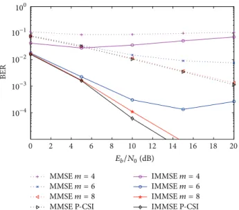
0 2 4 6 8 10 12 14 16 18 20 BER MMSE m = 4 MMSE m = 6 MMSE m = 8 MMSE P-CSI IMMSE m = 4 IMMSE m = 6 IMMSE m = 8 IMMSE P-CSI 100 10−1 10−2 10−3 10−4 Eb/N0(dB)
Figure 3: Performance of IA MMSE and IMMSE algorithms with CIR-QI quantization, for different number of quantization bits.
0 2 4 6 8 10 12 14 16 18 20 BER MMSE m = 4 MMSE m = 6 MMSE m = 8 MMSE P-CSI IMMSE m = 4 IMMSE m = 6 IMMSE m = 8 IMMSE P-CSI 100 10−1 10−2 10−3 10−4 Eb/N0(dB)
Figure 4: Performance of IA MMSE and IMMSE algorithms with CIR-AP quantization, for different number of quantization bits.
We considered the four approaches for CIR quantization, presented inSection 3. In the case of quantization of real and imaginary parts of the non-zero components of CIR (CIR-QI), the performances are shown inFigure 3. As expected, the quantization degrades the system’s performance. Increasing the number of quantization bits, the performance of the IA algorithms tends to the ones obtained with perfect CSI. For 𝑚 = 6 the performance penalty is not significant for low and medium values of𝐸𝑏/𝑁0. For 𝑚 = 8, we can see that the performance is very close to the one obtained for perfect CSI.
Figure 4 depicts the BER performance comparisons for the same schemes, but considering the CIR quantization in terms of amplitude and phase (CIR-AP). The IA algorithms present a slightly higher degradation than the previous one,
0 2 4 6 8 10 12 14 16 18 20 BER MMSE m = 4 MMSE m = 6 MMSE m = 8 MMSE P-CSI IMMSE m = 4 IMMSE m = 6 IMMSE m = 8 IMMSE P-CSI 100 10−1 10−2 10−3 10−4 Eb/N0(dB)
Figure 5: Performance of IA MMSE and IMMSE algorithms with CIR-P quantization, for different number of quantization bits.
0 2 4 6 8 10 12 14 16 18 20 BER 10−1 10−2 10−3 10−4 Eb/N0(dB) MMSE P-CSI IMMSE P-CSI MMSE I = 0 IMMSE I = 0 IMMSE I = 10 IMMSE I = 20 IMMSE I = 30 IMMSE I = 40
Figure 6: Performance of IA MMSE and proposed IMMSE
algo-rithms, with CIR-D, for𝑚 = 6 bits.
mainly for low number of quantization bits, since the quanti-zation characteristic amplitude is larger for the quantiquanti-zation of the phase (from 0 to2𝜋) than for the real and imaginary components of the CIR samples.
InFigure 5, the plots for the same schemes with the third quantization approach (CIR-P) are presented. In this case, the amplitude for of each non-zero CIR component is just transmitted once for a group of OFDM blocks, reducing the number of bits to approximately one-half of the last case. We observe a slight improvement comparative to the previous case, since this strategy is used in cases of slow-varying channels, thus having almost constant amplitude taps.
Figures 6 and 7show the performance of the IA algo-rithms with the CIR-D quantization for𝑚 = 6 and 8 bits,
0 2 4 6 8 10 12 14 16 18 20 BER 10−1 10−2 10−3 10−4 Eb/N0(dB) MMSE P-CSI IMMSE P-CSI MMSE I = 0 IMMSE I = 0 IMMSE I = 30 IMMSE I = 20 IMMSE I = 40 IMMSE I = 50 IMMSE I = 60
Figure 7: Performance of IA MMSE and proposed-IMMSE
algo-rithms with CIR-D quantization, for𝑚 = 8 bits.
respectively. In this case, the delays amplitude and phase, and the Doppler effect parameters are quantized just for the first OFDM block. For the following ones, an estimation is made according to the quantized parameters. We present the BER performances for a set of𝐼 OFDM blocks after the quantized and fed back OFDM block, with𝐼 = 10, 20, . . . , 50. For the case where 𝑚 = 6 (depicted in Figure 6), there is no significant degradation for 10 OFDM blocks without feedback of CSI. The number of bits needed in this scheme over the ones of the CFR quantization is𝑁𝑓6/𝑁𝑓2= 2𝐿/𝑁CP𝐼 and 𝑁𝑓6/𝑁𝑓3 ≃ 2/𝐼 for CIR-QI. This allows a reduction of about 80% of the overhead comparative to the CIR-QI. It presents some penalty for more than 20 OFDM blocks without feedback, specially for high𝐸𝑏/𝑁0 values. For the scenario represented inFigure 7, we have performances close to the case of perfect CSI for a long set of OFDM blocks, with almost no overhead. For example the CSI is known in BSs for a set of 30 OFDM symbols with just a penalty of 1 dB (for a BER of 10−4), only using 0.6% of the quantization bits used in the IA conventional case with CFR where all subcarriers of the channel are quantized (i.e.,𝑁𝑓6/𝑁𝑓2).
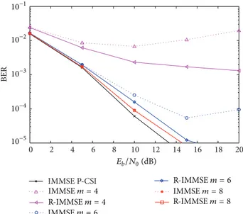
Figure 8 plots the performance of the MMSE, IMMSE, and the proposed R-IMMSE with the CFR feedback strategy, with𝑚 = 6 bits. We observe that the robust algorithm clearly outperforms the nonrobust iterative one, since the robust one is designed taking into account the quantization errors. Also we can observe that the performance gains are higher for medium to high SNR regime, since this is the region where the quantization errors strongly affect the systems performance.
InFigure 9we compare the performance of the proposed robust with the non-robust IA MMSE algorithms, for dif-ferent values of 𝑚. From the figure we can observe that the robust algorithm clearly outperforms the conventional one for low to moderate number of quantization bits, and
MMSE P-CSI IMMSE P-CSI R-0 2 4 6 8 10 12 14 16 18 20 BER 10−1 10−2 10−3 10−4 10−5 Eb/N0(dB) MMSE m = 6 IMMSE m = 6 IMMSE m = 6
Figure 8: Performance of IA MMSE, IMMSE, and proposed
R-IMMSE algorithms with CFR quantization, for𝑚 = 6 bits.
0 2 4 6 8 10 12 14 16 18 20 BER 10−1 10−2 10−3 10−4 10−5 Eb/N0(dB) IMMSE P-CSI R-IMMSE m = 6 IMMSE m = 8 IMMSE m = 4 IMMSE m = 4 R-IMMSE m = 8 R-IMMSE m = 6
Figure 9: Performance of IA MMSE and R-IMMSE algorithms with CFR quantization, for different number of quantization bits.
mainly for moderate to high SNR regimes. As expected, when the number of quantization bits increases the robust scheme tends to the conventional one, since the quantization error power tends to zero. For 𝑚 = 8, we can see that the performance of both algorithms is very close to the one obtained for perfect CSI, with less than 0.5 dB of difference for BER = 10−4.
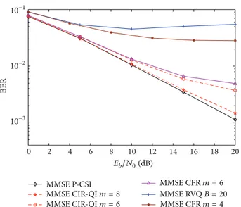
InFigure 10, the RVQ strategy is presented and compared with the proposed CIR-QI quantization. We observe a large penalty in using RVQ with 20 bits per user per antenna. As expected from the analysis in other works using RVQ quantization, the capacity saturates at a constant value if the number of feedback bits is fixed. In [17], the authors improve the multiplexing gain of the proposed scheme by
BER 10−1 10−2 10−3 0 2 4 6 8 10 12 14 16 18 20 Eb/N0(dB) MMSE CFR m = 4 MMSE RVQ B = 20 MMSE CFR m = 6 MMSE CIR-QI m = 6 MMSE CIR-QI m = 8 MMSE P-CSI
Figure 10: Performance of IA MMSE algorithm with CIR-QI, CFR, and RVQ quantizations.
increasing the number of feedback bits scaling with SNR. However, the simulations with more than 20 bits for the RVQ strategy results in a higher computational effort and increases even more the number of feedback overhead. Notice that the overhead rate between CIR-QI and RVQ quantizations is given by𝑁𝑓3/𝑁𝑓1 ≃ 2𝑚𝑀𝐿/𝐵𝑁 bits, which is equivalent to has only 15% of the required feedback overhead with the proposed quantization than with the RVQ, for the simulated system with𝑚 = 6 and 𝐵 = 20, for example. Comparing the RVQ with the CIR-D, the reduction obtained is 1 − 𝑁𝑓6/𝑁𝑓1 ≃ 1 − 4𝑚𝑀𝐿/𝐵𝑁𝐼, which is about 99.7% for the same parameters and 10 OFDM blocks. In the case of more quantization bits being used for RVQ case, our proposal becomes even more advantageous.
6. Conclusions
In this paper, several channel quantization strategies for IA MMSE-multicell-based systems were proposed. The quanti-zation methods require low-complexity and low-bit rates, and imply quantization of different channel parameters: just part of the channel frequency response or only the CIR’s non-zero taps. The considered schemes were studied in detail and evaluated under practical scenarios based on LTE parameters. The proposed algorithms outperform the RVQ-based ones with a large reduction in the required overhead. Moreover, the effect of CSI quantization errors is almost negligible for a reduced number of quantization bits. We also observed the effect of just transmitting the main CSI parameters for one OFDM block and estimated the CSI for the following blocks, drastically reducing the amount of data needed (even when compared with the other proposed strategies with low overhead), presenting lower penalties when comparing with the cases where the CSI is always obtained for each block.
To overcome the penalty introduced by the channel errors due to CSI quantization/estimation in the IA algorithms, we
also proposed a robust iterative IA MMSE-based algorithm, where quantization errors are taken into account in IA design. This algorithm was also evaluated under the proposed limited feedback strategies and clearly outperformed the conven-tional iterative IA MMSE algorithm, mainly for medium and high SNR.
The proposed techniques are of great importance to practical systems, where it is impossible to avoid CSI errors, showing to have performances close to the ones with perfect knowledge of CSI and with lower complexity and overhead than the RVQ-based approaches.
Conflict of Interests
The authors declare that there is no conflict of interests regarding the publication of this paper.
Acknowledgments
This work was supported by the Portuguese FCT (Fundac¸˜ao para a Ciˆencia e Tecnologia) Projects ADIN (PTDC/EEI-TEL/2990/2012), CROWN (PTDC/EEA-TEL/115828/09) and COPWIN (PTDC/EEI-TEL/1417/2012), and the FCT Grant for the first author (SFRH/BPD/79707/2011).
References
[1] D. Gesbert, S. Hanly, H. Huang, S. Shamai, O. Simeone, and W. Yu, “Multi-cell MIMO cooperative networks: a new look at interference,” IEEE Journal on Selected Areas in
Communica-tions, vol. 28, no. 9, pp. 1380–1408, 2010.
[2] D. Castanheira and A. Gameiro, “Distributed antenna system capacity scaling,” IEEE Wireless Communications, vol. 17, no. 3, pp. 68–75, 2010.
[3] 3GPP, “Coordinated multi-point operation for LTE physical layer aspects,” Tech. Rep. 3GPP TR 36. 819, 2011.
[4] M. A. Maddah-Ali, A. S. Motahari, and A. K. Khandani, “Com-munication over MIMO X channels: interference alignment, decomposition, and performance analysis,” IEEE Transactions
on Information Theory, vol. 54, no. 8, pp. 3457–3470, 2008.
[5] V. R. Cadambe and S. A. Jafar, “Interference alignment and degrees of freedom of the K-user interference channel,” IEEE
Transactions on Information Theory, vol. 54, no. 8, pp. 3425–
3441, 2008.
[6] H. Sung, S. Park, K. Lee, and I. Lee, “A two-stage precoding method based on interference alignment for interference chan-nel systems,” in Proceedings of the IEEE Global
Telecommuni-cations Conference (GLOBECOM ’09), Hawaii, Hawaii, USA,
November 2009.
[7] K. Gomadam, V. R. Cadambe, and S. A. Jafar, “A distributed numerical approach to interference alignment and applications to wireless interference networks,” IEEE Transactions on
Infor-mation Theory, vol. 57, no. 6, pp. 3309–3322, 2011.
[8] H. Shen, B. Li, M. Tao, and Y. Lou, “The new interference align-ment scheme for MIMO interference channel,” in Proceedings of
the IEEE Wireless Communications and Networking Conference (WCNC ’10), Sydney, Australia, April 2010.
[9] S. W. Peters and R. W. Heath Jr., “Cooperative algorithms for MIMO interference channels,” IEEE Transactions on Vehicular
[10] R. Tresch and M. Guillaud, “Cellular interference alignment with imperfect channel knowledge,” in Proceedings of the IEEE
International Conference on Communications Workshops (ICC ’09), Dresden, Germany, June 2009.
[11] C. Suh, M. Ho, and D. N. C. Tse, “Downlink interference alignment,” IEEE Transactions on Communications, vol. 59, no. 9, pp. 2616–2626, 2011.
[12] K. Gomadam, V. R. Cadambe, and S. A. Jafar, “Approaching the capacity of wireless networks Through distributed interference alignment,” in Proceedings of the IEEE Global
Telecommuni-cations Conference (GLOBECOM ’08), pp. 4260–4265, New
Orleans, La, USA, December 2008.
[13] O. El Ayatch, S. W. Peters, and R. W. Heath, “The practical challenges of interference alignment,” IEEE Wireless
Communi-cations Magazine, vol. 20, no. 1, pp. 35–42, 2012.
[14] O. E. Ayach and R. W. Heath, “Interference alignment with analog channel state feedback,” IEEE Transactions on Wireless
Communications, vol. 11, no. 2, pp. 626–636, 2012.
[15] R. T. Krishnamachari and M. K. Varanasi, “Interference align-ment under limited feedback for MIMO interference channels,” in Proceedings of the IEEE International Symposium on
Informa-tion Theory (ISIT ’10), pp. 619–623, Austin, Tex, USA, June 2010.
[16] J. Kim, S. Moon, S. Lee, and I. Lee, “A new channel quantization strategy for MIMO interference alignment with limited feed-back,” IEEE Transactions on Wireless Communications, vol. 11, no. 1, pp. 358–366, 2012.
[17] H. Lee and Y. Ko, “Interference alignment with random vector quantization for MIMO interference channels,” in Proceedings
of the 76th IEEE Vehicular Technology Conference (VTC-Fall ’12),
Qu´ebec City, Canada, September 2012.
[18] J. Thukral and H. B¨olcskei, “Interference alignment with limited feedback,” in Proceedings of the IEEE International Symposium
on Information Theory (ISIT ’09), pp. 1759–1763, Seoul, Republic
of Korea, July 2009.
[19] N. Jindal, “MIMO broadcast channels with finite-rate feedback,”
IEEE Transactions on Information Theory, vol. 52, no. 11, pp.
5045–5060, 2006.
[20] S. Teodoro, A. Silva, R. Dinis, and A. Gameiro, “MMSE inter-ference alignment algorithms with low bit rate feedback,” in
Pro-ceedings of the Wireless Personal Multimedia Communications Symposium (WPMC ’13), Atlantic City, NJ, USA, June 2013.
[21] C. M. Yetis, T. Gou, S. A. Jafar, and A. H. Kayran, “On feasibility of interference alignment in MIMO interference networks,”
IEEE Transactions on Signal Processing, vol. 58, no. 9, pp. 4771–
4782, 2010.
[22] W. Santipach and M. L. Honig, “Asymptotic capacity of beam-forming with limited feedback,” in Proceedings of the IEEE
Inter-national Symposium on Information Theory, p. 289, Chicago, Ill,
USA, June 2004.
[23] D. Neves, C. Ribeiro, A. Silva, and A. Gameiro, “An iterative pilot-data-aided estimator for SFBC relay-assisted OFDM-based systems,” EURASIP Journal on Advances in Signal
Process-ing, vol. 2012, article 74, 2012.
[24] G. James, D. Burley, P. Dyke, J. Searl, D. Clements, and J. Wright,
Modern Engineering Mathematics, Prentice Hall, Harlow, UK,
3rd edition, 2001.
[25] T. Ara´ujo and R. Dinis, “Performance evaluation of quantiza-tion effects on multicarrier modulated signals,” IEEE
Transac-tions on Vehicular Technology, vol. 56, no. 5, pp. 2922–2930,
2007.
[26] 3rd Generation Partnership Project, “LTE physical layer— general description,” 3GPP TS 36. 201 V8. 1, no. 3, 2007.
[27] ITU Document, Rec. ITU-R., “M. 1225—Guidelines for Evolu-tion of Radio Transmission Technologies for IMT-2000,” ITU-R, 1997.
International Journal of
Aerospace
Engineering
Hindawi Publishing Corporation
http://www.hindawi.com Volume 2014
Robotics
Journal ofHindawi Publishing Corporation
http://www.hindawi.com Volume 2014
Hindawi Publishing Corporation
http://www.hindawi.com Volume 2014 Active and Passive Electronic Components
Control Science and Engineering Journal of
Hindawi Publishing Corporation
http://www.hindawi.com Volume 2014 Machinery
Hindawi Publishing Corporation
http://www.hindawi.com Volume 2014
Hindawi Publishing Corporation http://www.hindawi.com
Journal of
Engineering
Volume 2014
Submit your manuscripts at
http://www.hindawi.com
VLSI Design
Hindawi Publishing Corporation
http://www.hindawi.com Volume 2014
Hindawi Publishing Corporation
http://www.hindawi.com Volume 2014
Shock and Vibration
Hindawi Publishing Corporation
http://www.hindawi.com Volume 2014
Civil Engineering
Advances inAcoustics and VibrationAdvances in
Hindawi Publishing Corporation
http://www.hindawi.com Volume 2014
Hindawi Publishing Corporation
http://www.hindawi.com Volume 2014
Electrical and Computer Engineering
Journal of
Advances in OptoElectronics
Hindawi Publishing Corporation
http://www.hindawi.com Volume 2014
The Scientific
World Journal
Hindawi Publishing Corporation
http://www.hindawi.com Volume 2014
Sensors
Journal of Hindawi Publishing Corporationhttp://www.hindawi.com Volume 2014
Modelling & Simulation in Engineering Hindawi Publishing Corporation
http://www.hindawi.com Volume 2014
Hindawi Publishing Corporation
http://www.hindawi.com Volume 2014
Chemical Engineering
International Journal of Antennas and
Propagation International Journal of
Hindawi Publishing Corporation
http://www.hindawi.com Volume 2014
Hindawi Publishing Corporation
http://www.hindawi.com Volume 2014 Navigation and Observation International Journal of
Hindawi Publishing Corporation
http://www.hindawi.com Volume 2014