Localization System and Odometry Fusion
for a Scanning 3 DoF Magnetic Field
Autonomous Robot
Jose Lima1,3(B)and Paulo Costa2,3
1
Polytechnic Institute of Bragan¸ca, Bragan¸ca, Portugal
2
Faculty of Engineering, University of Porto, Porto, Portugal
3
INESC-TEC, Centre for Robotics in Industry and Intelligent Systems, Porto, Portugal
Abstract. Solving the robot localization problem is one of the most necessary requirements for autonomous robots. Several methodologies can be used to determine its location as accurately as possible. What makes this difficult is the existence of uncertainty in the sensing of the robot. The uncertain information needs to be combined in an optimal way. This paper stresses a Kalman filter to combine information from the odometry and Ultra Wide Band Time of Flight distance modules, which lacks the orientation. The proposed system validated in a real developed platform performs the fusion task which outputs position and orientation of the robot. It is used to localize the robot and make a 3 DoF scanning of magnetic field in a room. Other examples can be pointed out with the same localization techniques in service and industrial autonomous robots.
Keywords: Localization
·
Ultra Wideband Time of Flight·
Autonomous mobile robot1
Introduction
An industrial mobile robot requires the ability to self-localize in the environment without human intervention. This means answering the question “Where am I?” from the robot point of view.
Estimating the pose of the robot in a map has been capturing the attention of researchers and developers due to its complexity and the multitude of possible approaches.
Localization systems in industrial environments, are expensive and common to use solutions that rely on artificial landmarks, such as the classic magnetic tape following, line tracking or reflector based laser triangulation [1,2].
c
Springer International Publishing AG 2018
This method has a main disadvantage that requires the installation of ded-icated reflectors for all the environment in the field of view of the robot laser scanner, that in some factories might become an complex and expensive solution. Another localization method can be done resorting to radio frequency mea-suring the signal intensity (Receive Signal Strength Indicator, RSSI). Related problems such as distance errors and multipath effects can be identified in this approach. Instead, distances can be measured resorting to the transit time methodology (Time of Flight, ToF). This method measures the running time of light between a fixed tag module and receiver (Anchor). Ultra-wideband (UWB) modules from Decawave are used in this work. By this way, distances between different fixed tags and anchors can be determined. The distances allow to make the trilateration to estimate the tag position. Unfortunately, this system can only provide the position and not the orientation.
On the other hand, odometry provides the orientation but the cumulative error of localization is a well-known problem. To fulfill this problem, the infor-mation provided by odometry and by the UWB technology is further processed through a data fusion filter (Kalman filter).
This paper presents the data fusion of the UWB ToF distances with the odometry. The Kalman filter combines both information and provides as out-put the position and orientation data. This development allows to validate the concept of data fusion from odometry and UWB ToF distancies and it is imple-mented in a 3 DoF magnetic field sensor robot that scans over a desired path.
The paper is organized as follows: After a brief introduction, Sect.2presents the related work of localization having in mind the UWB technology. Then, Sect.3 addresses the system architecture where the odometry and UWB are described and the UWB localization model is stressed. Section4presents the data fusion from odometry and UWB ToF data whereas Sect.5results of localization and magnetic field scanning are discussed. Finally last section concludes the paper and presents some future work.
2
Related Work
Once mobile robots localization is a complex, challenging and one of the most fundamental problems in the robotics field, there are several approaches in the community. Among the others, laser triangulation, matching algorithms, com-plex vision systems, odometry and radio frequency are methodologies used to find the position of a robot.
Point (ICP) [5,6]. The problem of this approach is the huge amount of data to be processed. The process of finding the correct correspondence between points (matching) is a difficult and time-consuming task.
Another common localization approach is to combine several solutions such as line following and laser triangulation [1,2]. Meanwhile, in the last decade localization based on natural marks has been increasing [7]. These natural marks are composed by a set of distances and angles to the detected objects (such as doors, walls, furniture, . . . ) that can be acquired through an on-board laser range finder. This method has the main advantage of not requiring the installation of dedicated reflectors in the environment, which in some factories might not be a viable option. On the other hand, objects placed in different locations originate measuring errors.
Wireless distance measurement technologies are an increasingly important technology. High accuracy measurements are critical for in-building applications such as autonomous robotic navigation. In these cases, users are requiring ever greater levels of accuracy. Actually, sub-centimeter accuracy can be achieved [4]. The trilateration problem, the process of finding the center of the area of intersection of three spheres, demands a different treatment to other similar solutions, as for example, those based on laser. There are authors that charac-terize the UWB ranges combined with particle filters within a variety of envi-ronments and situations [12] and apply UWB using spatial models [8]. Ultra-wideband (UWB) localization is a recent technology that promises to outper-form many indoor localization methods currently available [9]. UWB has received some attention within the robotics community [17]. It is considered one of the most promising indoor positioning technologies currently available, especially due to its fine time resolution [8]. UWB time of flight has already captured the researchers attention that combines it with inertial sensors [10]. Unfortunately, the orientation cannot be determined with this approach.
Odometry has been used for several years in mobile robots. Knowing the rotation of each wheel and its parameters (such as diameter, distance, friction) it is possible to estimate the posture of the robot on the environment. This is one of the first methodology used to calculate the robot position. A common and basic localization method called dead reckoning (DR) is used to estimate the position by counting wheel rotations with the help of encoders.
However, there are unavoidable accumulated errors for DR based localization over long distances, in that it needs to utilize the previous position to estimate the next relative one and during which, the drift, the wheel slippage, the uneven floor and the uncertainty about the structure of the robot will together cause errors [15]. Due to this cumulative errors it is common to combine different local-ization methods. Several works can be pointed out using the odometry localiza-tion with different approches, such as image processing [13] or Wireless Sensor Network [14].
field scanning in an autonomous way. There are some commercial products like automated scanners but they are remote operated vehicles and not autonomous (example Jireh Industries. As extended work, the localization system could be improved (another Kalman filter input) with the magnetic field acquired data, as shown in [11].
3
System Architecture
A wheeled mobile robot prototype of 28×35 cm (Fig.1) was developed having in mind the scanning of the magnetic field in a room based of the proposed positioning system.
Fig. 1.Mobile robot prototype
It is composed by two drive wheels and a castor wheel. Two stepper motors drive the differential mobile robot, a typical configuration in mobile robots, are powered by Allegro MicroSystems - A4988 modules that handle the microstep-ping method and regulate the current. The maximum speed of the robot is 1 m/s but the tests presented in Results section were achieved with 10% of speed. It is powered by onboard 12 V battery and a DC/DC step down converter allows to supply the electronic modules composed by a Raspberry 3 model and arduino microcontroller boards. The upper level is composed by a Raspberry microcom-puter that runs raspbian operative system and is responsible for the Kalman fil-ter processing, wi-fi communications and decision. The Arduino microcontroller
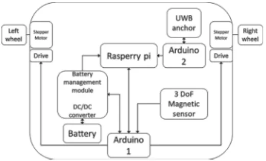
boards deal with the low level control of motors, voltages, current, power man-agement, odometry and acquire the 3 axis magnetic field sensors (HMC5883L). A block diagram of the system is presented in Fig.2.
3.1 Ultra Wideband Time of Flight
Time of flight describes methods that measure the time that an object, particle, electromagnetic or other wave take to travel a distance. It is a technology used, for example, in depth cameras that allows to measure the distance of an object to the camera based on the travel time of the speed of light. Using radio frequency, there are some approaches that estimates the distance measuring the signal strengths (Receive Signal Strength Indicator, RSSI). Results are not much sat-isfactory because signal reflections and multi-path effects introduces errors and noise in measure. The distance between two Ultra Wideband (UWB) devices can be measured precisely by measuring the time that it takes for a radio wave to pass between the two devices. It delivers much more precise distance measure-ment than signal-strength estimation. UWB signals maintain their integrity and structure even in the presence of noise and multi-path effects. It is a technology based on the IEEE 802.15.4-2011 standard, which can enable tagged objects to be located [16].
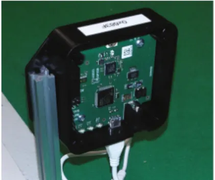
Decawave DW1000 is a single chip, UWB compliant, and Arduino compatible Wireless Transceiver based on Ultra Wideband techniques and provides a new approach to Real Time Location and Indoor Positioning Systems. This module, embedded in the Pozyx system is presented in Fig.3. The presented hardware allows to measure the distance between modules process the (x, y) position.
Fig. 3.UWB Pozyx tag
3.2 UWB - ToF Distances Model
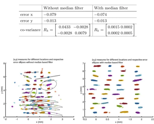
having the tags placed in the bottom corners of a room of 7 × 2.5 m. A pre-filtering process before Kalman filter (a median based gate, shown in Fig.5) must be applied to reject the incoherent measures. In fact, thexandyerrors remain the same but the co-variance is reduced with the proposed filter as presented in Table1 where Rk is the observation noise covariance that will be used in the Kalman filter. Figure4 presents the error ellipses for both methods: at left without median filter gate and at right with it.
Table 1.Error and co-variance values with and without median based filter
Without median filter With median filter
error x −0.079 −0.074
error y −0.013 −0.013
co-variance Rk=
0.0433
−0.0028 −0.0028 0.0079
Rk=
0.0015 0.0002
0.0002 0.0005
Fig. 4. (x,y) measures for different locations and respective error ellipses with and without median filter
4
Localization Data Fusion
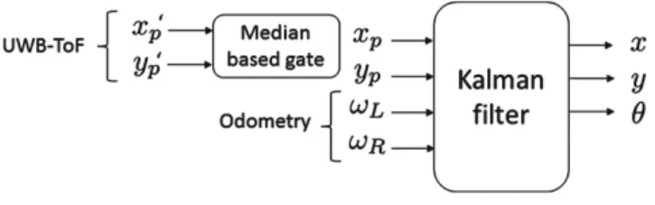
This section presents the Kalman filter that receives the odometry and the UWB modules position information and outputs the position and orientation. The median based gate filters the position provided by the ultra wide band time of flight module (UWB-ToF),x′
andωR (left and right wheel speeds) from the odometry system. The output of the filter (Xk in Eq.1) is composed byx,y andθthat is the robot position and orientation as presented in Fig.5. In this case, the height of all tags and anchor was the same.
Fig. 5.Kalman filter inputs/outputs.
The first filtering approach, the median filter presented in previous section, is applied. The filtered values (x and y values to set the center of the gate that eliminates unlikely measures) are the input for the Kalman filter.
Xk= ⎡
⎣ x y θ
⎤
⎦ (1)
˙
X=f(X, u) (2)
where
u=
v ω
(3)
The observation estimate,Z:
Z =h(X) (4)
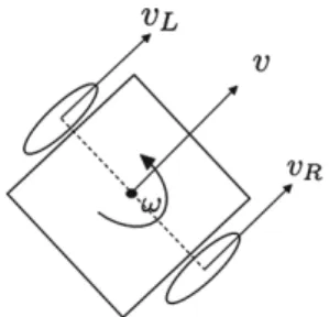
From odometry (Fig.6), vL = ωL.r and vR = ωR.r where r is the wheel radius.
The linear velocity (v) and angular velocity (ω) can be calculated as presented in Eq.5wheredis the distance between wheels that equals 0.29 m.
v= vL+vR
2 ω=
vR−vL
d (5)
Equation2( ˙X) can now be calculated as: ⎡
⎣ ˙ x
˙ y ˙ θ
⎤
⎦= ⎡
⎣
v.cos(θ) v.sin(θ)
ω ⎤
Fig. 6.Robot velocity vectors.
Fk is the state transition model which is applied to the previous stateXk−1, expressed in Eq.7 where∆tis the time step for the acquisition.
Fk = ⎡
⎣
1 0−∆t.v.sin(θ) 0 1 ∆t.v.cos(θ)
0 0 1
⎤
⎦ (7)
The Jacobian ofhfunction is:
Hk=
1 0 0 0 1 0
(8)
The measurement from UWB-ToF isZk:
Zk =
xp yp
(9)
Predict. This subsection addresses the predict of state. The predict covariance estimate,Pk− (untilkinstant).
Pk−=Fk−1Pk−1Fk′−1+Qk−1 (10)
where Fk is the state transition model which is applied to the previous state xk−1andQk−1is the process noise covariance. TheQk−1 matrix can be written as Eq.11.
Qk−1= ⎡
⎣
cov(vx, vx)cov(vx, vy)cov(vx, ω) cov(vx, vy)cov(vy, vy)cov(vy, ω) cov(vx, ω) cov(vy, ω) cov(ω, ω) ⎤
⎦ (11)
Instead of working withvx andvy, it is possible to perform a rotation Rot (Eq.12) to work withv andvn (wherev is the linear velocity whereasvn is the normal velocity) we can assumevn= 0 and cov(vn, vn) =σ2n.
⎡ ⎣ vx vy ω ⎤ ⎦= ⎡ ⎣
cos(θ)−sin(θ) 0 sin(θ) cos(θ) 0
0 0 1
Working withvandvn,Qk−1=Rot·Q′k−1·RotT, whereQ′k−1is presented in Eq.13, it is possible to reach the ratio betweencov(v, v) andcov(ω, ω) presented in Eq.16, assuming that vL and vR errors follows a normal distribution (N) centred in zero with a standard deviation ofσo. Equations14and15present the distribution ofv andω.
Q′ k−1=
⎡
⎣
cov(v, v) 0 0 0 cov(vn, vn) 0
0 0 cov(ω, ω)
⎤
⎦ (13)
v→2· 14·N(0, σ2o) (14)
ω→2·d12 ·N(0, σ 2
o) (15)
cov(v, v) = 4
d2cov(ω, ω) (16) This methodology allows to tune the Kalman filter by two constants (σo, σn) that can be found by performing a few experiences.
The prediction state estimate,Xk− (untilk instant)
Xk− =f ∗(X
k−1, uk−1) (17)
Update. This subsection addresses the Update process. The measurement residual:
˜
Yk=Zk−Z (18)
The innovation covariance:
Sk=HkPk−Hk′ +Rk (19)
where Rk is the observation noise covariance, that can be calculated based on the covariance average of measures points from previous subsection as presented in Table1.
The Kalman gain,Kk:
Kk=Pk−H ′
kS−1k (20)
The updated state estimate,Xk:
Xk =Xk−+KkY˜k (21)
The updated covariance estimate,Pk can be described:
5
Results
The localization system under validation was tested in the developed robot on a corridor of 7 m×2.5 m (x,y). The output stateXk of the Kalman filter allows to control the robot to follow the desired path presented in Fig.7(the controller will be addressed in a future work). The tags were placed in the corners, as presented in Fig.7 by blue circles and the scanning was performed according to the presented path. Start position is (0, 0.5) and the end position is (2, 0.5).
Fig. 7.Scanning path
Obviously, this is only for localization demonstration purpose. Otherwise, a more detailed scan could be performed. Euclidean Mean absolute error associated with the proposed methodology is about 6 cm. A ground truth system will be applied to validate the presented approach as future work. The scan with the 3 DoF magnetic field sensor allows to measure the magnetic field value in x, y andz directions. Figure8 presents the direction of thexandy vectors whereas Fig.9 presents thex,y andzvectors magnitude.
The disturbances in the magnetic field orientation and magnitude are explained by metallic underground boxes.
Fig. 9.Magnetic field magnitude plot
6
Conclusion and Future Work
The presented paper proposes a robot localization system based on odometry and ultra wideband time-of-flight. This sensor fusion allows to estimate the ori-entation of the robot that UWB ToF lacks. The data fusion is processed by a Kalman filter and the implementation of a pre filtering system composed by a median based gate allows to reduce the covariance. Thus, localization error is reduced. As implementation, a 3 DoF magnetic field scan is done in a floor of a corridor that finds the underground hidden metallic objects.
As future work, Kalman filter inputs can be added such as the previous known scanned magnetic field, accelerometer/gyroscope and visual localization to improve the localization of the robot. Also, a ground truth system will be applied to validate the presented approach.
References
1. Schulze, L., A.: Wullner, A.: The approach of automated guided vehicle systems. In: 2006 IEEE International Conference on Service Operations and Logistics, and Informatics, pp. 522–527 (2006)
2. Schulze, L., Behling, S., Buhrs, S.: Automated guided vehicle systems: a driver for increased business performance. In Proceedings of International Multiconference of Engineers and Computer Scientists, pp. 19–21 (2008)
3. Lauer, M., Lange, S., Riedmiller, M.: Calculating the perfect match: an efficient and accurate approach for robot self-localization. In: RoboCup 2005: Robot Soccer World Cup IX, pp. 142–153 (2006)
4. Petroff, A.M.: Ultra wideband two-way time-of-flight distance measurement pro-vides sub-centimeter range measurement accuracy. In: Radio Science Meeting (Joint with AP-S Symposium) (2015)
5. Besl, P.J., McKay, H.D.: A method for registration of 3-D shapes. IEEE Trans. Pattern Anal. Mach. Intell.14(2), 239–256 (1992)
6. Censi, A.: An ICP variant using a point-to-line metric. In: 2008 IEEE International Conference on Robotics and Automation, pp. 19–25 (2008)
7. Tomatis, N.: BlueBotics: navigation for the clever robot [entrepreneur]. IEEE Robot. Autom. Mag.18(2), 14–16 (2011)
8. Prorok, A., Martinoli, A.: Accurate indoor localization with ultra-wideband using spatial models and collaboration. Int. J. Robot. Res.33(4), 547–568 (2014) 9. Prorok, A., Martinoli, A.: Accurate localization with ultra-wideband: tessellated
spatial models and collaboration. In: 13th International Symposium on Experi-mental Robotics (2013)
10. Kok, M., Hol, J.D., Sch¨on, T.B.: Indoor positioning using ultrawideband and iner-tial measurements. IEEE Trans. Veh. Technol.64(4), 1293–1303 (2015)
11. Rahok, S.A., Shikanai, Y., Ozaki, K.: Trajectory tracking using environmental magnetic field for outdoor autonomous mobile robots. In: IEEE/RSJ International Conference on Intelligent Robots and Systems, Taiwan (2010)
12. Gonzalez, J., Blanco, J.L., Galindo, C., Ortiz-de-Galisteo, A., Fernandez-Madrigal, J.A., Moreno, F.A., Martinez, J.L.: Mobile robot localization based on ultra-wide-band ranging: a particle filter approach. Robot. Auton. Syst.57(5), 496–507 (2009) 13. Pizarro, D., Mazo, M., Santiso, E., Marron, M., Jimenez, D., Cobreces, S., Losada, C.: Localization of mobile robots using odometry and an external vision sensor. Sensors10, 3655–3680 (2010)
14. Fu, G., Zhang, J., Chen, W., Peng, F., Yang, P., Chen, C.: Precise localization of mobile robots via odometry and wireless sensor network. Int. J. Adv. Rob. Syst.
10, 203–213 (2013)
15. Borenstein, J., Feng, L.: Measurement and correction of systematic odometry errors in mobile robots. IEEE Trans. Robot. Autom.12(6), 869–880 (1996)
16. Decawave website: UWB transceiver (2017).http://www.decawave.com/