INTRODUCTION
The manufacture of advanced ceramic parts has been challenging around the world, searching ways of making this kind of materials and products useful and proitable in applications that demand reliability in high temperatures [1]. There are different types of manufacturing processes for advanced ceramics, such as uniaxial-pressing, hot pressing, cold isostatic and hot isostatic pressing, slip casting, tape casting, extrusion, injection molding, gel casting or forming [2]. This research focused on the low pressure injection molding (LPIM) process. LPIM has been argued as an alternative process to produce medium and small quantity and high quality complex shapes of ceramic components in comparison to other possible processes such as high
pressure injection molding. Some of the main advantages are low investment on machine, mold and low energy consumption for small and complex components production [3, 4]. In this process, the feedstock - composed of a main material, i.e. alumina, and an organic vehicle (or binder), is injected into the mold cavities by air pressure [5], producing the green parts. After that, the organic vehicle is removed by the debinding process, and inally the parts are sintered at 1600 °C. Additionally, this type of process allows the production of more complex geometric shapes, satisfactory dimensional tolerances, the use of different materials, through a traditional polymer injection molding process [4, 6, 7]. Traditionally, researches related to LPIM process have usually approached materials composition and its inluence on the inal properties [5]. However, due to
Welding lines formation in holes obtained by low pressure injection
molding of ceramic parts
(Formação de linhas de solda em furos no processo de injeção a baixa
pressão de peças cerâmicas)
C. A. Costa, A. F. Michels, M. E. Kipper
Department of Mechanical Engineering, CCET, University of Caxias do Sul, R. Francisco Getúlio Vargas 1130, PO Box 1352, Caxias do Sul, Brazil 95020-972
Abstract
This work presents a study to evaluate the process of producing internal holes in ceramic disks produced by low pressure injection
molding (LPIM) process. Two process conditions deined as pre-injection and post-injection were used to test the proposition. In the irst one the pin cores that produce the holes were positioned in the cavity before the injection of the feedstock; and in the second one, the pin cores were positioned in the cavity, just after the feeding phase of the injection mold. An experimental injection mold
designed and manufactured to test both processes was developed to produce ceramic disk with Ø 50 x 2 mm with four holes of Ø 5 mm, equally and radially distributed through the disk. The feedstock was composed of 86 wt% alumina (Al2O3) and 14 wt% organic
vehicle based on parafin wax. Heating and cooling systems controlled by a data acquisition system were included in the mold. The
results showed that there were no welding lines with the post-injection process, proving to be an option for creating holes in the
ceramic parts produced by LPIM. It was observed that best results were obtained at 58 °C mold temperature. The pins extraction temperature was about 45 °C, and the injection pressure was 170 kPa.
Keywords: low pressure injection molding, welding lines, holes.
Resumo
Este trabalho apresenta um estudo para avaliar o processo de produção de furos internos em discos cerâmicos produzidos pelo
processo LPIM (moldagem de injeção a baixa pressão). Duas condições de processo deinidas como pré-injeção e pós-injeção
foram usadas para a proposição. No primeiro, os insertos dos pinos que produzem os furos foram posicionados na cavidade antes
da injeção do veículo orgânico; no segundo, os insertos dos pinos foram posicionados na cavidade, logo após a fase de alimentação
do molde de injeção. Um molde de injeção experimental projetado e fabricado para testar ambas condições foi desenvolvido para produzir um disco cerâmico com Ø 50 x 2 mm com quatro furos de Ø 5 mm, igualmente e radialmente distribuídos no disco.
A matéria-prima foi composta por 86% em massa de alumina (Al2O3) e 14% em massa de veículo orgânico à base de paraina.
Sistemas de aquecimento e refrigeração controlados por um sistema de aquisição de dados foram incluídos no molde. Os resultados mostraram que não houve linhas de solda com o processo de pós-injeção, provando ser uma opção para criar furos nas peças
cerâmicas produzidas pelo LPIM. Observou-se que os melhores resultados foram obtidos a 58 °C como temperatura do molde na injeção. A temperatura de extração dos pinos foi de 45 °C e a pressão de injeção foi de 170 kPa.
the brittle characteristics of the green parts and shrinkage, during and after the cooling cycle, this work has focused on an alternative approach for producing holes in lat geometry parts. In a previous work [8], a study identiied the temperature range to extract the core in cup-shaped type parts, i.e. when the feedstock is almost solidiied and it has not started the shrinkage process. However, that study revealed one alternative approach to punch the holes just after the injection process, avoiding welding lines. In order to perform this initial study, a disk geometry of Ø 50 mm x 2 mm was chosen to include four holes of 5 mm distributed radially. The disk geometry was chosen as previous work was developed with this geometry, being the process parameters well known. An experimental two cavity mold was designed with two extraction systems: pre and post cavity feeding phase.
The manufacturing of ceramic parts by LPIM process can be divided into four main steps: selection and preparation of feedstock (material); injection molding process; organic vehicle removal; and inal sintering [5, 9]. In LPIM, the ceramic powder is mixed with other materials that form the organic vehicle, also called organic binder, which can be composed of elements such as parafin, waxes and oils, resulting in good luidity and low viscosity feedstock. Thus, the feedstock has primordial importance in this process [10, 11]. On one hand this provides good viscosity for the mixture; on the other hand, it may become a problem considering its further extraction, in the range of 30 to 40% in volume, usually related to shrinkage, deformations and defects formation [6]. The mixture is heated in the machine tank (between 60 to 100 °C to wax based binders) providing a low viscosity to the feedstock and allowing its transfer to the injection mold by air pressure. Injection pressures are low (between 150 kPa e 1 MPa) when compared to traditional injection molding [12]. The feedstock is cooled in the injection mold producing the solid green parts. After their extraction, these green parts go to the binder removal phase and after that to the inal sintering process. The injection phase, i.e. feeding, cooling and extraction of the part, is usually fast, allowing the production of small lots of parts. Green parts are fragile and must be handled with care. If necessary, at this stage, the parts can be adjusted by additional manufacturing process [5]. The main aspects, alone or combined, which may affect the results of this process are: mold design, cooling process, material rheology, injection molding and machine parameters, such as tank temperature, injection pressure, injection feeding time, etc. [5, 13]. The proper control of such variables results in parts free of defects and free of residual stress, which can strongly affect the downstream phases of this process [13, 14]. The temperature difference between the feedstock and mold cavities is very important in this process. Therefore, temperature difference around 50 °C are recommended to produce parts with minimum voids (porosity) and low deformation. Low temperature differences may result in formation of parafin crystals during the cooling process resulting structural differences between layers from interior
to the exterior of the part [5, 7].
One of the disadvantages of LPIM is the time required for the binder removal, which is usually long. Depending on the chosen removal technique it might take from 6 to 40 h [15]. The inal phase is the sintering process based on a thermal consolidation so that the voids are eliminated with the growing of the grain size [12]. The temperatures at this phase are usually around 1600 °C with heating rate of 1 ºC/min and stabilization of 2 h [15]. Another aspect that is critical in LPIM process is the shrinkage associated with the brittle characteristics of the green parts. This is usually a result of waxes addition to composing the feedstock, as it was mentioned before [16]. These waxes and parafin are melted during the feedstock preparation and the injection phase increasing the volume of the feedstock and resulting in a shrinkage during the cooling of the injection mold and the solidiication of the part. Approaches such as the overshot are not possible because of the range of applied pressure (usually under 0.7 MPa). Also, the feeding gate usually solidiies quickly making it dificult to control the pressure [17]. Shrinkage is not a great issue to deal with in most components geometry. However, when dealing with holes produced by inserts (core), this becomes a main issue [8], mainly because of the cracks, voids and welding lines. Welding lines in injection molding usually occur because of the separation of the material low, enforced by some obstruction and its posterior junction [18-21]. These welding lines are potentialized by the low part of organic vehicle in the feedstock. Welding lines can result in stress concentration and cracks formation, mainly in LPIM that requires posterior debinding and sintering (Fig. 1). This paper presents an alternative approach to mold holes in ceramics parts created by LPIM. The study compares the process of creating holes by some inserts put into the impression cavity before (called here pre-injection) and after (called here post-injection) feeding the cavity. Figure 1: Welding lines in a ceramic part produced by LPIM process.
MATERIALS AND METHODS
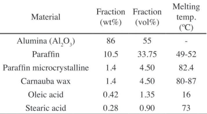
Feedstock: the feedstock used in this research was composed of: 86 wt% Almatis Alumina - Al2O3, d50=0.4 µm; and 14 wt% of organic vehicle based on parafin wax (Table I). In order to produce the inal feedstock, organic vehicle was mixed and melted at 90 °C, then the alumina was added in small portions. After that, the feedstock was processed during 30 h directly into the injection molding machine (Peltsman MIGL-33), with planetary double blade mixer, applying heating and vacuum. This method was used in previous works with good results [8, 14]. The composition presented in Table I was deined in [22] as a result of experimental work and was deined to provide best rheology properties to the LPIM along with a homogenous mass loss distribution during the debinding step within a wide time range. Speciically, to the organic vehicle, components with low molecular weight were used, avoiding the use of polymers.
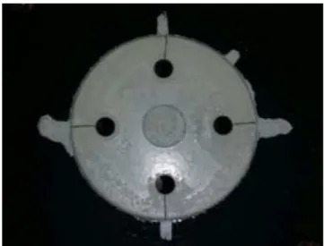
Experimental geometry and injection mold: in order to facilitate the feeding of the cavity, the extraction of the inal parts and the result comparison, a disk shape part was used. This geometry was used in [23] with good results. The dimensions were deined in 50 mm diameter and 2 mm thickness. Additionally, to identify and analyze the welding lines formation, four holes of 5 mm were placed radially and uniformly, 15,5 mm from the disk centre (left side of Fig. 2). Fig. 2 also depicts on the right side the pair core/cavity for the geometry which was deined. The core plate had four holes to guide the core pins. The cavity plate had four indentations of 1,5 mm depth to it the core pins. Venting channels were manufactured with 0.02 mm thickness in order to allow a smoother air escape. Based on this geometry, an experimental injection mold, previously used in [15], was used with some adjustments. Fig. 3 shows a representation of the injection mold. The mold plates were made of aluminum (7075-T6) and had as main function providing structural support and alignment and holding heating, cooling and feeding systems. The heating system was designed based on four Ø 6 x 130 mm cartridge heaters (150 W each) and controlled by a DAQ (Measurement Computing, USB-TC) and thermocouples (K-type), placed at 1 mm of the cavity surface. Temperature
variations were captured every 0.5 s. The cooling system was based on a spiral semi-circular cooling circuit channels with Ø 5 mm machined section to provide uniform cooling of injected parts. Sealing plates with electrolytic cooper were used between the cooling circuit and cavity inserts. A chiller was used on the cooling system with a capacity of 3.5 kW and 8 m3/min low rate. Finally, the feeding system was
based on a central sprue connecting the injection machine feeding channel to the insert cavity. The mold main cavities were covered with polytetraluoroethylene (PTFE, Telon®) to minimize adhesion between part and cavity surface.
To test the two approaches proposed in this work, i.e. core pins placed pre and post-injection feeding phase, a moving structure was developed to allow the positioning of the core pins in the cavity (Fig. 3, right). Thus, for the post-injection approach, as shown in the left side of Fig. 4, the core pins were not placed inside the cavity impression during the feeding phase. Just after this phase, the structure was pressed down (Fig. 4, right side) placing the core pins inside the cavity and creating the holes. In this approach, when the temperature of the mold reached 45 °C, the structure was removed again, leaving the shape to the inal cooling phase, i.e. until 35 °C. For the pre-injection approach, during the feeding phase, the structure with the core pins stayed Table I - Feedstock composition.
[Tabela I - Composição do veículo orgânico.]
Material Fraction (wt%) Fraction (vol%)
Melting temp.
(ºC)
Alumina (Al2O3) 86 55
-Parafin 10.5 33.75 49-52
Parafin microcrystalline 1.4 4.50 82.4
Carnauba wax 1.4 4.50 80-87
Oleic acid 0.42 1.35 16
Stearic acid 0.28 0.90 73
Figure 2: Disk geometry (left) and mold inserts (right) representation.
[Figura 2: Representação da geometria do disco (esquerda) e insertos do molde (direita).]
Alignment holes Cavity
Venting
Pins indentations Guiding for
insert pins
Core
Figure 3: Experimental injection mold designed and used.
[Figura 3: Molde de injeção experimental projetado e utilizado.]
Core pins mechanism
Cooling circuits
Mould superior plate Heaters
holes Mound
plate
Disk cavity
Thermocouple locations Sprue / feeding
Channel Core/cavity
Inserts
Core pins moving mechanism
pressed down, providing the obstructions and the cores to shape the holes in the part. In the same manner, the structure was removed when the mold temperature reached 45 °C.
Experiment conditions: the experiments were carried out with the parameters presented in Table II. These parameters were used in previous works [7, 23, 24], proving to be the most recommended parameters for these applications. Thus, the mold temperature at the injection moment was deined at 58 °C, injection pressure around 170 to 200 kPa, injection time (injection and overshot) of 12 s, and inal extraction temperature for the part at 35 °C. The temperature of 58 °C as initial injection mold temperature was deined based on initial tests in order to provide a smoother condition of pressing the hole core mechanism inside the cavity just after the injection. The mold temperature usually rose about 2 °C just after the injection while the feedstock temperature was 90 °C. In a similar way, the temperature of 45 °C was deined to extract the hole cores (pins). Lower temperature range increased the force for the extraction of the pins and the formation of cracks, while the higher temperature range resulted in the deformation of the hole. At 45 °C, the part was practically solidiied and the force to extract the pins were weaker than the force at 35 °C, when the inal extraction of the part was made.
In relation to organic vehicle removal, the heating ramps were the same used in [23] (Fig. 5). It was carried out a process of debinding by wicking at 250 °C during 36 h, followed by a debinding process at 1000 °C for 1 h,
using a Sanchis B CER mufle furnace. Final sintering was performed at 1600 °C during 2 h in a Termolab MLR17 furnace, with Kanthal Super heating elements (molybdenum disilicide) and oxidizing atmosphere. At the end of this process the samples were left inside the furnace switched off for cooling until the temperature of 250 °C, when the furnace door was opened. This inal cooling process took around 24 h and was important to avoid residual stress in the inal parts.
Final holes analysis: the inal analysis of the cracks or welding lines formation was based on visual observations with an optical microscope, Zeiss Axio Binocular. For this phase, it was deined the area depicted in Fig. 6. This region was chosen because the feeding point is placed at the centre of the part providing a uniform low of material to the cores and forming the welding lines. Both inal diameter and circularity of the hole were measured using an optical Table II - Injection molding process parameters.
[Tabela II - Parâmetros deinidos para o processo de
injeção.]
Parameter Value
Feedstock temperature 90 ºC
Injection mold temperature 58 ºC
Pin core insertion temperature 60 ºC Pin core extraction temperature 45 °C Injection mold temperature on extraction 35 ºC
Injection pressure 0.17-0.20 MPa
Injection time 12 s
Figure 5: Heating curves for debinding and sintering.
[Figura 5: Ciclos térmicos para extração de ligante e sinterização
inal.]
Figure 4: Mechanism for creating pre and post-injection feeding approaches.
[Figura 4: Mecanismo para criar as condições pré e pós-injeção.]
Figure 6: Deined region for weld line and crack formations.
[Figura 6: Região deinida para análise da formação das linhas
de solda e trincas.]
1600
T
emperature (ºC)
1400
1200
1000
800
600
400
200
0 0
Time (h)
5 10 15 20 25 30 35 40
Sintering
Debinding by wicking
measurement equipment, Hexagon Optiv Lite OLM 3020. Two strategies of measuring were used: one by windows (based on the hole geometry from which the circle is deined) and one by points (3 points must be selected and a circle is deined based on them). Twenty-ive samples were injected.
RESULTS AND DISCUSSION
Welding lines analysis
Pre-injection samples: for the optical analysis of the pre-injection condition, seven samples were selected (A1, A2, A12, A18, A19, A23 and A24). These samples presented the best supericial conditions in the holes areas. All samples, in this case, presented welding lines in the four holes, due to the material low obstruction. The welding lines appeared after
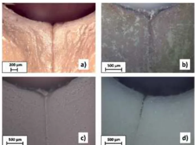
the obstruction following the contour of the hole core (Fig. 1). Fig. 7 depicts the welding line formation to the 4 stages of ceramic processing, i.e. green part (Fig. 7a), debinding by wicking (Fig. 7b), debinding at 1000 ºC (Fig. 7c) and inal sintering at 1600 ºC (Fig. 7d). Under this condition, i.e. pre-injection, there was also the presence of cracks in some holes. In this case, the cracks appeared during the irst stage, i.e. green parts (Fig. 8). On the other hand, the supericial inishing for this condition, i.e. walls and contour of the holes, presented good results.
Post-injection samples: using the same criteria of the previous condition also seven samples were selected for the optical analysis: A7, A8, A10, A15, A21, A22 and A25. In this case, no welding lines or cracks were identiied on the hole perimeters. However, the surface ishing of the holes presented some burrs. These burrs were result of the
Figure 8: Pre-injection condition cracks formation: (a) green part; (b) debinding by wicking; (c) debinding at 1000 0C; (d) sintering at 1600 0C.
[Figura 8: Formação de trincas na condição pré-injeção: (a) peça verde; (b) extração de ligante por leito de pó; (c) extração de ligante a 1000 ºC; (d) sinterização a 1600 ºC.]
Figure 9: Post-injection condition with no welding lines: (a) green part; (b) debinding by wicking; (c) debinding at 1000 0C; (d) sintering at 1600 0C.
[Figura 9: Condição pós-injeção sem linhas de solda: (a) peça verde; (b) extração de ligante por leito de pó; (c) extração de ligante a 1000 ºC; (d) sinterização a 1600 ºC.]
Figure 10: Post-injection condition with burrs formation: (a) green part; (b) debinding by wicking; (c) debinding at 1000 0C; (d) sintering at 1600 0C.
[Figura 10: Formação de rebarbas na condição pós-injeção: (a) peça verde; (b) extração de ligante por leito de pó; (c) extração de ligante a 1000 ºC; (d) sinterização a 1600 ºC.]
Figure 7: Pre-injection condition welding lines: (a) green part; (b) debinding by wicking; (c) debinding at 1000 0C; (d) sintering at 1600 0C.
adhesion between the hole core (insert) surface and the ceramic material, created by the insertion and/or extraction movements. In [15], the core pins were coated with TPBU (Telon®) to avoid the adhesion problems with good results.
This was not tested in this work. Figs. 9 and 10 show the results for this condition. In Fig. 10 the presence of burrs can be observed.
Dimensional analysis
Measurements of the hole diameters and circularities was performed in a proile projector by two different strategies as mentioned above: by points and by window. Measurements were taken in the four stages: green parts, debinding by wicking, debinding at 1000 ºC and inal sintering at 1600 ºC. Reference diameters of the 4 pins in the mold insert were also measured with a calliper Mitutoyo (resolution 0.05 mm). A value of diameter of 5.15±0.05 mm was found and used as reference (dm) to compare with the values of the holes obtained in the parts (df). Based on these values the shrinkage of the holes was calculated (Eq. A) and is presented in Table III.
%Re =dm - dfdm . 100% (A)
For the pre-injection condition, the average value of hole diameter was 5.03 mm, with a standard deviation of 0.03 mm and the shrinkage of the green parts was around 2.2%. This value was the expected considering the feedstock used in [23]. For the post-injection condition the average value of diameter was 5.05 mm, with a standard deviation of 0.05 mm and a shrinkage value of 1.93%. In this case, although the difference was not signiicant, the smaller shrinkage can be due to the material compaction during the penetration of the core pins (Table III). The average value of the hole diameter was a composition of the diameters obtained by the two strategies of measurement, i.e. points and window. The diameter and shrinkage averages were calculated during the four phases of the ceramic material post-processing, i.e. green parts, debinding by wicking, debinding at 1000 ºC and inal sintering at 1600 ºC (Table III). The shrinkage was calculated considering the diameter of the core pins, i.e. 5.15 mm. The diameter averages to the post-injection condition were slightly larger than the pre-injection condition. However, considering the inal
Table III - Average of hole diameter and shrinkage after the four processing phases. [Tabela III - Média do diâmetro e da retração dos furos nas 4 fases de processamento.]
Processing phase No. of samples
Pre-injection Post-injection
Diameter (mm) Shrinkage Diameter (mm) Shrinkage
Green part 19 5.034 2.2% 5.030 1.9%
Debinding by wicking 13 4.939 4.1% 5.003 2.9%
Debinding at 1000 ºC 13 4.908 4.7% 4.952 3.8%
Sintering 1600 ºC 7 4.293 16.6% 4.306 16.4%
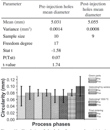
Table IV - t-test’s statistic for diameters.
[Tabela IV - Análise estatística t-test para os diâmetros dos furos.]
Parameter
Pre-injection holes mean diameter
Post-injection holes mean
diameter
Mean (mm) 5.031 5.055
Variance (mm2) 0.0014 0.0008
Sample size 10 9
Freedom degree 17
Stat t -1.58
P(T≤t) 0.07
t-value 1.74
sintering, there were no signiicant differences, due to the extraction of the organic material (16% in volume of the feedstock). As mentioned before, the diameter for the post condition suffers from the insertion and extraction of the core pins, where some material was removed by the adhesion. Pre-injection holes mean diameters were compared with post-injection holes by t-test statistic with a signiicance level of 0.05 as shown in Table IV. Within the uncertainties of the measurements, acceptance of the hypothesis Ho was attained, indicating no difference between the averages of the holes in the two experimental conditions, i.e. the post-injection drilling process does not affect the diameter and contraction results.
Fig. 11 depicts the average values of circularity for Figure 11: Circularity of the holes for pre and post-injection conditions during the four processing phases.
[Figura 11: Circularidade dos furos nas condições pré e pós-injeção durante as 4 fases de processamento.]
0.12
0.06 0.10
0.04 0.08
0.02
0.00
Circularity (mm)
Grenn parts
Debindingf by wicking
Debindingf 1000 ºC
Final sintering Pre
Pre
Pre
Pre Pos
Pos
Pos
Pos
each phase of the ceramic part processing, considering the two injection conditions, i.e. pre and post-injection. Post-injection condition presented higher values of circularity for green parts and inal sintering phase, with also higher dispersion. As mentioned before, the inishing surface of the pre-injection condition was better than the post-injection condition, therefore this is also perceived in the circularity of the holes.
CONCLUSIONS
This work presented an alternative approach to producing holes in LPIM ceramic parts, avoiding the formation of welding lines and cracks. The suggested alternative is based on the positioning of core pins just after the feeding phase of the injection process. The injection mold with an experimental extraction system was designed and manufactured providing reliable results. In relation to the injection molding process parameters, best results were found for injection mold temperature at the feeding phase of 55 ºC for pre-injection condition and 58 ºC for post-injection condition. Moreover, the pins extraction temperature of 45 ºC was considered the ideal for both conditions. For the pre-injection conditions, 70% of the holes presented welding lines and cracks while none of the samples obtained with the post-injection condition presented welding lines. However, they showed lower quality on the surface inishing of the holes than the pre-injection condition. In order to minimize this, further study is set to repeat the experiment coating the core pins with Telon®. Another suggestion for future work
is manufacturing parts with different hole geometries and dimensions, using the post-injection drilling system, in order to test different joint of low material formation. Through the statistical analysis of the hole diameters obtained in each experimental conditions, it was possible to verify that the post-injection drilling process does not affect the diameter and contraction results.
ACKNOWLEDGMENTS
Authors would like to thank the inancial support of Fundação de Amparo a Pesquisa do Rio Grande do Sul (FAPERGS), Research Project Proc. 1904-2551/13-8SIAFEM. We also would like to express our gratitude to the University of Caxias do Sul for the support provided.
REFERENCES
[1] J. Rödel, A.B.N. Kounga, M. Weissenberg-Eibl, D. Koch, A. Bierwisch, W. Rossner, M.J. Hoffmann, J. Eur. Ceram. Soc. 29, 9 (2009) 1549.
[2] R.A. Barbieri, C.A. Perottoni, J.R. Zorzi, Int. J. Appl.
Ceram. Technol. 9, 3 (2012) 599.
[3] W. Bauer, M. Gomez, V. Valcárcel, C. Cerecedo, F. Guitián, M. Peltsman, J.E. Zorzi, Ceram. Ind. 156, 5 (2006)
22.
[4] T. Moritz, R. Lenk, Powder Injection Molding Int. 3, 3
(2009) 23.
[5] E. Medvedovski, M. Peltsman, Adv. Appl. Ceram. 111, 5-6 (2012) 333.
[6] R.M. German, A. Bose, Injection molding of metals and ceramics, Metal Powder Ind. Fed., New Jersey (1997).
[7] J.E. Zorzi, C.A. Perottoni, J.A.H. Jornada, Ind. Ceram.
23, 1 (2003) 47.
[8] W.B. Souza, C.A. Costa, C.R. Altaini, M.A. Luciano,
in 7th Int. Conf. Polym. Moulds Innovations, K. Ragaert, L.
Delva, L. Cardon, Ed., Ghent (2016) 126.
[9] H. Zhang, R.M. German, A. Bose, Int. J. Powder Metall.
26, 3 (1990) 217.
[10] M. Müller, W. Bauer, H.J. Ritzhaupt-Kleissl, in 4M
Conf., S. Dimov, W. Menz, Ed., Elsevier, Amsterdan (2005) 203.
[11] R. Knitter, J. Haußelt, B. Loebbecke, J. Eur. Ceram. Soc. 29 (2009) 1595.
[12] D.W. Richerson, Modern ceramic engineering: properties, processing, and use in design, 3rd Ed., Taylor &
Francis, Boca Raton (2006).
[13] J.V. Zampieron, J.P. Soares, F. Mathias, J.L. Rossi, F. Ambrozio, Key Eng. Mater. 189-191 (2001) 610.
[14] A.R. Erickson, H.E. Amaya, Int. Conf. Mater. Powder Techn., DGM, New York (1993) 145.
[15] C.A. Costa, C.R. Altaini, F.R. Visioli, A.P. Baccin, J. Mater. Design App. 231, 1-2 (2017) 187.
[16] E. Harima, “Estudo da moldagem de pós de alumina por injeção com ênfase na formulação e remoção de ligante”, Tese Dr., Un. Fed. Santa Catarina, Florianópolis (2003). [17] M.J. Edirisinghe, J.R.G. Evans, Int. J. High Technol. Ceram. 2, 4 (1986) 249.
[18] H. Rees, Mold engineering, Hanser/Gardner
Publications, New York, U.S. (1995).
[19] S. Krug, J.R.G. Evans, J.H.H. Ter Maat, Br. Ceram. Trans. 98, 4 (1999) 178.
[20] C.H. Wu, W.J. Liang, Polym. Eng. Sci. 45, 7 (2005)
1021.
[21] V.A. Krauss, E.N. Pires, A.N. Klein, M.C. Fredel, Mater. Res. 8, 2 (2005) 187.
[22] J.E. Zorzi, C.A. Perottoni, J.A.H. Jornada, Cerâmica
50, 315 (2004) 202.
[23] E. Thomazi, C.A. Costa, in 6th Int. Conf. Polym. Moulds
Innovations, A.J. Pontes, A.S. Pouzada, Ed., Guimarães (2014) 77.
[24] F.M. Pasquali, C.A. Costa, in 6th Int. Conf. Polym.
Moulds Innovations, A.J. Pontes, A.S. Pouzada, Ed., Guimarães (2014) 303.
(Rec. 28/03/2017, Rev. 01/06/2017, Ac. 24/06/2017)