Measurement of the quantity Practical Peak Voltage
in the radiology practice*
A medição da grandeza practical peak voltage na prática radiológica
Ricardo Andrade Terini1, Maria da Penha Albuquerque Potiens2, Silvio Bruni Herdade3, Marco Aurélio Guedes Pereira4, João dos Santos Justo Pires5, Heber Simões Videira6
OBJECTIVE: The present study was aimed at evaluating the practical peak voltage (PPV) determined from the voltage waveform applied to x-ray tubes and comparing it with some kVp definitions for different types of x-ray equipment: single-phase (full-wave) and three-phase (six-pulse) clinical x-ray generators, and an industrial constant potential apparatus. MATERIALS AND METHODS: The study involved the comparison between invasively measured PPV (with voltage dividers) and values obtained with two commercial non-invasive meters, besides values of other quantities utilized for measuring the x-ray tube peak voltage. The PPV variation with the voltage ripple was also analyzed in the present study. RESULTS: The authors observed that the difference between PPV and the most common peak voltage definitions increases with the ripple. PPV values varied up to 3% and 5%, respectively, in the comparison between invasive and non-invasive measurements with single-phase and three-phase devices. CONCLUSION: The results demonstrated that voltage ripple is the main quantity influencing the invasive or non-invasive PPV determination. Additionally, non-invasively measured PPV values should be evaluated taking into consideration their dependence on the data sample rate and waveform obtained by the device.
Keywords: Practical peak voltage; X-ray tubes; Voltage divider; Voltage waveform; Peak voltage; kVp meters.
OBJETIVO: O objetivo deste trabalho foi estudar a grandeza practical peak voltage (PPV), determinada a partir da forma de onda de tensão aplicada a tubos radiológicos, e compará-la com algumas definições de kVp para diferentes tipos de geradores: monofásico (onda completa, clínico), trifásico (seis pulsos, clínico) e potencial constante (industrial). MATERIAIS E MÉTODOS: O trabalho envolveu a comparação do PPV medido invasivamente (utilizando um divisor de tensão) com a resposta de dois medidores comerciais não invasivos, além dos valores de outras grandezas usadas para medição da tensão de pico aplicada ao tubo de raios X, e a análise da variação do PPV com a ondulação percentual da tensão (ripple). RESULTADOS: Verificou-se que a diferença entre o PPV e as definições mais comuns de tensão de pico aumenta com o ripple. Os va-lores de PPV variaram em até 3% e 5%, respectivamente, na comparação entre medições invasivas e não invasivas feitas com os equipamentos trifásico e monofásico. CONCLUSÃO: Os resultados demonstraram que a principal grandeza de influência que afeta o PPV é o ripple da tensão. Adicionalmente, valores de PPV obtidos com medidores não invasivos devem ser avaliados considerando que eles dependem da taxa de aqui-sição e da forma de onda adquirida pelo instrumento.
Unitermos:Practical peak voltage; Tubos de raios X; Divisores de tensão; Forma de onda; Tensão de pico; Medidores de kVp.
Abstract
Resumo
* Study developed at Seção Técnica de Desenvolvimento Tec-nológico em Saúde – Instituto de Eletrotécnica e Energia da Universidade de São Paulo (IEE-USP), São Paulo, SP, Brazil. Fi-nancial support: Conselho Nacional de Desenvolvimento Cientí-fico e Tecnológico (CNPq).
1. PhD in Physics, Titular Professor, Department of Physics – Pontifícia Universidade Católica de São Paulo (PUC-SP), Re-searcher, Conselho Nacional de Desenvolvimento Científico e Tecnológico (CNPq), Collaborator of Instituto de Eletrotécnica e Energia da Universidade de São Paulo (IEE-USP), São Paulo, SP, Brazil.
2. PhD in Nuclear Technology, Researcher, Instituto de Pes-quisas Energéticas e Nucleares/Comissão Nacional de Energia Nuclear (Ipen/CNEN), São Paulo, SP, Brazil.
3. Private Docent in Physics, Researcher, Conselho Nacional de Desenvolvimento Científico e Tecnológico (CNPq), Collaborator of Instituto de Eletrotécnica e Energia da Universidade de São Paulo (IEE-USP), São Paulo, SP, Brazil.
INTRODUCTION
Justification for PPV
When a quality control procedure is de-veloped in diagnostic radiology, the deter-mination of the peak voltage (kVp) applied to the x-ray tube plays a fundamental role in the evaluation of the system calibration and performance.
It is a well known fact that small varia-tions in kVp values may produce signifi-cant increases in patient absorbed doses, due to the approximately squared
depen-Terini RA, Potiens MPA, Herdade SB, Pereira MAG, Pires JSJ, Videira HS. Measurement of the quantity Practical Peak Voltage in the radiology practice. Radiol Bras. 2009;42(6):389–394.
4. PhD in Nuclear Technology, Chief Engineer, Seção Técnica de Desenvolvimento Tecnológico em Saúde - Instituto de Eletro-técnica e Energia da Universidade de São Paulo (IEE-USP), São Paulo, SP, Brazil.
5. Master in Applied Nuclear Technology, Professor at Univer-sidade Paulista (Unip), São Paulo, SP, Brazil.
6. Bachelor of Physics, Supervisor of Radiological Protection (Cyclotron), Centro de Medicina Nuclear do Hospital das Clíni-cas da Faculdade de Medicina da Universidade de São Paulo (HC-FMUSP), São Paulo, SP, Brazil.
Mailing address: Dr. Ricardo Andrade Terini. Faculdade de Ciências Exatas e Tecnologia, PUC-SP. Rua Marquês de Parana-guá, 111, Consolação. São Paulo, SP, Brazil, 01303-050. E-mail: [email protected]
dence between air kerma and kVp. The relation between variation in tube voltage and variation of absorbed dose will depend upon the part of the body being irradiated and the used kVp range. Martin et al.(1), for
example, have evaluated anteroposterior radiographic views of the abdomen and reported a mean variation of the equivalent dose absorbed by the liver of 3.5% by kVp unit in the range between 60 and 120 kV, 1%/kV between 90 and 100 kV and 13%/ kV between 60 and 70 kV. Another study(2) has demonstrated that a variation in the voltage applied to the tube also produces a significant contribution to the patient ab-sorbed dose due to the scattered beam.
Thus, the accuracy of peak voltage surements and the definition of the mea-sured quantities are of great importance. Several definitions for kVp were created for different purposes(3): kVpabsolute or
kVpmaximum (absolute peak voltage:
maxi-mum voltage values during exposure), kVpmean (mean peak voltage: average of all
maximum values in all voltage cycles dur-ing exposure), kVpeffective (effective peak
voltage), kVeffective (effective voltage),
kVmean (mean voltage), etc., some of them
aiming at evaluating the technical perfor-mance of the system, while others aimed at evaluating the quality of the produced im-ages. Such definitions are not always clear, and there is no complete consensus amongst users (physicists, engineers, phy-sicians, biomedicine practitioners and tech-nicians) on their meaning and correct prac-tical use. Besides that, the Brazilian Min-istry of Health ordinance MS 453(4) of 1998
does not clarify to which definition it re-fers when the tube voltage is several times mentioned, and when defining values and limits in terms of kVp. Commercial peak voltage meters provide readings of differ-ent parameters, which are sometimes indistinctively utilized, for example, to evaluate the tube voltage calibration in clinical systems.
The kVp determination may be both
electrically made, by means of a calibrated
voltage divider coupled with the x-ray tube circuitry, and spectrally(5) made, requiring
a high degree of repeatability. Such meth-ods are typically utilized in laboratories of calibration of ionizing radiation measure-ment instrumeasure-ments such as that of Instituto
de Eletrotécnica e Energia, Universidade de São Paulo (IEE-USP), where recent projects(6) were carried out for the develop-ment of calibration procedures of invasive systems for kVp measurement by means of x-ray beam spectra.
The quantity practical peak voltage (PPV) has been defined in studies devel-oped by researchers of Physikalisch Technische Bundesanstalt (PTB)(7,8) and
was introduced to practical use by the I EC 61676(9) standard as an electrical quantity univocally defined and more strongly re-lated to image contrast than other param-eters most frequently utilized in the calibra-tion, maintenance and quality control of x-ray equipment, such as kVpmean or
kVpabsolute. Currently, PPV is recommended
by the International Electrotechnical Com-mission (IEC)(10) and International Atomic
Energy Agency (IAEA)(11), as the standard
of voltage applied to radiodiagnosis tubes, in the characterization of x-ray beams to be used for the calibration of dose measure-ment devices and noninvasive meters of the voltage applied to such tubes. The Interna-tional Commission on Radiation Units and Measurements (ICRU), in its Report 74(12),
includes the PPV when conceptualizing quantities and units involved with dosim-etry in x-ray methods for imaging diagno-sis.
The use of standardized beams allows the intercomparison of results from differ-ent laboratories, the reproducibility analy-sis and greater reliability on the calibration results. The IEE-USP is accredited by Na-tional Institute of Metrology, Standardiza-tion and Industrial Quality (Inmetro) for calibration tests of kVp meters, and has developed several studies on the measure-ment of PPV(13–15).
Definition of PPV: relationship with CEV
The PPV quantity is equivalent, in value, to the so called contrast equivalent
voltage (CEV)(7,8), which, on its turn, is
de-fined as the voltage value in which the low level contrast, obtained in an exposure pro-duced by a x-ray tube connected to a gen-erator producing any waveform, be equal to the contrast produced by the same x-ray tube connected to a constant voltage gen-erator, utilizing a phantom with a
deter-mined configuration (10 cm of polymethyl methacrylate +1 mm of aluminum, for con-ventional radiology). Thus, CEV is a quan-tity obtained from the ratio of measure-ments performed with ionization chamber of the air kerma values after the polymethyl methacrylate phantom with and without a small 1 mm sheet of aluminum added as a contrast object, for the radiological tube under test and for the standard system of constant potential(16).
On the other hand, according to the I EC 61676(9),PPV is electrically determined
from the acquisition (preferably performed with an invasive meter, or alternatively with a noninvasive one) of the waveform of the voltage applied to the x-ray tube during the exposure, by the expression (1) below, in which Û is the PPV value, Ui
corresponds to the instantaneous values of voltage applied to the tube, acquired in n samples that constitute the waveform; and
wi(Ui) corresponds to the values of defined
polynomials, for the radiodiagnosis range in the mentioned studies(7–9), that weight
each instantaneous value of the applied po-tential Ui.
Û = (1)1
Σ
N wi.Ui1
Σ
Nwi
– for Ui < 20 kV:
w(Ui) = 0;
– for 20 kV ≤ Ui < 36 kV: w(Ui) = e(a. + b. + c);
– for 36 kV ≤ Ui≤ 150 kV:
w(Ui) = d.Ui + e.Ui+ f.Ui+ g.Ui + h;
where a, b, c, d, e, f, g and h are constants given by:
a = –8.646855×10⁻³;
b = 8.170361×10⁻¹;
c = –2.327793×101;
d = 4.310644×10⁻¹⁰;
e = –1.662009×10⁻⁷;
f = 2.30819×10⁻⁵;
g = 1.03082×10⁻⁵;
h = –1.747153×10⁻². Objectives
The present study was aimed at analyz-ing the PPV behavior in conventional
ra-Ui2 Ui
diology, in invasive measurements (in labo-ratory) and noninvasive measurements, with clinical and non clinical emitters, with focus on its dependence on the ripple of voltage applied to the X-ray tube.
Also, with a view on a greater familiar-ity with PPV by users of the results from quality control programs, the behavior of PPV was compared with those of other definitions of peak voltage applied in the radiological practice.
MATERIALS AND METHODS
Equipment utilized
For the measurements performed in the clinical radiodiagnosis range (40–150 kV), the following systems were utilized: a) a Rörix tube, with 124 kV maximum voltage, spinning anode with a tungsten target and 12° angle (gross focus), alternatively con-nected with two high voltage Siemens gen-erators: a single phase one, model Helio-phos 4B, or a three-phase six pulse one; b) an industrial Philips X-ray equipment (Yxlon International X-Ray GmbH) of constant potential (320 kV maximum volt-age), with a MCN 323 tube with fixed tung-sten anode (22° angle) and beryllium win-dow, and MGC40 controller.
The PPV determination requires the acquisition of the voltage waveform. For such purpose, a calibrated invasive voltage divider Radcal model Dynalizer III (Radcal Corp.; Monrovia, USA), with a voltage ratio of 1:20,000, was connected to the cir-cuitry of the single- and three-phase sys-tems. For the constant potential and mam-mography units, the voltage values were directly acquired from the internal voltage divider, previously calibrated by compari-son with the value of the end point of the x-ray spectra produced in each system, measured with a cadmium telluride detec-tor Amptek (Amptek, Inc.; Bedford, USA), according with the method described by Terini et al.(5).
For the readings of voltage values, two data acquisition plates models PCI MIO-16E-4 (16 bit, 8 analogical inputs, 250 kpps maximum rate) and NI 5911 (21 bit, 1 ana-logical input, 1 Mpps maximum rate) (Na-tional Instruments Corp.; Austin, USA) and a personal computer were utilized. A soft-ware based on LabView (National
Instru-ments Corp; Austin, USA) allowed the acquisition of data from the dividers and the calculation of quantities associated to voltage waveform: kVpabsolute, kVpmean,
PPV, exposure time and percentage rate of voltage variation (ripple)(17).
The noninvasive measurements of the x-ray tube voltage were performed by us-ing two instruments: a PTW meter, model Diavolt (PTW; Freiburg, Germany) and a Radcal model 9095 meter (Radcal Corp., Monrovia, USA), whose main technical characteristics are:
a) PTW, Diavolt – measured quantities: kVpmaximum, kVpmean, PPV, mAs and
expo-sure time; voltage resolution: 0.1 kV; volt-age repeatability: ± 1%.
b) Radcal, 9095 – measured quantities (obtained from a worksheet): kVpmean, PPV
and exposure time; voltage resolution: 0.1 kV; voltage repeatability: ± 1%.
Method
The measurements were performed by means of the following steps:
a) invasive determination of the PPV value and some other x-ray tube applied peak voltage definitions for three types of waveforms: single-phase (two pulses), three-phase (six pulses) and constant po-tential, for different reference kVpmean
val-ues. In this case, the data acquisition rate was maintained at 200,000 pps;
b) invasive and noninvasive determina-tion of the PPV value for waveforms of some voltage ripple values (obtained through the variation of the tube current)
for different kVmean values with the
single-phase and three-single-phase systems.
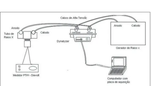
Figure 1 presents an experimental ar-rangement scheme utilized in the measure-ments with the single-phase and three-phase systems. With the other systems, the only difference was the fact that the data acquisition was performed from the x-ray equipment internal voltage divider.
All of the following presented values correspond to averages from three mea-surements. The PPV uncertainties as well as those of the other quantities were ob-tained according with the guidelines in-cluded in the “Guia para expressão da incerteza de medição” (Guidelines for ex-pression of measurement uncertainty) from Associação Brasileira de Normas Técnicas (ABNT)(18). For B type uncertainties, the
information provided by the technical manuals of the voltage dividers and data acquisition plates, as well as the calibration data were considered.
Thus, the PPV values uncertainty was calculated by means of the following ex-pression (2), where uc is the combined
PPV uncertainty, u(Ui) is the uncertainty
of each instantaneous voltage value Ui,
and ∂f/∂Ui is the so called sensitivity
co-efficient for each Ui, among the N values
of the sample, and its value is given imme-diately below. Correlated uncertainties were considered.
(2)
a, b, c, d, e, f, and g having the same
val-ues previously presented in page 390.
RESULTS
Figures 2, 3 and 4 show examples of waveforms acquired with the system de-scribed in the previous section, for each emitting equipment utilized, as well as the
tices that the difference (∆), in kV, between the PPV and the other quantities increases with voltage. On the other hand, Table 3 shows that the difference between PPV and the other quantities remains nearly the same for different voltage values in the constant potential x-ray tube.
Table 4 compares invasively and noninvasively (using the PTW meter) ob-tained PPV values for the three-phase sys-tem. Similar results were obtained with the noninvasive Radcal meter.
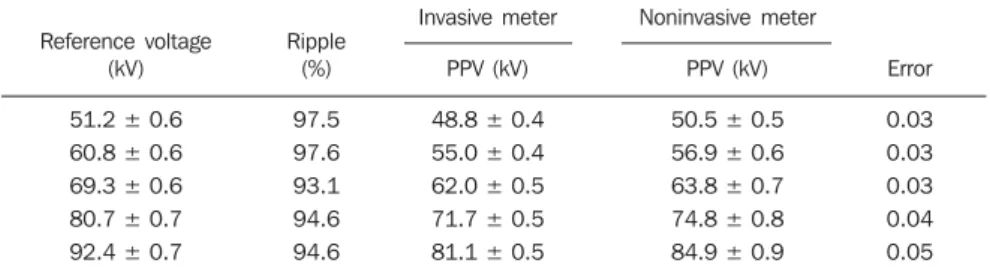
Table 5 presents the invasively and noninvasively (using the Radcal meter) determined PPV values for the single-phase system. Similar results were obtained with the noninvasive PTW meter.
According to the IEC 61676(9) standard, the results for PPV shall not exceed the relative intrinsic error I, calculated accord-ing to the equation (3) and presented on Tables 4 and 5 as “Error”.
Figure 2. Voltage waveform in the x-ray tube for the single-phase equipment with complete wave rectification and values determined for some related physi-cal parameters.
Figure 3. Voltage waveform in the x-ray tube for the three-phase, six-pulse equipment and values determined for some related physical parameters.
Figure 4. Voltage waveform in the x-ray tube for the constant potential equip-ment and values determined for some physical parameters of interest.
Figure 2 Figure 3
Figure 4
where:
respective determined values, in each case, for PPV and other analyzed quantities.
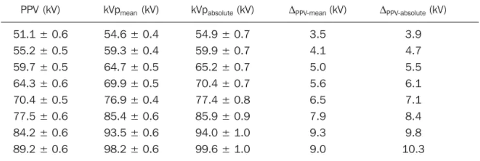
Tables 1, 2, and 3 show the results of the comparison between PPV and other x-ray tube applied peak voltage definitions for three types of waveforms: single phase (two pulses), three phase (six pulses) and constant potential.
no-(3)
where: Ûmeas is the value measured by the
noninvasive meter; Ûtrue is the conventional
true value measured by the reference sys-tem (in this case, the invasive syssys-tem).
DISCUSSION
In the present study x-ray emitting units equipped with voltage generators from dif-ferent generations were utilized, producing several voltage ripple values. This system diversity is still found in many regions throughout Brazil and in some other coun-tries, a different situation from that in Eu-rope, for example, where most of the equip-ment in use are of the high frequency and constant potential type.
As it can be seen on Table 4, the PPV value, invasively measured for three-phase nominal voltage of 100 kV, ranges from 91.4 to 82.8 kV, while the ripple ranges between 15% and 28%. The observed variation in the PPV values corresponds to different contrast levels that would be ex-pected in images obtained with these wave-forms, for a given kVpmean (reference
volt-age). When the results are analyzed, one observes that, except for deviations caused by meter calibration problems, there is a tendency for the intrinsic error to increase as the percentage undulation (ripple) in-creases.
For the single-phase equipment, it was not possible to study the ripple variation for the same reference voltage, on Table 5, however one observes that the difference between the invasively calculated PPV and the noninvasively calculated value in-creases more significantly than in the pre-vious case, as the reference voltage level also increases. Therefore, as previously pointed out, the presented measurement results indicate the need to correct the PPV values obtained with the noninvasive meter used, in the characterization of clinical sys-tems. The cause for the differences with the invasively obtained values seems to be due to the fact that the waveform detected by the noninvasive meter is not complete, i.e., in the calculation of the tube voltage, only instantaneous values higher than a mini-mum (for example, 40 kV) are taken into
Table 1 PPV behavior relative to kVpmean and kVpabsolute for the single-phase equipment in invasive measurements.
PPV (kV)
51.1 ± 0.6
55.2 ± 0.5
59.7 ± 0.5
64.3 ± 0.6
70.4 ± 0.5
77.5 ± 0.6
84.2 ± 0.6
89.2 ± 0.6
kVpmean (kV)
54.6 ± 0.4
59.3 ± 0.4
64.7 ± 0.5
69.9 ± 0.5
76.9 ± 0.4
85.4 ± 0.6
93.5 ± 0.6
98.2 ± 0.6
kVpabsolute (kV)
54.9 ± 0.7
59.9 ± 0.7
65.2 ± 0.7
70.4 ± 0.7
77.4 ± 0.8
85.9 ± 0.9
94.0 ± 1.0
99.6 ± 1.0
∆PPV-mean (kV)
3.5 4.1 5.0 5.6 6.5 7.9 9.3 9.0
∆PPV-absolute (kV)
3.9 4.7 5.5 6.1 7.1 8.4 9.8 10.3
Table 2 PPV behavior relative to kVpmean and kVpabsolute for the three-phase equipment in invasive measurements.
PPV (kV)
57.4 ± 0.4
63.3 ± 0.4
71.8 ± 0.5
78.6 ± 0.5
85.1 ± 0.5
91.8 ± 0.5
kVpmean (kV)
61.6 ± 0.4
68.3 ± 0.3
77.2 ± 0.4
84.5 ± 0.5
92.7 ± 0.5
99.2 ± 0.5
kVpabsolute (kV)
62.3 ± 0.7
69.0 ± 0.8
78.1 ± 0.8
85.4 ± 0.9
93.7 ± 1.0
99.9 ± 1.0
∆PPV-mean (kV)
4.3 4.9 5.5 6.0 7.6 7.4
∆PPV-absolute (kV)
4.9 5.7 6.3 6.8 8.6 8.2
Table 3 PPV behavior relative to kVpmean e kVpabsolute for constant potential equipment in invasive mea-surements.
PPV (kV)
49.2 ± 0.3
59.6 ± 0.4
69.5 ± 0.3
79.9 ± 0.3
89.4 ± 0.3
99.6 ± 0.3
kVpmean (kV)
49.4 ± 0.3
59.9 ± 0.3
69.6 ± 0.4
80.0 ± 0.4
89.5 ± 0.4
99.7 ± 0.4
kVpabsolute (kV)
49.7 ± 0.6
60.1 ± 0.7
69.8 ± 0.7
80.3 ± 0.8
90.1 ± 0.9
99.9 ± 1.0
∆PPV-mean (kV)
0.22 0.23 0.12 0.14 0.12 0.12
∆PPV-absolute (kV)
0.49 0.50 0.36 0.39 0.73 0.39
Table 4 Comparison between invasively measured PPV (Dynalizer) and noninvasively measured PPV (Diavolt) for the three-phase generator. The ripple was varied by means of current variation in the tube. The reference voltage is the kVpmean.
Reference voltage (kV)
60.3 ± 0.6
70.2 ± 0.6
79.4 ± 0.7
90.4 ± 0.7
99.4 ± 0.8
Ripple (%) 16.9 19.7 23.6 11.3 17.0 25.4 9.7 14.2 18.5 8.4 14.3 20.3 14.9 23.1 27.7 Invasive meter PPV (kV)
56.0 ± 0.4 53.5 ± 0.4 51.2 ± 0.5
65.7 ± 0.6 63.8 ± 0.6 58.1 ± 0.5
73.7 ± 0.6 74.0 ± 0.6 72.2 ± 0.6
84.8 ± 0.7 83.0 ± 0.7 79.4 ± 0.7
91.4 ± 0.8 85.8 ± 0.7 82.8 ± 0.7
Noninvasive meter
PPV (kV)
56.7 ± 0.8 54.6 ± 0.8 52.6 ± 0.8
66.5 ± 0.8 64.3 ± 0.9 59.8 ± 0.9
74.8 ± 0.9 75.0 ± 0.9 73.0 ± 0.9
86.4 ± 1.0 85.2 ± 1.0 81.7 ± 1.0
92.6 ± 1.0 87.4 ± 1.1 84.8 ± 1.1
account. This does not affect the determi-nation of peak voltage values, but does interfere on the determination of PPV, which takes into account the whole wave-form.
CONCLUSION
In Europe, the PPV quantity has been in use over the decade since the advent of the first meters capable of measuring it. In Brazil, the discussion is still in the aca-demic field, still with little impact on the radiological practice. Over the last few years, the acquisition of new noninvasive meter models by companies and Brazilian professionals has increased the demand for clarification in the characterization and differentiation of PPV from other known tube voltage definitions.
Today, at least four noninvasive equip-ment models capable of measuring PPV, besides other quantities, are found in the market. The present study was aimed at evaluating the response from two of these noninvasive meters with respect to differ-ent percdiffer-entage waves. The results demon-strated that both meters were, in many points, outside the limits of intrinsic error recommended by IEC 61676 standard (equation 3), which may lead to evaluation errors, mainly in higher ripple clinical sys-tems. This fact demonstrates the need to develop appropriate meters for the reality of equipments currently in use in Brazil, as well as the need to calibrate the available noninvasive meters, not only for the most common definitions of peak voltage, but also in terms of PPV, for different voltages and voltage waveforms, with higher or lower ripple.
At a time when the extension of the PPV concept for a wider range of tensions(19) is
under study for other applications, the in-clusion of PPV, among other topics, in a coming review of MS 453/98 ordinance (4)
would be of great value to consolidate its practical use.
In another study, the results of measure-ments of PPV in mammography will be presented as well as their variation with the data acquisition rate.
Acknowledgments
The authors wish to thank the Physika-lisch Technische Bundesanstalt, for the loan of the noninvasive PTW meter utilized in the present study, and for the invaluable suggestions; the Instituto de Radioproteção e Dosimetria/Comissão Nacional de Ener-gia Nuclear, for the transfer of the data acquisition plate; and the Serviço Técnico de Aplicações Médico-Hospitalares of Instituto de Eletrotécnica e Energia of Universidade de São Paulo and its staff, for the support and possibility of using their infrastructure.
REFERENCES
1. Martin CJ, Sutton DG, Sharp PF. Balancing pa-tient dose and image quality. Appl Radiat Isot. 1999;50:1–19.
2. Fung KKL, Gilboy WB. The effect of beam tube potential variation on gonad dose to patients dur-ing chest radiography investigated usdur-ing high sensitivity LiF: Mg, Cu, P thermoluminescent dosemeters. Br J Radiol. 2001;74:358–67.
3. Ranallo FN. The non invasive measurement of X-ray tube potential [thesis]. Madison: University of Wisconsin-Madison; 1993.
4. Brasil. Ministério da Saúde. Secretaria de Vigi-lância Sanitária. Diretrizes de proteção radioló-gica em radiodiagnóstico médico e odontológico. Portaria no 453/98, de 1/6/1998. Diário Oficial da
União, Brasília; 2 de junho de 1998.
5. Terini RA, Pereira MAG, Künzel R, et al. Com-prehensive analysis of the spectrometric determi-nation of voltage applied to X-ray tubes in the ra-diography and mammography energy ranges us-ing a silicon PIN photodiode. Br J Radiol. 2004; 77:395–404.
6. Piedade PA. Desenvolvimento de um procedi-mento metrológico para calibração de medidores invasivos da tensão aplicada a tubos radiológicos através do espectro dos raios X medido com de-tectores semicondutores. Trabalho de conclusão de curso (graduação em Física). São Paulo: PUC-SP; 2005.
7. Kramer HM, Selbach HJ, Iles WJ. The practical peak voltage of diagnostic X-ray generators. Br J Radiol. 1998;71:200–9.
8. Baorong Y, Kramer HM, Selbach HJ, et al. Ex-perimental determination of practical peak volt-age. Br J Radiol. 2000;73:641–9.
9. International Electrotechnical Commission. Med-ical electrMed-ical equipment – Dosimetric instru-ments used for non-invasive measurement of X-ray tube voltage in diagnostic radiology (IEC 61676:2002). Geneva: International Electrotech-nical Commission; 2002.
10. International Electrotechnical Commission. Med-ical diagnostic X-ray equipment – Radiation con-ditions for use in determination of characteristics (IEC 61267:2005). Geneva: International Electro-technical Commission; 2005.
11. International Atomic Energy Agency. Dosimetry in diagnostic radiology – an international code of practice. Viena: TRS 457; 2007.
12. International Commission on Radiation Units and Measurements. Patient dosimetry for X-rays used in medical imaging. ICRU Report 74. Oxford: University Press; 2005.
13. Pires JSJ, Terini RA, Botttaro M, et al. Depen-dência do potencial de pico prático (PPV) com o “ripple” da forma de onda de tensão aplicada ao tubo de raios X. In: III Iberian Latin American and Caribbean Congress of Medical Physics and IX Brazilian Congress of Medical Physics; 2004 Set 26-29; Rio de Janeiro, RJ. Proceedings in CD. São Paulo: Associação Brasileira de Física Mé-dica; 2004.
14. Pires JSJ, Terini RA, Herdade SB. Determinação da incerteza combinada para o cálculo do poten-cial de pico prático. In: X Congresso Brasileiro de Física Médica; 2005 Mai 26-29; Salvador, BA. Anais em CD. São Paulo: Associação Brasileira de Física Médica; 2005.
15. Pires JSJ, Terini RA, Potiens MPA, et al. Varia-tion of the practical peak voltage with the sample rate for a mammography waveform generator. In: International Nuclear Atlantic Conference (INAC 2007); 2007 Set 30-Out 5; Santos, SP. Proceed-ings in CD. Rio de Janeiro: Associação Brasileira de Energia Nuclear; 2007.
16. Videira HS, Terini RA, Herdade SB, et al. A com-parison between the contrast equivalent voltage (CEV) and the practical peak voltage (PPV) for clinical X-ray systems. In: World Congress on Medical Physics and Biomedical Engineering 2006; 2006 Aug 27-Sep 01; Seoul, Korea. Pro-ceedings in CD. Berlim: Springer-Verlag; 2006. 17. Pires JSJ. Avaliação da grandeza tensão de pico prática em equipamentos clínicos utilizados em radiodiagnóstico [dissertação de mestrado]. São Paulo: IPEN/CNEN-SP; 2007.
18. Associação Brasileira de Normas Técnicas. Guia para expressão da incerteza de medição. 3ª ed. Rio de Janeiro: Associação Brasileira de Normas Téc-nicas; 2003.
19. Kramer HM, Selbach HJ. Extension of the range of definition of the practical peak voltage up to 300 kV. Br J Radiol. 2008;81:693–8.
Table 5 Comparison between invasively (Dynalizer) and noninvasively (9095) measured PPV values for the single-phase generator. The reference voltage is the kVpmean.
Reference voltage (kV)
51.2 ± 0.6 60.8 ± 0.6
69.3 ± 0.6 80.7 ± 0.7
92.4 ± 0.7
Ripple (%)
97.5 97.6
93.1 94.6
94.6
Invasive meter
PPV (kV)
48.8 ± 0.4 55.0 ± 0.4
62.0 ± 0.5 71.7 ± 0.5
81.1 ± 0.5
Noninvasive meter
PPV (kV)
50.5 ± 0.5 56.9 ± 0.6
63.8 ± 0.7 74.8 ± 0.8
84.9 ± 0.9
Error
0.03 0.03
0.03 0.04