Slag Foaming Fundamentals - A Critical Assessment
Rodolfo Arnaldo Montecinos de Almeidaa*, Deisi Vieiraa, Wagner Viana Bielefeldta,
Antônio Cezar Faria Vilelaa
Received: January 25, 2016; Revised: November 28, 2016; Accepted: January 25, 2017
Slag foaming is part of steelmaking process and could bring several beneits: it helps to save energy, improves productivity, enhances the refractory service life, decreases noise pollution and protects the bath from nitrogen incorporation. Unfortunately, slag foaming is a highly dynamic process that is diicult to control. There are factors that limit the quality of the foam generated on the slag, such as: basicity, FeO content, surface tension, viscosity, carbon and oxygen injection. This paper aims to discuss the main factor that induces foaming, mathematical models proposed by diferent authors and the use of isothermal solubility diagram (ISD) to predict the foam quality.
Keywords: Foaming Slag, Electric Arc Furnaces, Steelmaking Slag
* e-mail: [email protected]
1. Introduction
One of the greatest consumers of electricity, electric arc furnaces (EAF), has been the subject of research in the steel production process. The use of fuel burners and oxygen injectors1 assists greater use of chemical energy for a possible
reduction in electrical energy consumption. However, the loss of energy in the form of heat to the furnace walls occurs, and this reduces energy eiciency.
To reduce this loss of energy, studies were focused on the slag, especially on the phenomenon called foamy slag.
Foamy slag is widely used, not only because it allows energy to be saved, but due to the several advantages it ofers, such as 2,3,4:
• Increased energy eiciency, since the heat from the arc is captured by the slag;
• Protection of the water panels and the roof from radiation;
• Decreased noise pollution;
• Decreased nitrogen incorporation by the bath. This paper will make a critical assessment of the foamy slag phenomenon, analyzing the behavior of foamy slag with the variation of basicity, viscosity and chemical composition of the slag.
2. Foamy Slag
2.1. Foamy Slag Formation
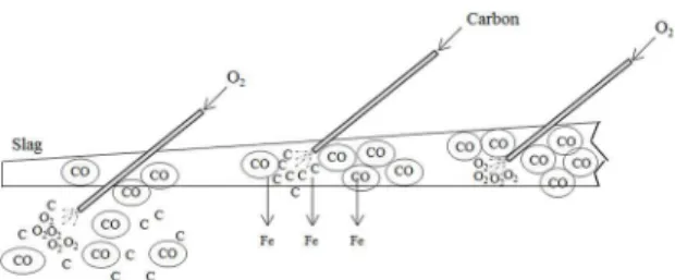
Foamy slag formation can be divided into 3 steps (Figure 1). Step 1, which is O2 injection in liquid steel phase,
step 2, which is carbon injection into the slag, and step 3, which is when O2 is injected into the slag.
a Metallurgy Department, Federal University of Rio Grande do Sul, Av. Bento Gonçalves, 9500,
91501-970, Porto Alegre, RS, Brazil
Figure 1: Diagram showing the formation of CO bubbles.
Initially, oxygen is injected into the molten metal (step 1). This oxygen reacts with the existing carbon (equation 1), forming CO bubbles. The oxygen also reacts with the Fe present in the bath (equation 2).
( )
C
2O
CO
1
1 2
"
+
-( )
Fe
( )l 2O
FeO
2
1 2
"
+
As Fe is lost in the form of oxide, carbon is injected into the slag (step 2), performing the iron oxide reduction reaction (equation 3). This step generates CO gas, and also causes Fe to return to the bath, improving furnace performance.
(
)
( )
C
+
FeO
"
CO
+
Fe
( )l3
In step 3, oxygen is injected into the slag, to cause oxidation of the carbon present in the slag. In this step, carbon and oxygen can also be injected simultaneously, allowing better generation of CO and better foaming.
( )
C
2O
CO
( )
4
1 2
"
In 1998, Pretorius6 stated that the CO generated by the
bath decarburization reaction (Eq. 1) generally results in better foaming than the CO generated in the later steps. The bubbles formed by decarburization reaction in the bath are distributed more uniformly and have a smaller size, providing better stability to the foaming.
Matsuura7 found that the foam produced by iron oxide
reduction reaction had smaller bubbles than those produced by reaction 1, producing more stable foam. He concluded that it is unclear if the decarburization reaction is as efective as the iron oxide reduction reaction in the generation of foam. If the CO from decarburization is neglected, the foaming can be controlled through the amount of carbon and oxygen injected during the process.
It is necessary to control the amounts of C and O added, because if excessive O is added, the yield may be reduced due to the loss of Fe to the slag in the form of FeO.
Besides the amount, the location where the addition is being made is also important because each injection location has its peculiarities, such as decarburization when oxygen is injected into the bath and the return of Fe, when carbon is injected into the slag. We note that a more in-depth study needs to be performed to establish at what location the injection generates better foaming, as authors hold divergent opinions6,7.
2.2. Foaming index
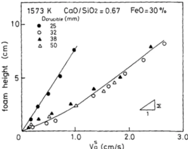
Ito and Fruehan8, found a relationship between supericial
gas velocity and slag height, which is in equation 5.
/
( )
H
V
g5
s
R
=
D
D
Where:
ΔH = Variation in slag height (cm); ΔVs
g = Variation of supericial gas velocity (cm/s).
As the height of the slag grew linearly with the supericial velocity (Figure 2), and Σ became constant after a certain supericial velocity was reached, they concluded that Σ could be used as a foaming index.
2.2.1. Mathematical models for the foaming index
Several models have been proposed by researchers to deine the foaming index using the physical properties of the slag.
Equation 6 includes the model of Ito and Fruehan8, which
did not consider the presence of solid particles and bubble size.
.
X
/
( )
5 7
10
26
n
ct
R
=
Where:
µ = viscosity (Pa.s); γ = surface tension (N.m-1);
ρ = liquid density (kg.m-3).
Figure 2: Relationship between slag height and supericial gas
velocity for several crucible diameters.
Jiang and Fruehan9 carried out a dimensional analysis
in order to ind the relationship between the physical properties. Thus, they found more speciic relationships (equations 7 and 8).
/
( )
:
Basic Slag
R
=
115
n
tc
7
.
/(
)
( )
:
Acidic Slag
0 93
28
3
n
t
c
R
=
However, according to Stadler10, these relationships
do not properly explain the foaming for acidic slag, either because of uncertainties associated with the measurement or prediction of slag properties.
In 1995, Zhang and Fruehan11 proposed new models that
considered the bubble diameter (Db) formed in the foaming.
:
( )
Basic Slag
115
.D.9
.
b 0 2 0 9
1 2
R
=
tcn
:
.
( )
Acidic Slag
10 3
X
10
D10
4 . ,
.
b 0 4 11 4 23
1 2
R
=
n tcFor basic slag, the viscosity had a greater weight on the foaming index, while for acidic slag the most inluential factor is surface tension.
In Ghag’s12 model (equation 11), viscosity was considered
to have a signiicant efect on the height of the slag, besides considering as well the efective elasticity of the liquid ilm that forms the bubble (Ef) and gravitational constant g.
( )
X
1
10
( )g D11
E 6
b ff 2 3
R
=
tnSkupien and Gaskell13 repeated the dimensional analysis
performed by Jiang and Fruehan9 for other surface tension
values, viscosities and densities, obtaining the following correlation:
( )
100
. .12
.
0 39 0 15 0 54
R
=
t cn
Kim et al.2, suggested models for the CaO-SiO 2
MnO, P2O5 and CaF2), showing the same parameters used in equation 7.
:
/
( )
Basic Slag
R
=
214
n
tc
13
:
/
( )
MgO
-
S
aturated Slag
R
=
999
n
tc
14
Note that although dependent on the same physical properties, if compared with equation 7, Kim’s model (equation 13) shows a large diference in the coeicient, which is due to diferences between the properties used in each analysis2.
All foaming index models are based on the physical properties of the slag: viscosity (μ), surface tension (γ) and slag density (ρ). However, some authors14 found no
relationship between foaming and slag properties, while others found no relationship between the experimental and theoretical results15.
It is important to draw attention to the presented models, as they were calculated for temperatures lower than the actual temperatures of the EAF Slag, around 1700°C, besides having considered that the steel and slag are at the same temperature, but it is known that in the reining step, the temperatures are diferent, whereas the slag has a higher temperature than the liquid steel 16.
2.3. Inluence of the viscosity
As the foamy slag depends on the rise of bubbles formed by the described reactions, it was found that slag viscosity is extremely important to efective foaming. The increase in viscosity decreases the drainage rate of the liquid foam, giving the bubble a longer residence time, increasing foam height and stability3.
The efective viscosity of the slag can be calculated (equation 12) considering the presence of solid particles.
(
1
1 35
.
)
/( )
15
e
5 2
h
=
h
-
i
-where:
ηe - efective viscosity of the slag (Pa.s)
η - viscosity of the molten slag (Pa.s) θ - fraction of precipitated solid phases
Figure 3 shows the efect that the viscosity has on the foaming index. An optimal slag is not completely liquid, whereas the presence of solid particles is crucial.
The solid particles act as nucleation sites for the bubbles, causing a large amount of small bubbles to be generated in the foamy slag6. Figure 3 shows that an increase in viscosity
provides an increase in the foaming index, reaching a peak where the optimal slag is found. However, an excessive increase in viscosity forms crusty slag and the presence of solid particles begins to be harmful, because bubble ascension is impaired.
Figure 3: Relationship between the foaming index and efective
viscosity.
Wu et al.17 demonstrated that for the obtained data, the
surface tension and density have very little dependence with the chemical composition and the viscosity decreases as the FeO content increases, which would cause an decrease in the foaming index, strongly varying with basicity and FeO content.
It is risky to use the foaming index as the only parameter in analysis of foamy slag. All models are directly proportional to viscosity, and inversely proportional to density and surface tension. It is known that the viscosity vary with composition, and as said before, it would be a good approximation to use a constant surface tension and density in the model calculation. Then very viscous slag would have a high value of foamy index. This may lead to errors, because very viscous slag can be harmful to the foaming.
2.4. Inluence of Basicity
Basicity has a strong inluence on the foaming, both in the cases of acidic slag and basic slag, because the basicity is directly related to slag viscosity (Figure 4).
Figure 4: Inluence of the %CaO/%SiO2 ratio on viscosity in a)
acidic slag and b) basic slag.
In acidic slag, increasing the CaO content causes a break in silica bonds causing a decrease in viscosity and, consequently, a decrease in the foaming index.
According to Morales et al.19, silica has surfactant properties in the steel slag, allowing solid particles to bind.
2.5. FeO Inluence
The FeO present in the slag, in addition to representing a decrease in the furnace yield, also causes an efect that can be deleterious to the slag due to its luxing characteristic, causing decreased viscosity.
Figure 5 shows the viscosity variation in a CaO-SiO2
-FeO ternary diagram. The isobasicity line (B2=1) shows that
when the same ratio of %CaO/%SiO2 is maintained, and the
FeO content is increased, there is a reduction in viscosity.
Figure 5: Viscosities of CaO-SiO2-FeO slag at 1823 K – calculated
by Urbain’s model. With an iso basicity line B2=1.
This shows that the FeO content is extremely important, since there is a balance between the FeO created by the injected O2 and the FeO reduced by the carbon; if this balance is correct, there will be good foaming.
Corbari20, studied how the slag behaved for diferent
FeO contents, with basicity B2 = 1.2, showing that for very
high or very low FeO contents, the slag height and stability were lower than those found for intermediate FeO values (between 25% and 30%). In these cases, the generated foam was still present after the gas generation decreased considerably (Figure 6).
Aminorroaya21 found that for basicity B
2=2.2, the highest
slag height occurred in FeO contents between 20% and 25%. It also showed that for FeO contents between 20%-25%, energy consumption was lower than that found when the FeO content was between 25%-30%.
Therefore, it can be said that there is an optimum FeO content for foaming, but it was diferent for the two cases shown, 25-30% for Corbari20 and 20-25% for Aminorraya21.
The data from these authors show the dependence on the chemical composition, due to the diference in basicity (respectively 1.2 and 2.2).
Figure 6: Relationship between slag height and time for diferent
FeO contents.
2.6. MgO Saturation
MgO saturation ensures not only the presence of solid particles (as in the case of CaO), but also that the consumption of the refractory is not excessive, as it prevents the slag from “stealing” MgO from the refractory.
To show the saturation levels, Pretorius6 developed
isothermal solubility diagrams (ISD), as shown in Figure 7. The double saturation point shows the ideal condition to protect the furnace refractories when in contact with the slag.
Figure 7: Generic Isothermal Saturation Diagram.
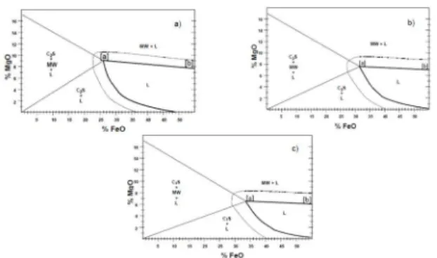
The ISDs show that the MgO saturation levels vary according to basicity and the FeO content (Figure 8). With the increase in basicity, the MgO levels required for saturation decrease. There is also a reduction in the variation of MgO saturation contents with the increase in FeO (line between points [a] and [b] in Figure 8).
Using the FactSage v.6.4 thermodynamic simulation software, Paulino22 made ISD’s with the same conditions
Concerning the lowers MgO values obtained by the software, Tayeb et al.24 analyzed FactSage’s ability to accurately predict
MgO saturation. Figure 10 compares the current data, illed triangles, to calculated values of FactSage, open circles. It is apparent that FactSage underestimates MgO solubility by up 2.5 wt pct,as compared to the measured data, especially at higher basicities, while showing reasonable agreement at lower basicities24.
Figure 8: Isothermal saturation diagrams for diferent basicities
(a) B3=2.0; (b) B3=2.5; (c) B3=3.0.
uses Gibbs energy minimization to calculate general phase diagram sections thermodynamically using the zero phase fraction line concept (ZPF). The program irst scans the edge of the diagram to ind the ends of the ZPF lines. Each line is then followed from beginning to end, using Gibbs energy minimization to determine the point at which a phase is just on the verge of being present23.
According to Paulino, the conditions for MgO saturation were the same for slag with low basicity (B2 < 2.0). For
higher basicity, the slope of the saturation line is positive, increasing the MgO saturation with the FeO contents, therefore the FeO efect in the MgO saturation line is the contrary to what was mentioned by Pretorius. Besides that, the MgO saturation and double saturation point values obtained by FactSage software were lower if compared to the values found previously.
Some of the diferences may possibly be attributed to the chosen database. As the “FToxid”, the main database considered, is composed by two databases: FToxid solution (FToxid53Soln.sda - contains oxide solutions); FToxid compound (FToxid53Base.cdb - contains all stoichiometric solid and liquid oxide compounds). However Paulino only used the solution model, rather than using compound solution model as well22.
The ISDs are a quick and practical way to analyze MgO saturation and the quality of slag foaming, but some issues need to be considered, such as the presence of other oxides, because they may have large inluence both on the liquid ield and the double saturation point.
2.7. Inluence of supericial gas velocity
For adequate foaming, the presence of CO bubbles is required; a high amount of bubbles together with good stability results in more eicient foaming. Supericial gas velocity is essential to obtain these results.
There are signiicant diferences in the behavior of the foam generated by high and low gas velocity. These foams are called expanded slag and foamy slag, respectively3.
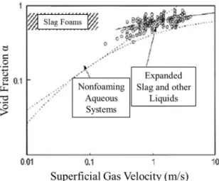
Figure 11 shows the “position” of the foamy slag and the expanded slag considering the fraction of gaps and supericial gas velocity. The fraction of gaps for both types of slag can be almost the same, making it easy to confuse the expanded slag with the foamy slag.
The main diferences between the foamy slag and expanded slag are25:
• Foamy slag: low supericial velocity; two distinct layers: a layer of foam over the layer of slag with few gaps; a large amount of bubbles, with thin walls, providing good stability, that is, the foam takes a long time to collapse even when gas generation decreases signiicantly.
• Expanded Slag: a uniform and mixed layer; the fraction of gaps varies according to the supericial gas
Figure 9: Isothermal saturation diagrams for diferent basicities
(a) B2=2.0; (b) B2=2.5; (c) B2=3.0.
Figure 10: MgO solubility predicted by Factsage, open circles, and
Figure 11: Summary of supericial gas velocity by fraction of gaps
for foaming and non-foaming systems.
velocity (Figure 10); a turbulent appearance; large gaps with thick walls separating them, causing low stability, that is, when the gas generation decreases, the height of the slag starts to decrease considerably. Zhu et al.3 concluded that as the supericial gas velocity
increases, the slag height increase rate decreases dramatically. This occurs when the amount of slag that has still not foamed is consumed, causing a change in the mechanism causing a less stable foam.
Barella et al.26 stated that decrease in the height of the
foam at high supericial gas velocity is associated with the increase of bubbles created in the gas difuser. However, in industrial tests, the foam did not collapse at higher supericial velocities, since the bubbling process, under industrial conditions, led to the formation of ine bubbles that are not suitable for draining.
2.8. Inluence of the bubble size
Another parameter that inluences slag foaming is the bubble size. It is known that ine bubble generate better quality foaming than the foam generated by large bubbles26. This
is because the ine bubbles generate spherical cells that are more stable, whereas the large bubbles generate polyhedral cells, which have reduced stability11.
The bubble size sufers inluence of several factors, such as surfactant elements, supericial gas velocity and gas forming reactions.
Although there is disagreement among authors about the reaction that produces the inest bubbles and thus better foaming (section 2.1), it is clear the need for further study to better understand the creation of bubbles by the reactions shown in equations 1 to 3.
According to Zhang 11, the size of bubbles generated
in the metal/slag interface depends on the activity of the surfactant element in the bath. This is because the bubble size
is determined by the ratio between the thrust and interfacial tension, depending on the contact angle. Surfactant elements, such as sulfur, increase this angle, resulting in larger bubbles and less stable foaming.
A high supericial gas velocity is associated with larger bubbles, and with this, less stable foaming. This is because large bubbles favor the drainage of the luid ilm, which reduces bubble stability26.
Some authors who tested diferent mathematical models, found no statistical evidence to justify the use of bubble size and the surface tension depression in place of the surface tension as a predictor of foaming10. But as stated
before some authors found that foamy index was inversely proportional to the average bubble diameter11 or to the cube
of the bubble diameter12.
3. Conclusions
Knowledge of the steel-making process is of utmost importance to understand the foamy slag phenomenon.
It is necessary to optimize several parameters so that slag foaming can have the best performance possible:
• A good amount of carbon and oxygen available so that the reactions that generate CO can occur, producing a large amount of bubbles;
• Slag saturation (%CaO and %MgO) for high viscosity, with solid particles that nucleate CO bubbles; • Optimal FeO content of the slag;
• Low supericial gas velocity, preventing the slag from becoming expanded slag.
Since it is a complex practice, the slag foaming phenomenon can still be extensively explored and developed by researchers in order to improve the steelmaking process in the steel industry.
4. References
1. Avila TA. Condicionamento de escórias em forno elétrico a arco para otimização das condições de espumação da escória e reino do aço. [Dissertation]. Belo Horizonte: Universidade Federal de Minas Gerais; 2011.
2. Kim HS, Min DJ, Park JH. Foaming behavior of CaO–SiO2–
FeO–MgOsatd–X (X=Al2O3, MnO, P2O5, and CaF2) slags at high
temperatures. ISIJ International. 2001;41(4):317-324.
3. Zhu TX, Coley KS, Irons GA. Progress in Slag Foaming in Metallurgical Processes. Metallurgical and Materials Transactions B. 2012;43(4):751-757.
4. Kozhuhov AA, Fedina VV, Merker EE. Study of the foaming of steelmaking slag and its efect on the thermal performance of an electric-arc furnace. Metallurgist. 2012;56(3):169-172.
5. Novak M, Straka J, Pribyl M. Inluence of the Slag Foaming Process Applied in High Alloyed Steel Production on Refractory Wear of EAF at Pilsen Steel Melt Shop. In: Proceedings of 11th Biennial Worldwide Conference on Uniied International Technical Conference Refractories 2009 (UNITECR 2009);
6. Pretorius EB, Carlisle RC. Foamy slag fundamentals and their practical application to electric furnace steelmaking. In:
Proceedings of the 16th Process Technology Conference; 1998
Nov 15-18; New Orleans, LA, USA.
7. Matsuura H, Fruehan RJ. Slag Foaming in an Electric Arc Furnace. ISIJ International. 2009;49(10):1530-1535.
8. Ito K, Fruehan RJ. Study on the foaming of CaO-SiO2-FeO
slags: Part I. Foaming parameters and experimental results.
Metallurgical Transactions B. 1989;20(4):509-514.
9. Jiang R, Fruehan RJ. Slag foaming in bath smelting. Metallurgical Transactions B. 1991;22(4):481-489.
10. Stadler SAC, Eksteen JJ, Aldrich C. An experimental investigation of foaming in acidic, high FexO slags. Minerals Engineering.
2007;20(12):1121-1128.
11. Zhang Y, Fruehan RJ. Efect of the bubble size and chemical reactions on slag foaming. Metallurgical and Materials Transactions B. 1995;26(4):803-812.
12. Ghag SS, Hayes PC, Lee HG. The Prediction of Gas Residence Times in Foaming CaO-SiO2-FeO Slags. ISIJ International.
1998;38(11):1216-1224.
13. Skupien D, Gaskell DR. The surface tensions and foaming behavior of melts in the system CaO-FeO-SiO2. Metallurgical and Materials Transactions B. 2000;31(5):921-925.
14. Hong L, Hirasawa M, Sano M. Behavior of Slag Foaming with Reduction of Iron Oxide in Molten Slags by Graphite.
ISIJ International. 1998;38(12):1339-1345.
15. Lotun D, Pilon L. Physical Modeling of Slag Foaming for Various Operating Conditions and Slag Compositions. ISIJ International. 2005;45(6):835-840.
16. Turkdogan ET, Fruehan RJ. Fundamentals of Iron and Steelmaking. In: The AISE Steel Foundation. The Making, Shaping and Treating of Steel. Vol 2: Steelmaking and Reining Volume. Pittsburg: The AISE Steel Foundation; 1998.
17. Wu LS, Albersson GJ, Sichen D. Modelling of slag foaming.
Ironmaking & Steelmaking. 2010;37(8):612-619.
18. Coudurier L, Hopkins DW, Wilkomirsky I. Fundamentals of Metallurgical Processes. Oxford: Pergamon Press; 1978.
19. Morales RD, Rodríguez-Hernandez H, Garnica-Gonzalez P, Romero-Serrano JA. A Mathematical Model for the Reduction Kinetics of Iron Oxide in Electric Furnace Slags by Graphite Injection. ISIJ International. 1997;37(11):1072-1080.
20. Corbari R, Matsuura H, Halder S, Walker M, Fruehan RJ. Foaming and the Rate of the Carbon-Iron Oxide Reaction in Slag.
Metallurgical and Materials Transactions B.
2009;40(6):940-948.
21. Aminorroaya-Yamini S, Edris H. The Efect of Foamy Slag in the Electric Arc Furnaces on Electric Energy Consumption. In:
Proceedings of the 7th European Electric Steelmaking Conference;
2002 May 26-29; Venice, Italy. p. 2447-2456.
22. Paulino MAS, Klug JL, Bielefeldt WV, Vilela ACF, Heck NC. Obtenção de escória espumante em forno elétrico a arco: determinação das composições para o sistema CaO-SiO2
-MgO-FeO. In: Proceedings of the 45° Steelmaking Seminar – International; 2014 May 25-28; Porto Alegre, RS, Brazil.
23. Peltron AD. Thermodynamics and phase diagrams of materials. In: Korstorz G, ed. Phase transformations in Materials. New York: Wiley-VCH; 2001.
24. Tayeb MA, Assis AN, Sridhar S, Fruehan RJ. MgO Solubility in Steelmaking Slags. Metallurgical and Materials Transactions B. 2015;46(3):1112-1114.
25. Gou H, Irons GA, Lu WK. A multiphase luid mechanics approach to gas holdup in bath smelting processes. Metallurgical and Materials Transactions B. 1996;27(2):195-201.
26. Barella S, Gruttadauria A, Mapelli C, Mombelli D. Critical evaluation of role of viscosity and gas lowrate on sag foaming.