Analysis of Composite Membranes in the Separation of Emulsions Sunlower oil/water
Dionisio da Silva Birona, Mara Zenia, Carlos Pérez Bergmannb, Venina dos Santosa*
Received: September 27, 2016; Revised: February 05, 2017; Accepted: April 09, 2017
Oil is a major pollutant of water resources, afects aquatic life, causing environmental degradation. Currently there is an increase in studies of membrane applied to separation of oil-water. Among these
membranes, there are composite membranes, which show as main characteristic an association of
organic and inorganic membrane properties. In a tangential low process, the ceramic tube (support) is responsible for the mechanical strength of the membrane and the selective barrier property of the membrane is established by the polymer. The aim of this work is the application of α-alumina/ polyamide 66 composite membrane in the retention of sunlower oil from oil-water emulsions and the study of resistance of such membranes in ultrailtration processes. The α-alumina ceramic tubes were impregnated internally with a solution of polyamide 66 (PA66) (5% w/v) and tested with distilled water and sunlower oil solutions at concentrations of 50, 100 and 200 mg∙L-1. Membranes impregnated with PA66 showed a sunlower oil retention between 53.5 and 99.5% and superior membrane resistance (MR) to the permeate lux (1.92 x 10¹³ a 5.52 x 10¹³) which explains the decrease in the permeate volume.
Keywords: Separation, Composite membranes, Ultrailtration, Sunlower oil
* e-mail: [email protected]
1. Introduction
Oil is a water insoluble substance, derived from petroleum,
mineral, plant and animal sources. This component has been used in industry, throughout the history, for example, as a lubricant in metalworking, becoming indispensable in industry
processes1,2. As a result of these processes, a signiicant amount of oil has been generated in the form of emulsions
of oil in water or water in oil for petrochemical industries, transport and metal-mechanics industries3.
Currently studies have sought alternatives to replace oil derived from non-renewable sources, the use of vegetable oils in an important one. These materials can not only substitute
mineral oil, but also provide a renewable character2-4. Oil is a major pollutant of water resources, afects aquatic life, causing environmental degradation. Generally, a stable oil-water emulsion shows oil droplets of a size up to 20 µm.
Even with the presence of oil-water interface, the oil phase
cannot be separated by simple gravity, a most appropriate treatment process is required4-5.
Several technologies have been developed in the demulsiication of oil-water solutions. The centrifugal separation, chemical sedimentation, lotation and membrane separation processes are used for oil removal. To increase the quality of these processes, the study of membranes for the retention of oil plays an important role. Transmembrane pressure is a driving force for this technology, which
forces the passage of emulsiied liquid by a porous system (membrane), performing the retention of oil on the surface
of the material6-7. Membrane technology has advantages as lower space required, low cost and possibility to separate streams with low concentrations, reaching high eiciencies (90-99%). Typically, the oil concentration in the feed varies from 50 to 1000 mg∙L-1, and the inal concentration after the process of 10-15 mg∙L-1 is desired8-12.
The use of membranes provides numerous advantages, however a diiculty to the continuity of the permeate lux
is observed in membrane processes, as in any other real
physical process where there are moving between distinct parties. The main constraints to the permeate lux are: concentration polarization, polarized layer and fouling. For a process using membranes, to know and to control these characteristics are essential for the viability of the process.
However, physical processes such as mechanical removal
or backwashing, and chemical methods such as the use of acidic or alkaline solutions are needed to recover the permeate lux, partially or totally13-15.
Several studies have demonstrated the efectiveness of using ultrailtration membranes with tangential lux in oil separation processes, which provide satisfactory results. Membranes for demulsiication are compact modules and can work continuously16-18. The aim of this study is to obtain a composite ilter system with greater selectivity, composed of an inorganic and organic material (α-alumina/PA66). The
polymeric layer is responsible for the selectivity, and the ceramic a Exact Sciences and Technology Centre - CCET, University of Caxias do Sul - UCS, 95070-560,
Caxias do Sul, RS, Brazil
b Laboratory of Ceramic Materials, School of Engineering, Federal University of Rio Grande do Sul -
support allowed the necessary support to the polymer ilm19,
and also to emphasize the study of membrane resistance by
the retention of sunlower oil of the oil-water solutions. In the experiments of oil-water were used oil concentrations of 50, 100 and 200 mg∙L-1, and transmembrane pressures of 150, 200, 250 and 300 kPa.
It is important to highlight that the composite membranes with a layer of polyamide 66 (PA-1) and with two layers of polyamide 66 (PA-2) and the ceramic support were
characterized in previous study20.
2. Experimental
2.1. Preparation of the composite membrane
The membrane was prepared by dip-coating from polyamide 66 solution (PA66) (RhodiaTechnyl) inside the tubular ceramic support (pore diameter of 0.65 μm) (Tecnicer-Celebra, São Carlos - Brazil). The PA66 solution was prepared at a concentration of 5% (w/v) using formic acid (HCOOH) (Vetec) as solvent. The deposition of the
polymeric solution was carried in the inner part the ceramic
tube. The ceramic tube was closed on one side and the solution kept in the tube for two hours. Excess solution was removed, and the tube immersed in distilled water for 30 min in order to form the selective layer of PA66 by reverse
phase process20. The composite membrane remained for 6 h at 30 ºC in a vacuum oven to remove the excess solvent. The process was repeated to perform the deposition of the second layer of PA66.
2.2. Tangential ultrailtration system
The separations of oil-water emulsions were made into a bench ultrailtration system, as shown in Figure 1. All microiltration tests in this work were performed at a feed temperature of 20 ± 2ºC. The system comprises a feed tank of 3 L, pumping system with a diaphragm pump with 3 chambers from Positive Displacement and motor from Permanent Magnet P/N 11-155-05. The working lux used was 0.93 L.min-1 with theoretical Reynolds number, calculated, of 2,630.
2.3. Membrane characterization with distilled water
The commercial ceramic support and the composite membrane were characterized by distilled water lux at pressures of 150, 200, 250 and 300 kPa and calculated according to Eq. (1). Each experiment was performed by 120 min and pressure changes occurred during this process, i.e. a diferent pressure was used for 30 min over the course of the experiment. The purpose of this procedure was to
determine the maximum transmembrane lux (membrane performance), and to calculate the resistance before any modiication in the porous layer, as an obstruction of the membrane pores by oil droplets, for instance.
Figure 1. System used in the process of microiltration.
.
( )
J
wA t
V
1
D
=
Where Jw is the permeate lux to distilled water (L∙m-2∙h-1), V is the volume of permeate (L), A is the useful membrane area (m²) and Δt is the permeation time (h).
2.4. Permeate lux of oil and water and
determination of oil rejection
The permeate low of oil and water was obtained at pressures of 150, 200, 250 and 300 kPa. The oil concentrations of the solutions were 50, 100 and 200 mg∙L-1. For the preparation of the oil/water emulsions was used distilled water and commercial sunlower oil. The emulsion was prepared by mechanically stirring for 10 minutes to 10,000 rpm22. The mechanical stirring resulted an oil droplet size of approximately 12.1 ± 5 µm. Eq. (1) was used to calculate the permeate lux. Oil retention was measured using a spectrophotometer (GENESYS 10 UV Ultraviolet Spectrophotometer, Thermo Spectronic UV-visible) wavelength in 210 nm. Eq. (2) was
used to calculate rejection:
%
OR
=
T
1
-
Cp
Cf
Y
( )
2
Where %OR is the oil retention, Cp is the permeate oil concentration and Cf is the feed oil concentration.
2.5. Membrane Resistance (MR)
Permeate lux, with distilled water, was used to calculate the resistance of the membrane in a free change membrane, the value was obtained from Eq. (3).
in the beginning of the process than support. One can see a close agreement between the permeate lux of PA-1 and PA-2, especially in the pure water test, Figure 2 (a), demonstrating a possible ineiciency in impregnation of the irst polymer layer or even the second layer, since they showed similar results.
The decrease in permeate lux presented by the ceramic
tube and the membrane is due to the increased concentration
of oil in the emulsion, forming a cake layer, which rapidly blocks the passage of the permeate lux17-23. The membrane
was cleaned with a solution containing distilled water and neutral detergent. The neutral detergent concentration was 2% (v/v).
3.2. Oil-water lux and oil rejection
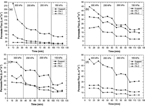
Figure 3 shows the results of oil-water permeate lux for the membranes.
A more signiicant decrease in the permeate lux of support in relation to PA-1 and PA-2 can be observed. This shows a more signiicant increase of oil on the surface of the ceramic support, causing the reduction on permeate lux13,15,17.
The oil retention of membranes is shown in Figure 4. The support showed lower values than PA-1 and PA-2, around 43.3 and 92.3%. The PA-1 showed values around 53.8 and 97.7%, while PA-2 showed values around 96%, reaching an eiciency of 99.5%. The minimum and maximum values,
presented previously, obtained from the composite membranes
and the ceramic support, can be veriied in sunlower oil concentration of 50 mg∙L-1 with applied pressure of 300 kPa and in sunlower oil concentration of 200 mg∙L-1 with applied pressure of 150 kPa, respectively.
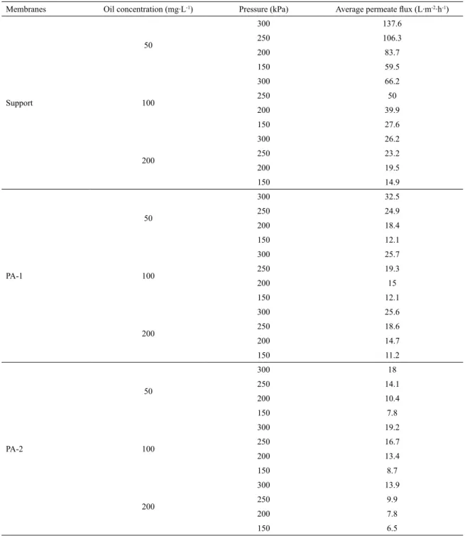
Table 1 shows the comparative result of the permeate lux obtained by the ceramic support and the PA-1 and PA-2 membranes. When we analyze the Table 1, we observe that in concentration of 50 mg∙L-1 of sunlower oil with transmembrane pressure of 300 kPa the average permeate lux was 137.6 L∙m-2∙h-1 for the ceramic support and 32.5 L∙m-2∙h-1 for the PA-1 membrane, which corresponds to 76.4% more of permeate lux for the ceramic support. Under the same conditions, we veriied that the ceramic support presents 86.9% more of permeate lux in relation to PA-2 membrane. That diference in permeate lux between PA-1 and PA-2 is due to larger coating of the pores of ceramic
support by the polymeric layer, and it occurred more in
the membrane with two layers of PA6620. In the operation conditions of 200 mg∙L-1 of sunlower oil concentration and transmembrane pressure of 150 kPa we see a reduction of this diference. The average permeate lux for the ceramic support, in the conditions presented, in relation to PA-1 and PA-2 membranes, was around 24.8% and 56.4% more, respectively. That approximation may be related to the hydrophilic character presented by PA66, which repels the oil droplets.
.
( )
MR
n J
P
3
w w
D
=
Where ΔP is the variation in pressure (kPa), nw is the dynamic viscosity of the liquid and MR is the resistance of the membrane.
2.6. Fouling Resistance (FR)
The fouling resistance is obtained after ultrailtration process when distilled water pass through a membrane, it means, when permeate lux loss occurs due to oil droplets which were adhered to the membrane surface. Eq. (4) was used to determine the fouling resistance.
.
( )
FR
n J
P
MR
4
w w
D
=
-Where nw regards the properties of the oil-water solution
and FR is the fouling resistance.
2.7. Resistance to polarization (RP)
The concentration polarization occurs when the solids are
entrained to the membrane surface by convective transport and partially or totally rejected, the solids tend to concentrate
on the interface, forming a concentration gradient. Eq. (5) was used to calculate the polarization resistance.
( )
RP
=
TR
-
MR
-
FR
5
Where RP is the polarization resistance and TR is the total resistance of the membrane, i.e. the resistance that occurs during the ultrailtration.
Eq. (1) was used to determine total membrane resistance, where the properties of the liquid employed were the oil-water solution.
3. Results and Discussion
3.1. Pure water Flux
Figure 2 shows the results of permeate lux for ceramic tube (support) and for membrane with one and two layers of polyamide 66 (PA-1 and PA-2, respectively).
Support showed higher permeate lux in all iltrations, but decreased signiicantly throughout the tests in relation to PA-1 and PA-2. Initially support lux was 300 L∙m-2∙h-1 at a pressure of 300 kPa, the permeate lux in the last test showed a recovery from 42 to 73 L∙m-2∙h-1. The permeate water lux, in a pressure of 150 kPa, was around 31 L∙m-2∙h-1.
Figure 2. Water lux tests (a) starting with pure water, (b) after the ultrailtration with oil concentration of 50
mg∙L-1, (c) after ultrailtration test with oil concentration of 100 mg∙L-1 and (d) after the ultrailtration with oil
concentration of 200 mg∙L-1.
Figure 3. Oil-water lux for oil concentrations of (a) 50 mg∙L-1, (b) 100 mg∙L-1 and (c) 200 mg∙L-1.
When we compared the PA-1 and PA-2 membranes, we observed that, at the concentration of 50 mg∙L-1 of sunlower oil and 300 kPa applied pressure, the lux was 44.6% more for the PA-1 membrane. The same occurs in the concentration of
Figure 4. Results for oil rejection in the following pressures (a) 300 kPa, (b) 250 kPa, (c) 200 kPa and (d) 150 kPa.
The signiicantly better oil retention in PA-1 and PA-2 is due to the use of polymeric skin in order to provide superior oil separation, increasing retention, but also showed a signiicant decrease in permeate lux (Figure 2)24. The retention capacity
of the composite membranes can be understood due to
two mechanisms: 1) the skin formed on the surface of the porous material has lower porosity and prevents the passage of the oil droplets and 2) the deposited polymeric skin has hydrophilic properties and this skin shows aversion to oil.
3.3. Membrane Resistance (MR)
Membrane resistance values at diferent pressure are shown in Figure 5. PA-2 showed greater resistance to the passage of water, due the thickness of the polymer layer impregnated on the support. Support showed the lowest
resistance, due to the fact that the support does not present
any additional resistance to permeate low, because there
is not the polymeric layer, which increases the resistance
of the membrane.
PA-2 membrane showed an increase in resistance with the increase in pressure, but on the other hand, the PA-1 and
support membranes showed a decrease in resistance with
the increase in pressure. Increase in membrane resistance is imminent from two layers of polymer, it also explains the lower lux of the PA-217. The increase of the membrane
Figure 5. Membranes resistance analysis by pressure.
resistance for PA-2 occurs due to a greater surface coating
of the pores of the ceramic support, as can be seen in the
SEM, Figure 4 (e), obtained in the previous paper20.
3.4. Fouling Resistance (FR)
Table 1. Result of average values of the permeate lux to the ceramic support and to the PA-1 and PA-2 membranes.
Membranes Oil concentration (mg∙L-1) Pressure (kPa) Average permeate lux (L∙m-2∙h-1)
Support
50
300 137.6
250 106.3
200 83.7
150 59.5
100
300 66.2
250 50
200 39.9
150 27.6
200
300 26.2
250 23.2
200 19.5
150 14.9
PA-1
50
300 32.5
250 24.9
200 18.4
150 12.1
100
300 25.7
250 19.3
200 15
150 12.1
200
300 25.6
250 18.6
200 14.7
150 11.2
PA-2
50
300 18
250 14.1
200 10.4
150 7.8
100
300 19.2
250 16.7
200 13.4
150 8.7
200
300 13.9
250 9.9
200 7.8
150 6.5
The fouling resistance of PA-1 was increased by the applied pressure, Figure 6, because for greater pressures there is a stronger compression of solute on the surface causing increased low obstruction25,26. Moreover, the increased pressure in the test with PA-2 resistance decreases, showing
that the application of pressure ruptures the resistance
exerted by fouling.
3.5. Total Resistance (TR)
Total resistance values for the membranes are shown in Figure 7 as a function of transmembrane pressure. It was not observed signiicant diference between the applied pressures, however, the increase of the polyamide layers inluenced
in the increase of the total membrane resistance, which
Figure 6. Analysis of fouling resistance of membranes by pressure. (a) Support, (b) PA-1 and (c) PA-2.
Figure 7. Analysis of the total resistance of membranes by pressure. (a) Support, (b) PA-1 and (c) PA-2.
3.6. Resistance to polarization (RP)
The polarization resistance according to the transmembrane pressure can be seen in Figure 8. A decrease in resistance in PA-2 for both tests can be observed, the increased pressure
neither created a polarized layer nor increased the polarization
layer. Diferently, support and PA-1 have maintained their resistance throughout the tests27.
Figure 8. Analysis of the polarization resistance of membranes by pressure. (a) Support, (b) PA-1 and (c) PA-2.
Table 2. Percentage contribution of each type of obstruction with oil concentration of 50 mg∙L-1.
Membrane Pressure (kDa) TR (m-1) x 1013 MR(%) FR(%) RP(%)
Support
300 0.78 67% 33% 0%
250 0.84 95% 5% 0%
200 0.86 100% 0% 0%
150 0.91 97% 3% 0%
PA-1
300 3.31 59% 41% 0%
250 3.60 86% 10% 4%
200 3.90 93% 0% 7%
150 4.46 86% 0% 14%
PA-2
300 5.98 92% 0% 8%
250 6.36 85% 7% 7%
200 6.90 78% 20% 2%
150 6.90 78% 22% 0%
Table 3. Percentage contribution of each type of obstruction with oil concentration of 100 mg∙L-1.
Membrane Pressure (kDa) TR (m-1) x 1013 MR(%) FR(%) RP(%)
Support
300 4.11 13% 53% 34%
250 3.86 21% 52% 27%
200 3.68 24% 51% 25%
150 3.62 24% 69% 7%
PA-1
300 4.20 46% 54% 0%
250 4.64 55% 45% 0%
200 4.77 66% 34% 0%
150 4.46 74% 26% 0%
PA-2
300 5.60 91% 9% 0%
250 5.37 94% 6% 0%
200 5.37 81% 19% 0%
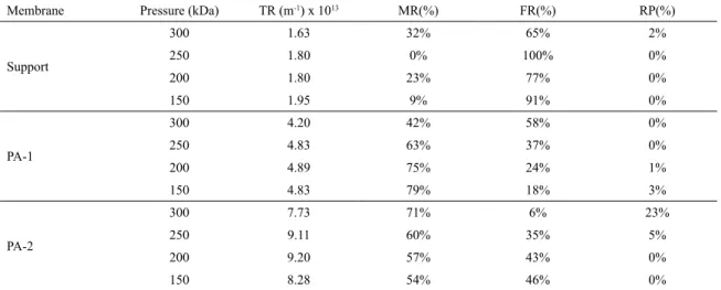
Table 4. Percentage contribution of each type of obstruction with oil concentration of 200 mg∙L-1.
Membrane Pressure (kDa) TR (m-1) x 1013 MR(%) FR(%) RP(%)
Support
300 1.63 32% 65% 2%
250 1.80 0% 100% 0%
200 1.80 23% 77% 0%
150 1.95 9% 91% 0%
PA-1
300 4.20 42% 58% 0%
250 4.83 63% 37% 0%
200 4.89 75% 24% 1%
150 4.83 79% 18% 3%
PA-2
300 7.73 71% 6% 23%
250 9.11 60% 35% 5%
200 9.20 57% 43% 0%
150 8.28 54% 46% 0%
RM and RF. However, these data may be analyzed as near zero,
indicating that there was virtually no resistance to low caused
by concentration by polarization and the polarized layer27.
3.7. Resistance contribution
Tables 2, 3 and 4 show the percentage contribution caused by the permeate lux for each type of obstruction, membrane, fouling and polarization, for oil concentration
of 50, 100 and 200 mg∙L-1. The fouling membrane was 65 at 100% for the test performed at 200 mg∙L-1 for support,
due the diameter of the oil droplets, which penetrate the
pores causing fouling15. In experiments the contribution of membrane resistance varies in a wide range of 0 to 100% and fouling resistance from 0 to 100% and polarization resistance from 0 to 34%.
The foulingresistance is most signiicant in support, justifying for its permeate lux reduction during the tests26.
The polarized layer and concentration by polarization proved several time contributions of 0%, with a variation from 0 to 27%, for membranes studied. The largest contribution is the membrane resistance and foulingresistance, explaining the decrease of lux in the initial phase of the tests17.
4. Conclusion
The use of composite membrane is efective in removing
oil from oil-water solutions in the concentrations tested,
according to the results. However, the permeate lux had a signiicant decreasing because of the presence of PA66 layer on the inner surface of the support. Ceramic support retained the oil in a range of 43.3 to 92.3%, while the membranes of
one and two layers of polyamide 66 showed an oil rejection
of 53.8 to 97.7%, and 78.5% to 99.5%, respectively. The membrane resistance showed a signiicant contribution on total resistance, ranging between 0 and 100%, followed by fouling resistance ranging between 0 and 100% and the
polarized layer and concentration polarization (0 to 34%). Therefore, the application of these membranes under the
operational point of view proves to be feasible, since the
process ensures higher quality of the inal eluent. However, a larger area is necessary due to reduction in transmembrane lux when a selective layer of polyamide 66 is employed.
5. Acknowledgments
The authors would like to acknowledge the CNPq, CAPES for inancial support.
6. References
1. John J, Bhattacharya M, Raynor PC. Emulsions containing vegetable oils for cutting luid application. Colloids and Surfaces A: Physicochemical and Engineering Aspects. 2004;237(1-3):141-150. DOI: 10.1016/j.colsurfa.2003.12.029
2. Graboski MS, McCormick RL. Combustion of fat and vegetable oil derived fuels in diesel engines. Progress in Energy and Combustion Science. 1998;24(2):125-164. DOI: 10.1016/ S0360-1285(97)00034-8
3. Chen W, Peng J, Su Y, Zheng L, Wang L, Jiang Z. Separation of oil/water emulsion using Pluronic F127 modiied polyethersulfone ultrailtration membranes. Separation and Puriication Technology. 2009;66(3):591-597. DOI: 10.1016/j.seppur.2009.01.009
4. Abadi SRH, Sebzari MR, Hemati M, Rekabdar F, Mohammadi T. Ceramic membrane performance in microiltration of oily wastewater. Desalination. 2011;265(1-3):222-228. DOI:
10.1016/j.desal.2010.07.055
5. Chang Q, Zhou J, Wang Y, Liang J, Zhang X, Cerneaux S, et al. Application of ceramic microiltration membrane modiied by nano TiO2 coating in separation of a stable oil-in-water
emulsion. Journal of Membrane Science. 2014;456:128-133. DOI: 10.1016/j.memsci.2014.01.029
7. van der Sman RGM, Vollebregt HM, Mepschen A, Noordman TR. Review of hypotheses for fouling during beer clariication using membranes. Journal of Membrane Science. 2012;396:22-31. DOI: 10.1016/j.memsci.2011.12.051
8. Ebrahimi M, Willershausen D, Ashaghi KS, Engel L, Placido L, Mund P, et al. Investigations on the use of diferent ceramic membranes for eicient oil-ield produced water treatment. Desalination. 2010;250(3):991-996. DOI: 10.1016/j.
desal.2009.09.088
9. Emani S, Uppalurin R, Purkaitnn MK. Microiltration of oil-water emulsions using low cost ceramic membranes prepared with the uniaxial dry compaction method. Ceramics International.
2014;40(1 Pt A):1155-1164. DOI: 10.1016/j.ceramint.2013.06.117
10. Kukizaki M, Goto M. Demulsiication of water-in-oil emulsions by permeation through Shirasu-porous-glass (SPG) membranes. Journal of Membrane Science. 2008;322(1):196-203. DOI: 10.1016/j.memsci.2008.05.029
11. Kang W, Guo L, Fan H, Meng L, Li Y. Flocculation, coalescence and migration of dispersed phase droplets and oil-water separation in heavy oil emulsion. Journal of Petroleum
Science and Engineering. 2012;81:177-181. DOI: 10.1016/j.
petrol.2011.12.011
12. Böddeker KW. Liquid Separations with Membranes: An Introduction to Barrier Interference. Berlin: Springer; 2008. 13. Su TJ, Lu JR, Cui ZF, Thomas RK. Fouling of ceramic
membranes by albumins under dynamic iltration conditions. Journal of Membrane Science. 2000;173(2):167-178. DOI: 10.1016/S0376-7388(00)00370-7
14. Boributh S, Chanachai A, Jiraratananon R. Modiication of PVDF membrane by chitosan solution for reducing protein fouling. Journal of Membrane Science. 2009;342(1-2):97-104. DOI: 10.1016/j.memsci.2009.06.022
15. Colle RD, Longo E, Fontes SR. Demulsiication of water/sunlower oil emulsions by a tangential iltration process using chemically impregnated ceramic tubes. Journal of Membrane Science. 2007;289(1-2):58-66. DOI: 10.1016/j.memsci.2006.11.048
16. Fontes SR, Queiroz VMS, Longo E, Antunes MV. Tubular microporous alumina structure for demulsifying vegetable oil/ water emulsions and concentrating macromolecular suspensions.
Separation and Puriication Technology. 2005;44(3):235-241. DOI: 10.1016/j.seppur.2005.02.001
17. Mohammadi T, Pak A, Karbassian M, Golshan M. Efect of operating conditions on microiltration of an oil-water emulsion by a kaolin membrane. Desalination. 2004;168:201-205. DOI:
10.1016/j.desal.2004.06.188
18. Fang J, Qin G, Wei W, Zhao X, Jiang L. Elaboration of new ceramic membrane from spherical ly ash for microiltration of rigid particle suspension and oil-in-water emulsion. Desalination.
2013;311:113-126. DOI: 10.1016/j.desal.2012.11.008
19. Scott K. Handbook of Industrial Membranes. 1st ed. Oxford:
Elsevier Advanced Technology; 1995.
20. Biron DS, Poleto P, Duarte J, Zeni M, Bergmann CP, Santos V. Preparation and Characterization of PA66/Alumina Composite Membrane. Materials Research. 2015;18(4):748-755. DOI: 10.1590/1516-1439.004715
21. Mulder M. Basic Principles of Membrane Technology. 2nd ed.
Dordrecht: Kluwer Academic Publishers; 1996.
22. Sun D, Duan X, Li W, Zho D. Demulsiication of water-in-oil emulsion by using porous glass membrane. Journal of
Membrane Science. 1998;146(1):65-72. DOI:
10.1016/S0376-7388(98)00096-9
23. Machado RMD, Haneda RN, Trevisan BP, Fontes SR. Efect of enzymatic treatment on the cross-low microiltration of açaí pulp: Analysis of the fouling and recovery of phytochemicals. Journal of Food Engineering. 2012;113(3):442-452. DOI: 10.1016/j.jfoodeng.2012.06.022
24. Wei W, Xia S, Liu G, Gu X, Jin W, Xu N. Interfacial adhesion
between polymer separation layer and ceramic support for
composite membrane. Materials, Interfaces and Eletrochemical
Phenomena. 2010;56(6):1584-1592. DOI: 10.1002/aic.12086
25. Cheryan M. Ultrailtration and Microiltration Handbook. 2nd
ed. Boca Raton: CRC Press; 1998. 552 p.
26. Zeman LJ, Zydney AL. Microiltration and Ultrailtration: Principles and applications. New York: Marcel Dekker; 1996. 27. Nieuwenhuijzen AV, Van der Graaf J, eds. Handbook on Particle