Nano-modified Adhesive by Graphene: The Single Lap-Joint Case
Almir Silva Netoa, Diego Thadeu Lopes da Cruza, Antonio Ferreira Ávilab*
aGraduate Studies Program in Mechanical Engineering, Federal University of Minas Gerais – UFMG,
Av. Antonio Carlos, 6627, CEP 31270-901, Belo Horizonte, MG, Brazil
bGraduate Studies Program in Mechanical Engineering, Deparment of Mechanical Engineering,
Federal University of Minas Gerais – UFMG, Av. Antonio Carlos, 6627, CEP 31270-901, Belo Horizonte, MG, Brazil
Received: October 25, 2012; Revised: November 22, 2012
This paper addresses the performance study on, low viscosity, nano-modified adhesives by graphene. For achieving this goal, single-lap joints following ASTM D 5868-01 were manufactured and tested. X-ray diffraction, scanning electron microscopy and nanoindentation were employed for graphene based nanostructures characterization. The increase on joint strength was around 57% when compared against the control group. Furthermore, all failures for the nano-modified adhesive were cohesive failure for the carbon fibre/epoxy composites indicating that the adhesive was tested. X-ray diffractions signatures indicate formation of nano-structures with 17-19 nm diameters. Moreover, nanoindentation tests revealed a homogeneous dispersion of graphene.
Keywords: nanocomposites, graphene nanosheets, single-lap joints, nanomodified adhesives
1. Introduction
In many practical applications, it is virtually impossible to create structures in a single piece due to the high costs involved or geometrical limitations. The solution is the manufacturing of small parts that can be assembled together later on and it requires the use of joints. According to Tong and Steven1 the joint manufacturing process can be divided into welded, bolted/riveted and bonded. The assembly process of multi-parts composites structures typically applies the concept of bolted and/or bonded joints. The first one induces stress concentrations by the holes2 that can lead to premature joint’s failure3, while the second one is highly dependent on bonded area and adhesive strength. Tsai and Morton4 stated that the most commonly used adhesive bonded design is the single-lap joint due to its combined simplicity and efficiency. Furthermore, according to Banea and Da Silva5 with the increase interest on light weight structures, in special made of composite materials, the bonded joints technology becomes more diversified and more attractive to ordinary life applications.
In order to increase the adhesive load capacity, one idea is to change the joint’s design. Many new designs have been proposed by different research groups. Among those researchers are Zeng and Sun6, Avila and Bueno7 which designed a single wavy lap joint. This design allows a more efficient peel and shear stress distribution leading to higher load capacity. In fact, Avila and Bueno7 reported an increase on load capacity up to 41%. Another revolutionary bonded joint design was proposed by Turaga and Sun8. The usage of attachments allowed an increase on load capacity close to 59%. These angular attachments somehow create a new path for load transferring, which
leads to a decrease on peel and shear stress at adhesive/ adherent interface. The concept of attachments was also employed by Kumar9 to hybrid joints (bolted and bonded joints). Again the load transferring path was changed and an increase on failure peak load of 78% was experimentally and numerically demonstrated. However the paradigm shift from manufacturing and the costs associated to the homologation process of such change, which now-a-days is very time demanding and almost impracticable for industry. Another option is to modify existing adhesives to achieve better performances. As described in Thostenson et al.10, the so called nanocomposites or nano modified polymeric composites have, in general, much higher mechanical properties when compared to the net polymeric matrices. Furthermore, their manufacturing process is attractive to industry due to their cost-effectiveness. This new approach based on nanotechnology could be an excellent option to solve adhesion problems.
This paper has a double folded objective, i.e. the development of a new nano modified adhesive and its performance evaluation. A previous study11 shows that a low viscosity epoxy resin with graphene addition achieves results close to those presented by commercial structural adhesives in single-lap joint tests. To be able to achieve this goal, conventional single-lap joints following ASTM D5868[12] were manufactured and used as case studies.
is employed for composite consolidation, while the cure process was performed on air at room temperature for 24 hours. A post-cure at 70 °C for 6 hours is also performed. The epoxy system provided by Huntsman Inc. is a bisphenol A resin (i.e. RemLam M BR) and amine hardener (i.e. HY956). The quality of the laminates used as adherents are analyzed by QMI C-Scan equipament with 225 kHz frequency transducers. The idea is to guarantee that any failure is due to the interaction between adhesive – adherent and not by manufacturing defects in the laminates.
The bonded regions are wiped with acetone and sanded with 320 grid silicon carbide abrasive paper until no evidence of surface gloss is visible. Any particles from sanding are cleaned with a dry cloth and then acetone wipe is repeated. At least five specimens for each set are bonded with 625 mm2 (1 sq in) in a guiding mechanism that applies pressure to the bonding areas.
The proposed adhesive employed in this investigation is the epoxy system AR300 with hardener AH30-150 supplied by Barracuda Advanced Composites with a modified cure
process that includes a co-cure at 100 °C. Nano-structured adhesives are prepared by adding 1 wt. (%) and 2 wt. (%) graphene and mixing it mechanically for two hours until complete dispersion, following the method proposed by Ávila et al.13. Control samples are prepared with no graphene.
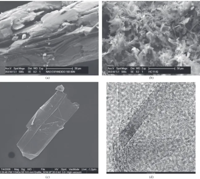
The nano-structures used in this research were supplied by Nacional Grafite Incorporated. The graphene used has its origin from expandable graphite. When the HC 11-IQ graphite is submitted to a 900 °C thermal gradient in a 30 second period or less, the polymeric layers between the graphite plies volatilizes. This sudden reaction leads to the graphite speedy expansion. As the volume must remain constant, the graphite thickness approaches nano scale. The graphite nano sheets are later on functionalized using a mix of sulfuric and nitric acid. Figure 1a shows the expanded graphite before the thermal shock. As it can be noticed, the structure is multilayer, where the polymeric matrix is located between graphite layers. The flake like structure is formed after the thermal expansion as shown
in Figure 1b. From previous results of Ávila’s research group, it is possible to demonstrate that a large amount of graphene was presented into the nano graphite13. Figure 1c shows a scanning electronic microscope (SEM) observation of a single nano graphite sheet. By using a transmission electronic microscope (TEM), they were able to observe clusters of graphene nano sheets piled up as described in Figure 1d.
The single-lap shear adhesion tests were performed at 13 mm/min. For each set of specimens, the mean maximum load, shear stress and displacement at maximum load were defined by applying this constant displacement rate. The failure modes are then classified according to ASTM
D5573[14]. Apparent shear strength of single-lap joints adhesively bonded by tension loadings was chosen for adhesives characterization because it will be easy to extend our results to real life applications, e.g. oil pipes connections and repairs.
Nanoindentation and X-Ray diffraction – XRD are further employed to characterize the performance mechanism of graphite nanoparticles in the epoxy matrix. The nanoindentation procedure is carried out by Asylum Research’s Atomic Force Microscope – AFM model MFP-3D, with a diamond Berkovich tip, at Microscopy Center of Universidade Federal de Minas Gerais – UFMG. The XRD analysis is provided by X-Ray Laboratory of Mining Engineering Department at UFMG. The Philips equipment is Analytical X-ray Diffraction PW3710 and uses a copper anode as source of radiation with wavelength (λ) equals to 1.54439 Å.
3. Results and Discussion
Figure 2 shows a typical force-displacement curve for the three single-lap bonded joints groups studied.
Table 1 summarizes the loads and stresses obtained. As it can be noticed there is a steady increase on peak load with addition of graphene. The addition of 1 wt. (%) of graphene leads to an increase on peak load of approximately 21%. The increase of graphene content from 1 wt. (%) to 2 wt. (%) seems to lead to a nonlinear increase on peak load. The peak force for the 2 wt. (%) samples is 57% higher than the control samples. The graphene addition lead to a greater axial
Table 1. Results for lap-shear adhesion tests.
Sample Id (%)
Load [kN] Stress [MPa] Displacement ± StdDev
[mm]
Max Mean ± StdDev Max Mean ± StdDev
0 9.347 6.631 ± 1.659 14.488 10.228 ± 2.587 2.69 ± 0.39
1 9.592 8.138 ± 0.885 14.723 12.645 ± 1.268 2.85 ± 0.26
2 11.371 10.455 ± 0.653 17.362 15.995 ± 1.009 3.53 ± 0.24
Figure 2. Typical force-displacement curves for single-lap joints tested.
Figure 4. XRD signatures for 1 wt. (%) and 2 wt. (%) specimens.
Figure 5. Reduction in nanostructures mean size.
Figure 6. Nanoindentation curves for adhesive AR300 with 2 wt. (%) graphene addition.
Table 2. Results from nanoindentation tests.
Sample Id (%) Hardness [MPa] E [MPa]
0 396 ± 10.81 3.27 ± 1.41
1 386 ± 8.98 3.82 ± 0.01
2 400 ± 11.32 4.00 ± 0.20
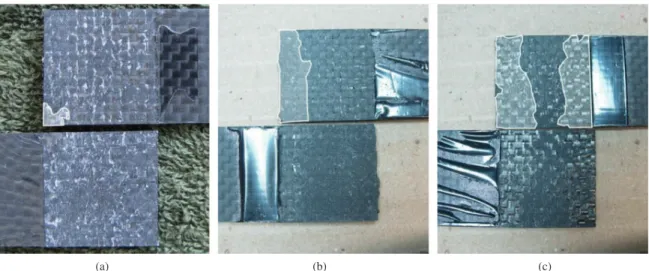
displacement, which may indicate a redistribution of the stresses around the bonded area. In all cases the failure mode seems to keep the same cohesive type. The areas delimited by the white lines into Figure 3 indicate the initial area of failure before the catastrophic one. As it can be observed, the addition of graphene allows having a much higher area of initial failure without catastrophic failure, which can corroborates the hypothesis of stress re-distribution.
The explanation for these changes must remain into the nano-structures formed inside the adhesive and at interface adhesive/adherent. Therefore, a set of X-ray diffraction tests were performed. The XRD signature for the samples is shown in Figure 4.
By applying Bragg’s Law, it is possible to observe no changes on basal spacing. However, the mean size of nanostructures indicates an interesting result. The nanostructure mean size for the 1 wt. (%) samples is approximately of 17.5 mm while for the 2 wt. (%) samples this value is around 16.7 mm. They can be calculated by Scherrer’s equation (Equation 1) as follows15:
cos K D
B ⋅ λ =
⋅ θ (1)
Where D is the average size of the particles, K is a constant (defined as 0,89), B is the width of the characteristic peak curve, λ is the wavelength of the emitted radiation and θ is Bragg’s angle.
The nanostructures seem to be dispersed/exfoliated into small groups of graphene nanosheets (see Figure 5). This smaller size associated to the larger concentration could lead to a much larger number of nanostructures which can act as anchors linking the adhesive to the adherent.
Finally, to be able to check the graphene dispersion, a series of nanoindentation test where performed. Figure 6 shows typical nanoindentation loading-unloading curves for one set of adhesive studied. According to Oliver and Pharr16 the elasticity modulus can be calculated by the unload curve slope of nanoindentation test.
A data summary of hardness and stiffness results is represented into Table 2. No significant increase on hardness is observed, which can lead to the conclusion that failure mechanism on such cases is no influenced by hardness. The stiffness increased 22.3% with 2 wt. (%) addition of graphene nanoparticles.
4. Conclusions
Acknowledgements
The authors would like to acknowledge the financial support provided by the Brazilian Research Council (CNPq) under grants number 303447/2011-7, 472583/2011-5, the Minas Gerais State Research Foundation (FAPEMIG) grant TEC-PPM00192-12, and the Air Force Office of Scientific
Research (AFOSR) under contract FA9550-10-1-0050. We would like to express our gratitude to the Nacional Grafite for providing the HC 11-IQ nano graphite and the Center for Electronic Microscopy Analysis of Universidade Federal de Minas Gerais. And finally, we would also like to express our gratitude to REA Indústria e Comércio Ltda for manufacturing the devices used in this study.
References
1. Tong L and Steven GP. Analysis and Design of Structural Bonded Joints. Boston: Kluwer Academic; 1999. http://dx.doi. org/10.1007/978-1-4615-5133-1
2. Benatar A, Gillespie JJ and Kedward K. Joining of Composites. In: Advanced Composites Manufacturing. New York; 1997. p. 487-512.
3. Jones RM. Mechanics of Composite Materials. 2nd ed. Philadelphia: Taylor & Francis; 1999. p. 540. 325 Chastnut Street, PA 19106.
4. Tsai MY and Morton J. An Evaluation of Analytical and Numerical Solutions to the Single-Lap Joint. International Journal of Solids and Structures. 1994; 31(12):2563-2567. 5. Banea MD and Da Silva LFM. Adhesively bonded joints
in composite materials: an overview. Proceedings of the Institution of Mechanical Engineers, Part L: Journal of Materials Design and Applications. 2009; 223(1):1-18. http:// dx.doi.org/10.1243/14644207JMDA219
6. Zeng Q and Sun CT. A study on composite adhesive lap joint. [PhD Thesis]. West Lafayette: Purdue University; 2001. 7. Ávila AF and Bueno PDO. Stress analysis on a wavy-lap
bonded joint for composites. International Journal of Adhesion and Adhesives. 2004; 24(5):407-414. http://dx.doi. org/10.1016/j.ijadhadh.2003.12.001
8. Turaga UVRS and Sun CT. Improved Design for Metallic and Composite Single-Lap Joints. Journal o f A i rc r a f t. 2008; 45(2):440-447. http://dx.doi. org/10.2514/1.28934
9. Kumar B, Sun CT, Wang PH and Sterkenburg R. Adding Additional Load Paths in a Bonded/Bolted Hybrid Joint. Journal of Aircraft. 2010; 47(5):1593-1598. http://dx.doi. org/10.2514/1.C000206
10. Thostenson ET, Li C and Chou TW. Nanocomposites in context. Composites Science and Technology. 2005; 65(3-4):491-516. 11. Silva Neto A, Ávila AF and Meireles MM. Graphene-based
Nano Reinforcement of Adhesives: The Single Lap Joint Study. In: Proceedings of 21st Brazilian Congress of Mechanical Engineering; 2011; Natal. Natal; 2011.
12. American Society for Testing and Materials - ASTM. D5868-01: Test Method for Lap Shear Adhesion for Fiber Reinforced Plastic (FRP) Bonding. ASTM International; 2008.
13. Ávila AF, Yoshida MI, Carvalho MGR, Dias ÉC and Ávila Junior Jd. An investigation on post-fire behavior of hybrid nanocomposites under bending loads. Composites Part B: Engineering. 2010; 41(5):380-387. http://dx.doi.org/10.1016/j. compositesb.2010.02.002
14. American Society for Testing and Materials - ASTM. D5573-99: Practice for Classifying Failure Modes in Fiber-Reinforced-Plastic (FRP) Joints. ASTM International; 2005.
15. Birks LS and Friedman H. Particle Size Determination from X-Ray Line Broadening. Journal of Applied Physics. 1946; 17(8):687-692. http://dx.doi.org/10.1063/1.1707771